SECTION 5-F – 1959 BUICK TRIPLE TURBINE TRANSMISSION REMOVAL AND INSTALLATION DISASSEMBLY AND ASSEMBLY
5-36 REMOVAL AND INSTALLATION OF TRIPLE TURBINE TRANSMISSION
1959 Buick Triple Turbine Transmission Removal
- Hoist front and rear of car and rest it solidly on stands placed under frame. Frame side rail should be at least 20″ above floor.
- Disconnect track bar and shock absorbers at axle housing.
- Disconnect parking brake cable at equalizer and brake pipe at torque tube bracket.
- Remove exhaust pipe(s).
- Disconnect torque tube from torque ball and move rear axle back to disengage propeller shaft from universal joint.
- Remove converter housing cover.
- Turn flywheel until one converter drain plug can be loosened sufficiently to provide an air vent, then turn flywheel until opposite drain plug is straight down. Remove this plug and allow oil to drain from converter.
- Remove filler pipe from oil pan to drain oil from transmission.
- Remove bolts to disconnect converter from flywheel.
- Disconnect speedometer cable, disconnect shift rod from shift lever, and disconnect stator operating control rod.
- Carefully mark transmission support and frame at each end of support so support may be reinstalled in same fore and aft position. This step is necessary to insure against any shear strain being imposed on the engine mountings when support is reinstalled.
- Place transmission jack or hoist in position and adjust it to securely support the transmission in accordance with instructions for the equipment being used.
- Remove two nuts and four bolts and nuts holding mount to support.
- Raise transmission just enough to take weight off support. Remove eight support to frame member bolts. If shims are present, carefully note number and location so they may be reinstalled in original location.
- Place suitable jack under rear end of engine lower crankcase so that engine will be safely supported while transmission is removed. CAUTION: Do not use bar with hooks placed over frame side rails because brake pipes on top of left side rail will be damaged.
- Lower transmission slightly and disconnect cooler pipes.
- Lower the transmission just enough so that converter housing bolts can be reached. With engine and transmission supported by the separate jacks, disconnect the converter housing from engine crankcase.
- Move transmission rearward to disengage hub of converter pump cover from crankshaft, lower transmission and remove it from under car.
Installation of Transmission
- Turn flywheel so that one hole for converter attaching bolt is straight up and notched flange is down.
- Raise transmission into place with same equipment as used for removal. Align converter attaching bolt holes with holes in flywheel before moving transmission forward against cylinder crankcase.
- Adjust lifting equipment so that converter housing meets the engine crankcase squarely and engages the two dowels. Then install all converter housing bolts with lock washers. Tighten all bolts uniformly to 45-55 ft. lbs. torque.
- Attach oil cooler pipes.
- Reassemble mounts and support to transmission. Reinstall shims between support and frame in their original position. Take care to locate support fore and aft in its original position to avoid putting any shear strain on the engine mounts. Install support to frame bolts. Refer to Par. 2-25 for mount adjustment.
- Attach flywheel to converter using 5/16″-24 300M bolts. Bolts of lesser quality must not be used at this location. 300M bolts can be identified by six radial marks on the bolt head.
- Remove transmission hoist and engine support or jack.
- Check converter drain plugs for tightness, then install converter housing cover.
- Attach oil filler pipe to oil pan.
- Align blind spline on propeller shaft with blank spline in universal joint, move axle assembly forward to engage splines. Connect torque tube to torque ball with bolts and lock washers.
- Reassemble exhaust system making sure that pipes are centered in the frame member holes and that the system is free from binds.
- Reconnect track bar and shock absorbers to axle brackets.
- Reconnect parking brake cable at equalizer and brake pipe at torque tube bracket. Bleed rear brakes.
- Connect speedometer cable to driven gear sleeve and connect shift rod to shift lever on transmission. Connect stator operating control rod to lever.
- Wipe all oil from outside of transmission then lower car to floor.
- Tighten torque ball bolts (see par. 4-12) .
- Fill transmission to proper level as described in paragraph 1-4.
- Check adjustment of control linkage. Check adjustment of stator operating controls and throttle linkage (par. 3-9).
- Road test car for approximately 20 miles with frequent stops and starts as might be encountered in heavy traffic. A thorough road warm-up is desired.
- Place car on hoist and carefully examine the transmission and all connections for oil leaks. Recheck oil level.
5-37 TRIPLE TURBINE CONVERTER: REMOVAL, DISASSEMBLY, INSPECTION, REASSEMBLY
Converter Pump Cover Removal and Inspection
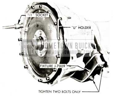
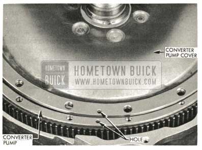
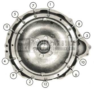
- Assemble Triple Turbine transmission to fixture J-7009 taking care to tighten the two bolts on one side of the fixture only. Install the two bolts on the opposite side finger tight. Remove the twelve converter bolts using a “U” holder and 1/2″ socket.
NOTE: Converter pump cover bolt s are 300M steel identified by six radial marks on the bolt head.
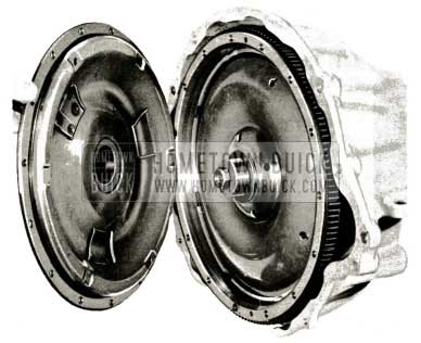
1959 Buick Assemble Triple Turbine Transmission
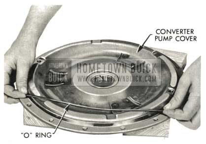
- Pry to loosen, remove cover and “O” ring. Discard “O” ring.
1959 Buick Triple Turbine Transmission – Remove Cover and O-Ring
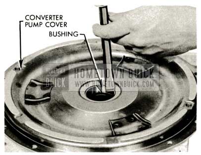
1959 Buick Triple Turbine Transmission – Converter Pump Bushing
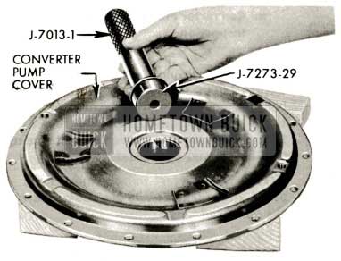
1959 Buick Triple Turbine Transmission – Converter Cover Bushing
Turbine Removal
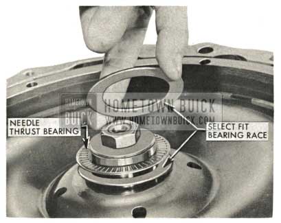
- Remove select fit bearing races and needle thrust bearing. (Between first turbine hub and converter pump cover.) Place in converter pump cover.
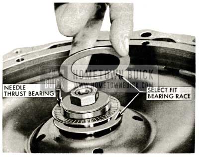
1959 Buick Triple Turbine Transmission – Select Fit Bearing Race
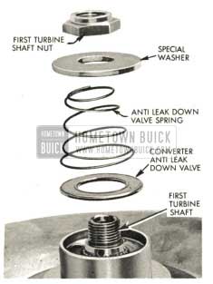
- Remove first turbine shaft nut, special washer, converter anti-leak down valve spring, and anti-leak down valve.
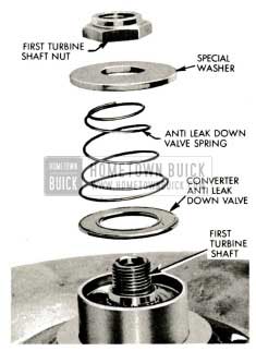
1959 Buick Triple Turbine Transmission – First Turbine Shaft Nut
1959 Buick Triple Turbine Transmission – First Turbine Disc
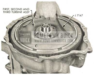
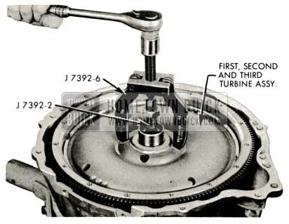
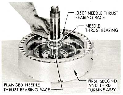
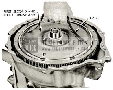
1959 Buick Triple Turbine Transmission – First, Second and Third Turbine Assembly
Turbine Disassembly and Inspection
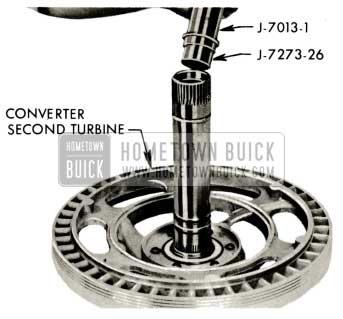
- Remove needle bearing, flanged needle from second turbine hub.
NOTE: These races and bearing may have remained on top of stator.
1959 Buick Triple Turbine Transmission – Install Flanged Needle Bearing Race
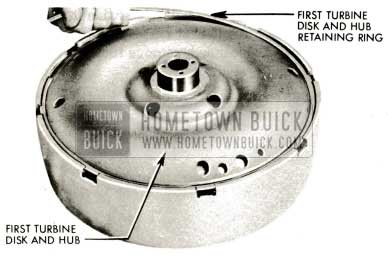
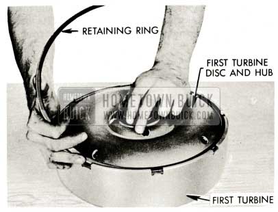
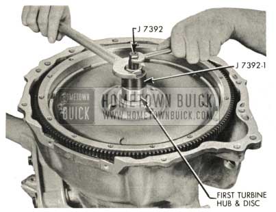
- Set assembly shafts down through hole in bench. Remove first turbine to disc and hub retainer ring. Use a thin bladed screwdriver at inner edge of ring to raise edge of ring. Press on outer edge of ring to slide ring up slope of thin screwdriver over step of first turbine disc and hub.
1959 Buick Triple Turbine Transmission – Assembly Shafts
1959 Buick Triple Turbine Transmission – First Turbine Disc and Hub
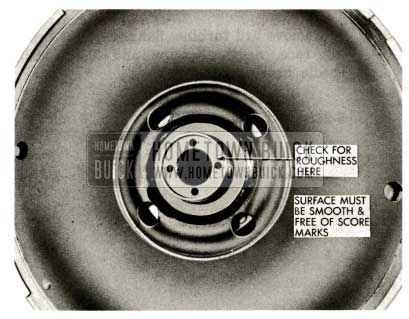
1959 Buick Triple Turbine Transmission – Check Turbine Disc and Hub
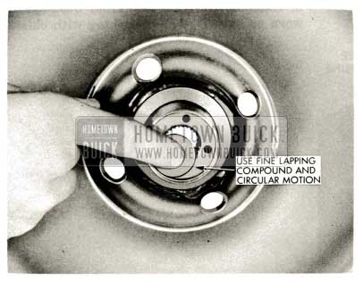
1959 Buick Triple Turbine Transmission – Anti-Leakdown Valve Seat
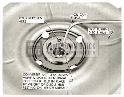
1959 Buick Triple Turbine Transmission – Anti-Leakdown Valve and Spring
Pour kerosene in any of the four holes until the level is nearly to the top. The valve should hold the kerosene for several minutes. If the kerosene leaks down, the valve may have a nick or scratch or the valve seat may require more lapping.
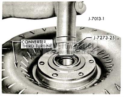
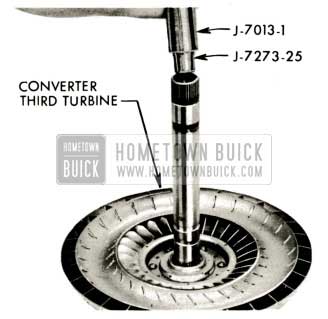
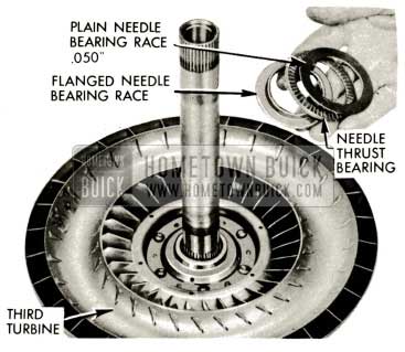
- Remove 3rd turbine, flanged needle bearing race, needle bearing and .050″ plain needle bearing race.
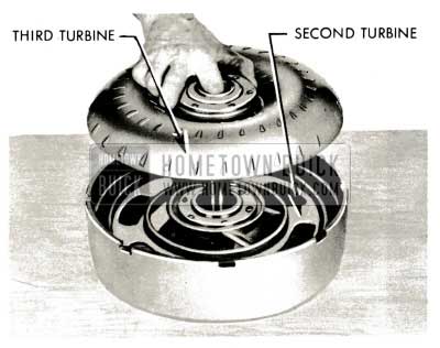
1959 Buick Triple Turbine Transmission – Remove Third Turbine
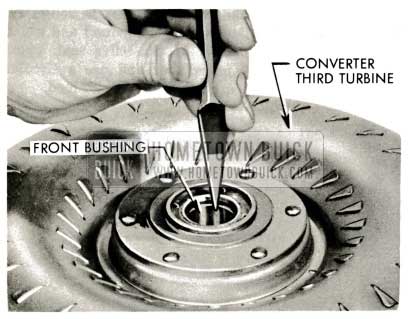
1959 Buick Triple Turbine Transmission – Examine Third Turbine Front Bushing
1959 Buick Triple Turbine Transmission – Third Turbine Front Bushing
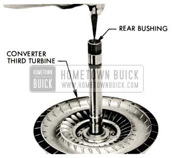
1959 Buick Triple Turbine Transmission – Third Turbine Rear Bushing
1959 Buick Triple Turbine Transmission – Install Third Turbine Rear Bushing
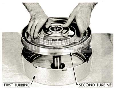
1959 Buick Triple Turbine Transmission – Remove Second Turbine
1959 Buick Triple Turbine Transmission – Second Turbine Shaft
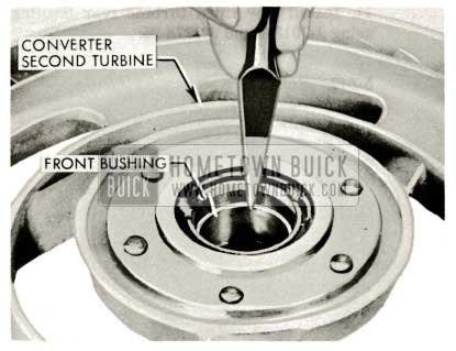
1959 Buick Triple Turbine Transmission – Second Turbine Shaft Front Bushing
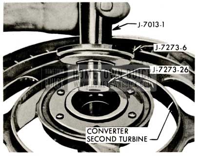
1959 Buick Triple Turbine Transmission – Install Second Turbine Shaft Front Bushing
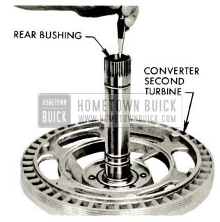
1959 Buick Triple Turbine Transmission – Examine Second Turbine Shaft Rear Bushing
1959 Buick Triple Turbine Transmission – Install Second Turbine Shaft Rear Bushing
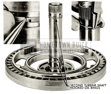
NOTE: Second turbine shaft oil rings are slightly smaller (.050″) than two rings used on the output shaft. These rings must not be interchanged with those used on the output shaft.
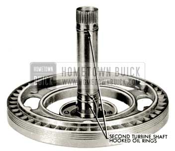
1959 Buick Triple Turbine Transmission – Hooked Oil Rings
Reassembly of Turbines
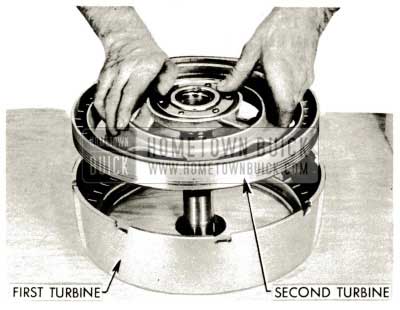
- Lubricate second turbine shaft front and rear bushings and insert 2nd turbine with oil rings in place through hole in bench to rest on 1st turbine.
1959 Buick Triple Turbine Transmission – Lubricare Second Turbine
NOTE: Always measure needle bearings and races. Some are within .010″ thickness and 1/16″ diameter of each other and can easily be incorrectly assembled.
1959 Buick Triple Turbine Transmission – Flanged Needle Bearing Race
- With needle bearing and races held in place with heavy lube, insert 3rd turbine shaft into 2nd turbine shaft. Lower into position.
NOTE: Heavy lube referred to in this manual can be wheel bearing grease or chassis lube. Use only enough to hold bearings and races in place.
1959 Buick Triple Turbine Transmission – Remove Third Turbine
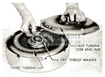
- Inspect and, if necessary to replace, place new .080″ lead-coated bronze thrust washer on hub of 3rd turbine. Lubricate washer and position 1st turbine disc and hub with tangs in slots of 1st turbine.
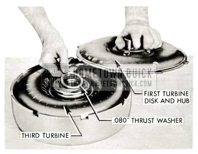
1959 Buick Triple Turbine Transmission – Thrust Washer
1959 Buick Triple Turbine Transmission – Install First Turbine Disc
1959 Buick Triple Turbine Transmission – Install Flanged Needle Bearing Race
Removal, Disassembly and Inspection of Infinitely Variable Pitch Stator
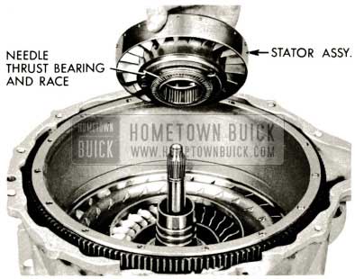
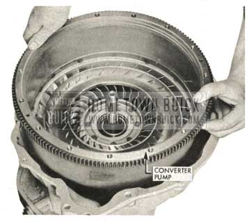
- Lift converter pump until stator race is clear of splines on reaction shaft (approximately 2 1/2″). Lower converter pump and remove the stator. To avoid pinching fingers, use caution when lowering pump.
Remove needle thrust bearing and bearing race (Stator cam to converter pump hub).
1959 Buick Triple Turbine Transmission – Converter Pump
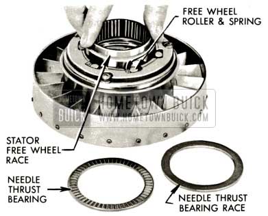
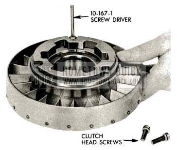
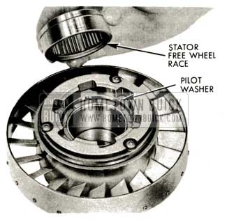
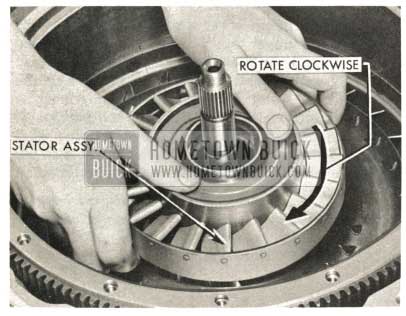
- Pull out stator free wheel race while rotating clockwise. Examine the race. Its outer surface should be free of nicks or dents.
1959 Buick Triple Turbine Transmission – Stator Free Wheel Race
1959 Buick Triple Turbine Transmission – Stator Free Wheel Cam Assembly
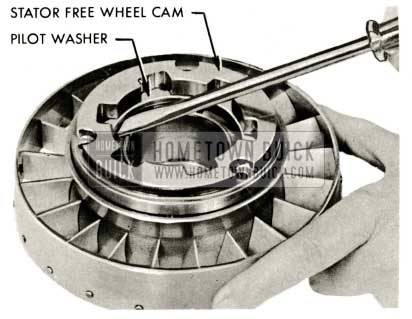
1959 Buick Triple Turbine Transmission – Stator Free Wheel Cam
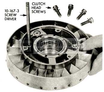
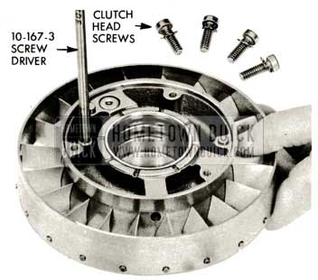
1959 Buick Triple Turbine Transmission – Clutch Head Screws and Lock Washers
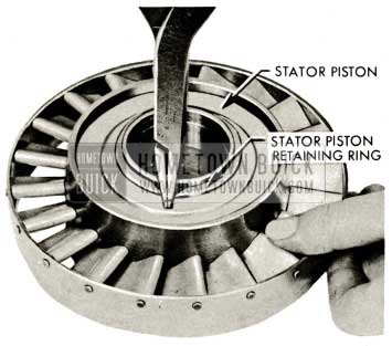
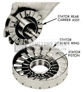
1959 Buick Triple Turbine Transmission – Stator Piston Retaining Ring
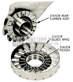
1959 Buick Triple Turbine Transmission – Stator Blades Assembly
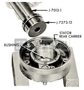
1959 Buick Triple Turbine Transmission – Stator Rear Carrier Bushing
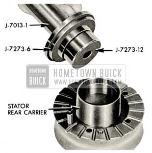
1959 Buick Triple Turbine Transmission – Install Stator Rear Carrier Bushing
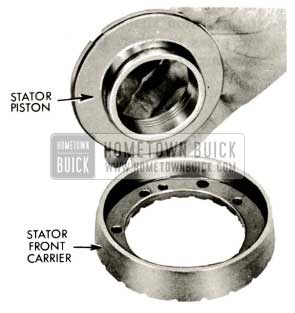
1959 Buick Triple Turbine Transmission – Stator Piston
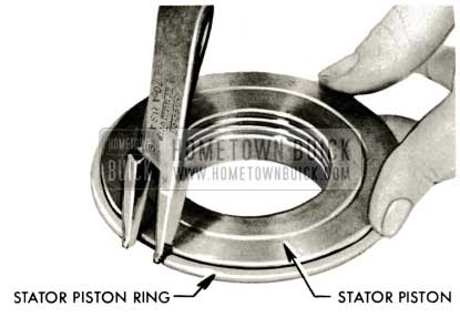
1959 Buick Triple Turbine Transmission – Stator Piston Ring
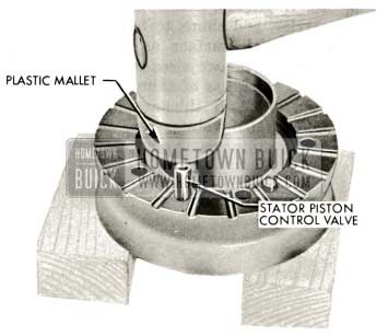
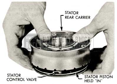
1959 Buick Triple Turbine Transmission – Stator Piston Control Valve
1959 Buick Triple Turbine Transmission – Stator Piston Shoulder
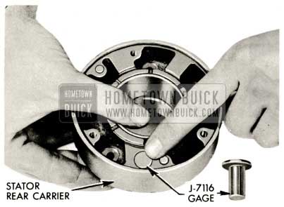
1959 Buick Triple Turbine Transmission – Stator Control Valve Gage J-7116
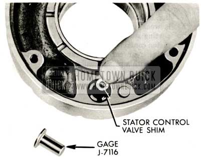
1959 Buick Triple Turbine Transmission – Stator Control Valve Shim
Reassembly of Infinitely Variable Pitch Stator
- After stator valve has been checked and shims added if necessary, assemble valve, new service spring, and retainer to stator rear carrier.
NOTE: Be certain shims lay fiat in position inside valve bore.
Service springs only must be used after shims have been selected with Gauge J-7116. Service springs are held to much closer tolerances than production springs and are calibrated especially for use with Gauge J-7116. Under no circumstances should the original thickness of shims be altered unless Gauge J-7116 is used to determine the shim thickness and the shims so selected are installed with a service spring.
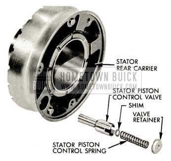
1959 Buick Triple Turbine Transmission – Infinitely Variable Pitch Stator
- Tap new valve retainer into stator carrier squarely and flush with stator carrier surface. Use flat tool to drive retainer to prevent cocking of retainer during installation.
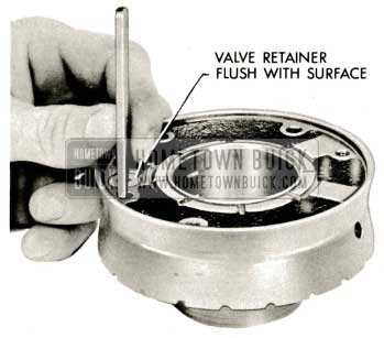
1959 Buick Triple Turbine Transmission – Valve Retailer Flush
NOTE: This gap serves as the piston “bleed” hole for the stator piston.
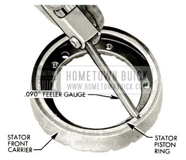
1959 Buick Triple Turbine Transmission – Insert Stator Piston Ring
- Expand and install stator piston ring on stator piston.
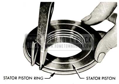
1959 Buick Triple Turbine Transmission – Install Stator Piston Ring
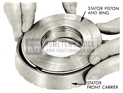
1959 Buick Triple Turbine Transmission – Install Piston
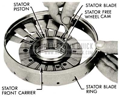
1959 Buick Triple Turbine Transmission – Blades and Cranks
1959 Buick Triple Turbine Transmission – Install Blades
1959 Buick Triple Turbine Transmission – Stator Blades
1959 Buick Triple Turbine Transmission – Clutch Head
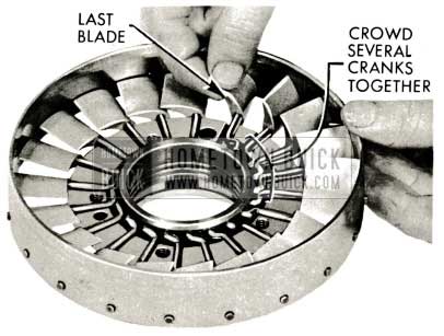
NOTE: Tangs on retaining ring must enter slots in sleeve. Move stator blades from high to low angle several times. Check for free operation.
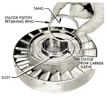
1959 Buick Triple Turbine Transmission – Install Stator Piston Retaining Ring
- Inspect pilot washer and if necessary to replace, suitably support stator free wheel cam and remove pilot washer using a plastic hammer and drift.
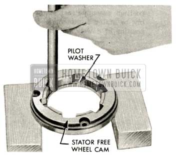
1959 Buick Triple Turbine Transmission – Pilot Washer
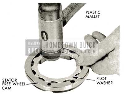
1959 Buick Triple Turbine Transmission – Install Pilot Washer
1959 Buick Triple Turbine Transmission – Stator Free Wheel Cam Assembly
1959 Buick Triple Turbine Transmission – Stator Free Wheel Clutch
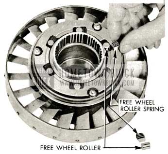
1959 Buick Triple Turbine Transmission – Free Wheel Clutch Rollers
NOTE: Race next to free wheel rollers and springs.
NOTE: If the needle thrust bearing or race is scored or worn, both must be replaced.
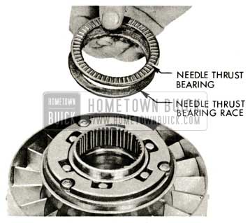
1959 Buick Triple Turbine Transmission – Needle Thrust Bearing
- Set assembly aside if further work is to be done on transmission. Refer to paragraph 5-56 for installation of stator assembly.
1959 Buick Triple Turbine Transmission Assembly
Removal of Converter Pump. Inspection, Removal, and Replacement of Stator Cam to Pump Hub Bearing Race
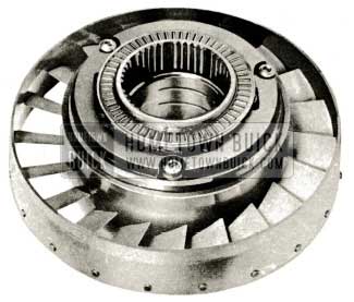
- Remove converter pump by lifting straight up.

1959 Buick Triple Turbine Transmission – Converter Pump
- Examine needle thrust bearing race staked to converter hub. (Stator cam to converter pump hub needle thrust bearing race.) If worn or scored, carefully chip out staking with cape chisel and remove worn race.
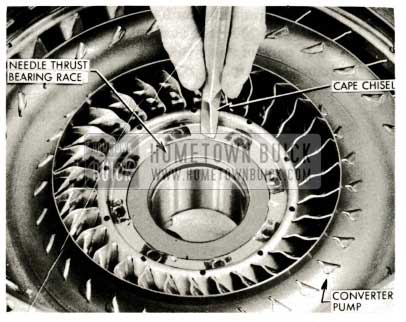
1959 Buick Triple Turbine Transmission – Needle Thrust Bearing Race
Refer to paragraph 5-56 f or installation of converter pump.
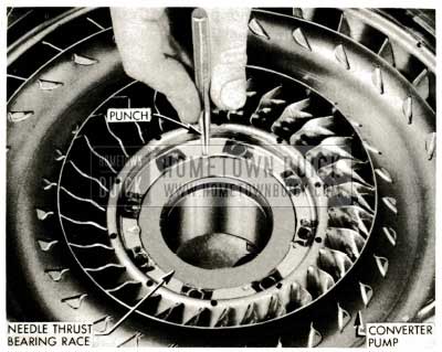
1959 Buick Triple Turbine Transmission – Install Needle Thrust Bearing Race
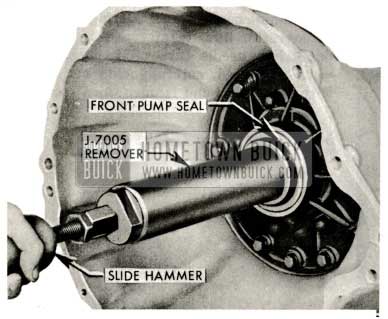
5-38 TRIPLE TURBINE PUMP SEAL REMOVAL AND REPLACEMENT
- With transmission horizontal, thread seal remover J-7005 into seal until threads engage steel part of seal. Install slide hammer and hammer sharply to remove seal.
NOTE: If reaction shaft, pump, and reverse piston assembly is to be removed, pump seal may be removed on bench.
1959 Buick Triple Turbine Transmission Pump Seal
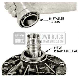
- Install new pump seal with pump in transmission using Tool J-7006.
NOTE: It is not necessary to remove the planet sets, first turbine shaft, and output shaft assembly to remove and reinstall the pump seal or the complete pump-reverse piston assembly.
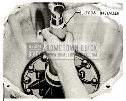
1959 Buick Triple Turbine Transmission Pump Seal Installation
5-39 REACTION SHAFT AND FLANGE, PUMP, REVERSE PISTON ASSEMBLY: REMOVAL, DISASSEMBLY, INSPECTION AND REASSEMBLY
Removal of Stator Reaction Shaft and Flange, Pump and Reverse Piston Assembly
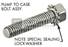
- Remove ten pump body to case bolts (3/16” socket).
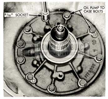
1959 Buick Triple Turbine Transmission Reaction Shaft
Refer to paragraph 5-48 for installation of pump-reaction shaft and flange assembly.
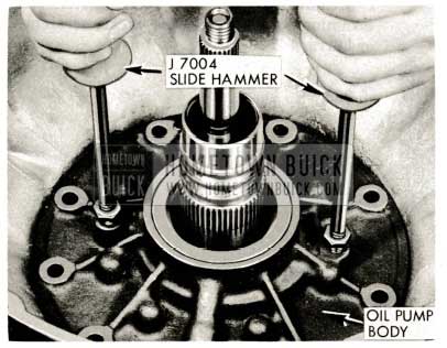
1959 Buick Triple Turbine Transmission – J-7004 Slide Hammer
Disassembly, Inspection and Reassembly of Stator Reaction Shaft and Flange, Pump, and Reverse Piston Assembly
- Remove needle thrust bearing and flanged rear thrust bearing race (between stator reaction shaft and front planet ring gear assembly). Remove reaction flange to case gasket.
NOTE: This bearing and rear race may have stuck to front planet set ring gear carrier during disassembly.
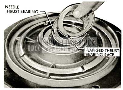
1959 Buick Triple Turbine Transmission – Flanged Thrust Bearing Race
- Remove reverse clutch piston. Use pliers to grip ribs of piston if piston sticks in bore.
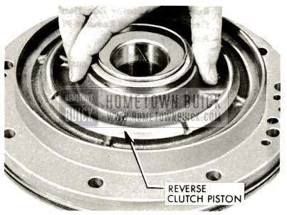
1959 Buick Triple Turbine Transmission – Reverse Clutch Piston
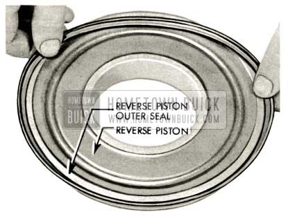
1959 Buick Triple Turbine Transmission – Reverse Piston Outer Seal
On jobs equipped with rubber inner oil seal: Pull off and discard rubber inner oil seal.
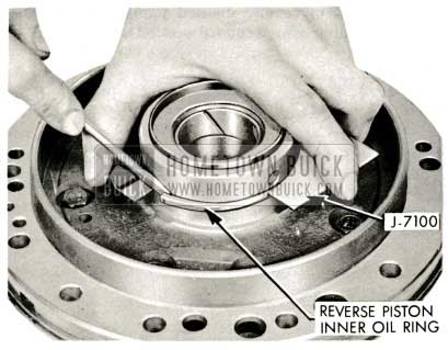
1959 Buick Triple Turbine Transmission – Reverse Piston Inner Oil Ring
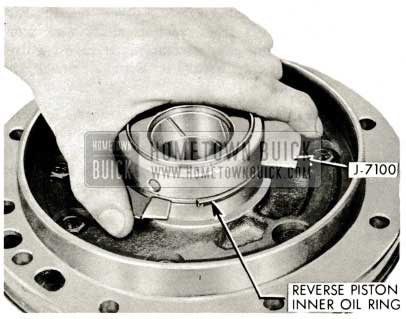
1959 Buick Triple Turbine Transmission – Reverse Piston Inner Oil Ring Installation
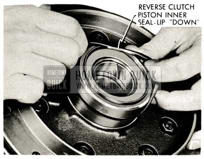
1959 Buick Triple Turbine Transmission – Reverse Clutch Inner Oil Seal-Lip
1959 Buick Triple Turbine Transmission – Pump Body
NOTE: This bearing race is specially hardened and is very brittle. It is not likely it will need replacement; however, if it is to be ‘replaced, be careful to use eye protection as the race may shatter when struck with chisel.
1959 Buick Triple Turbine Transmission – Flanged Needle Thrust Bearing Race Inspection
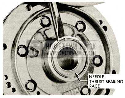
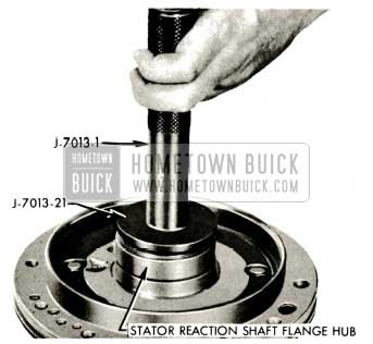
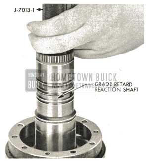
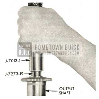
- Inspect reaction shaft rear end; clean up all burrs and nicks.
Install new flanged needle thrust bearing race squarely in reaction shaft using Tool J-7013-1 Handle, and J-7013-21 Installer.
1959 Buick Triple Turbine Transmission – Reaction Shaft Rear End
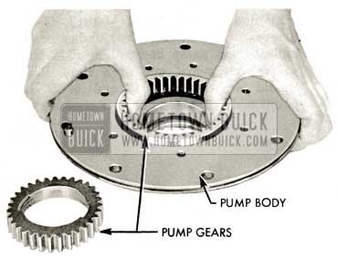
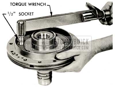
- Remove seven reaction flange to pump body bolts ( 1/2″ socket).
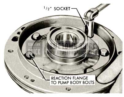
1959 Buick Triple Turbine Transmission – Reaction Flange to Pump Body Bolts
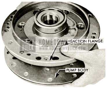
1959 Buick Triple Turbine Transmission – Remove Pump Body
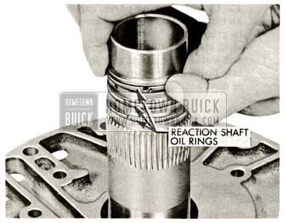
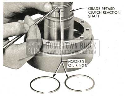
1959 Buick Triple Turbine Transmission – Replace Reaction Shaft Oil Rings
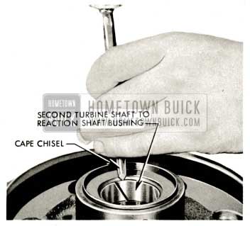
1959 Buick Triple Turbine Transmission – Examine Second Turbine Shaft
1959 Buick Triple Turbine Transmission – Drive out Bushing
Hold one end of hooked ring firmly in groove and work other end of ring into position. Rotate hooked ring in groove to check for burrs or dirt that may be present.
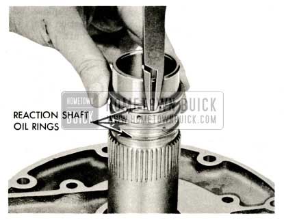
1959 Buick Triple Turbine Transmission – Install Reaction Shaft Oil Rings
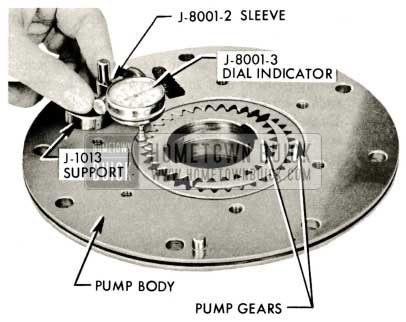
- Check pump gear end clearance using Dial Indicator Support J-1013, J-8001-2 Sleeve, and J-8001-3 Dial Indicator. Zero indicator on pump body, then slide plunger to rest on gears, one at a time. Reading should be between .001″ and .0025″ below pump body. Replace pump if necessary.
1959 Buick Triple Turbine Transmission – Pump Gear
1959 Buick Triple Turbine Transmission – Pump Drive Gear
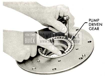
1959 Buick Triple Turbine Transmission – Pump Driven Gear
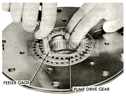
NOTE: All surfaces of these gears are accurately ground and must be protected against nicks, scratches and dirt of any kind. Examine pump bushing. If bushing is badly scored or worn, pump assembly must be replaced.
1959 Buick Triple Turbine Transmission – Remove Pump Gear
- If pump seal is to be replaced at this time rather than with pump in transmission, suitably support pump body and drive out pump seal using drift and hammer.
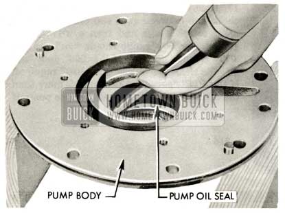
1959 Buick Triple Turbine Transmission – Pump Seal
NOTE: Pump drive gear must be installed with notched driving flange “up” and counter-bored side toward pump seal.
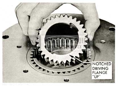
1959 Buick Triple Turbine Transmission – Pump Gear Lubrication
- Lubricate and carefully assemble pump assembly to reaction shaft flange assembly. Note position of dowel pins in pump body and holes in reaction shaft flange. The surfaces of these two parts must be clean before assembly.
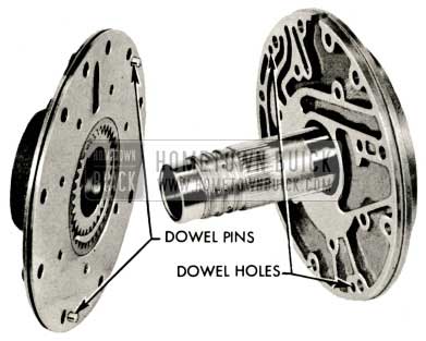
1959 Buick Triple Turbine Transmission – Pump Assembly
1959 Buick Triple Turbine Transmission – Install Shaft Flange to Pump Body Bolts
NOTE: Reaction shaft pilots tool to insure square seating of seal.
1959 Buick Triple Turbine Transmission – Pump Oil Seal
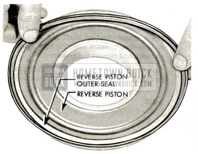
- Install new reverse piston outer seal with lip away from ribbed side of piston.
1959 Buick Triple Turbine Transmission – Reverse Piston Seal
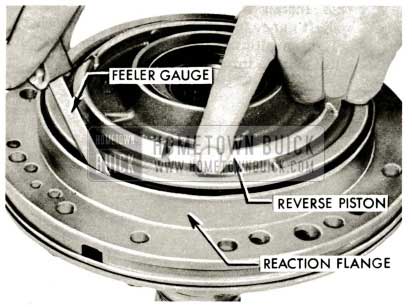
1959 Buick Triple Turbine Transmission – Reverse Piston Seals
If further work is to be done on transmission, set assembly aside.
Refer to paragraph 5-48 for installation of reaction shaft-pump assembly.
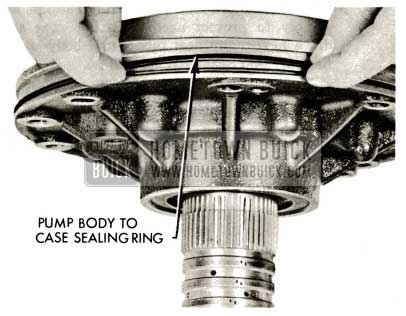
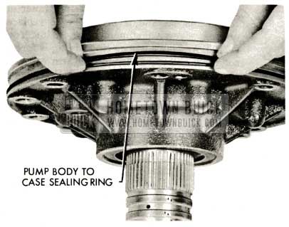
1959 Buick Triple Turbine Transmission – Pump Body to Case Sealing Ring
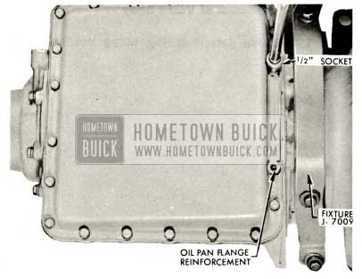
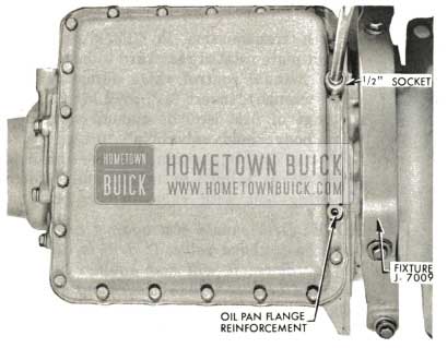
5-40 OIL PAN AND SCREEN REMOVAL
- With transmission upside down, remove twenty oil pan bolts (1/2″ socket), oil pan flange reinforcement and oil pan. Remove and discard oil pan gasket.
1959 Buick Triple Turbine Transmission – Oil Pan
Refer to paragraph 5-54 for installation of oil pan and oil screen.
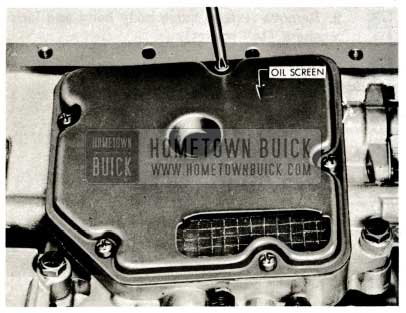
1959 Buick Triple Turbine Transmission – Remove Oil Screen
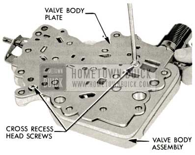
5-41 VALVE BODY: REMOVAL, DISASSEMBLY, INSPECTION AND REASSEMBLY
Removal of Valve Body
- Remove detent spring using needle nose pliers.
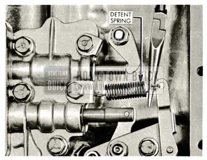
1959 Buick Triple Turbine Transmission – Valve Body Detent Spring
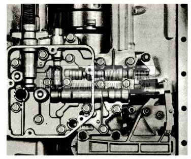
1959 Buick Triple Turbine Transmission – Valve Body Bolts
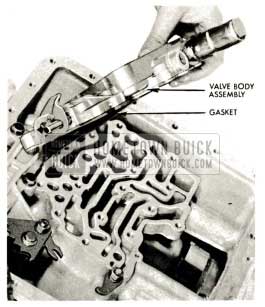
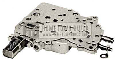
1959 Buick Triple Turbine Transmission – Valve Body Assembly
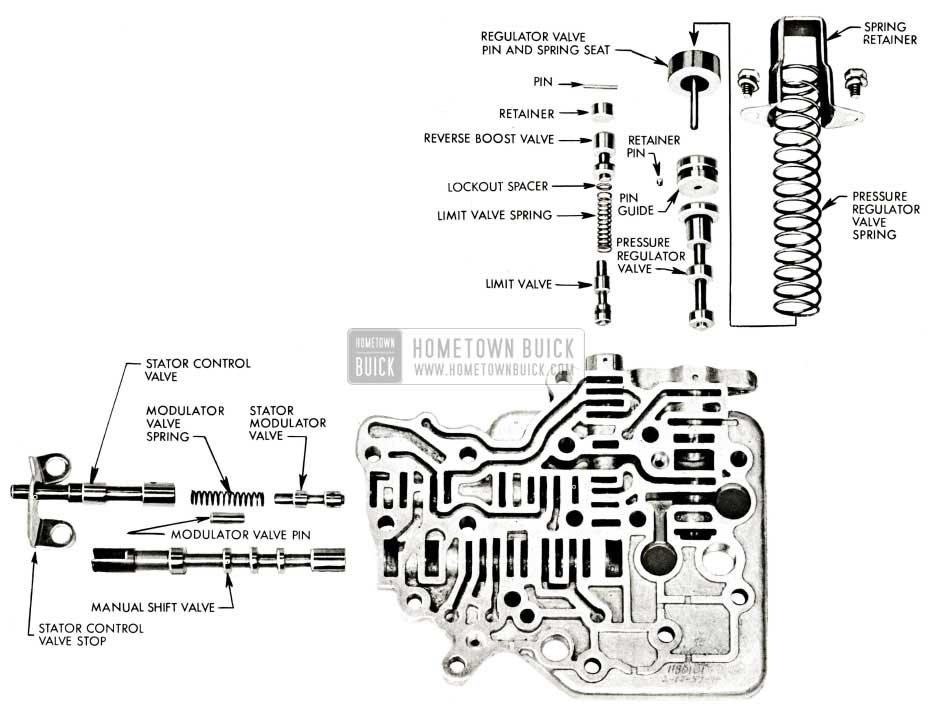
Disassembly and Inspection of Valve Body
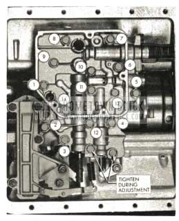
Use the exploded view of the valve body as a guide during disassembly.
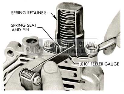
- Remove pressure regulator valve spring retainer and spring seat and pin using Tool J-7007 and 7/16″ wrench.
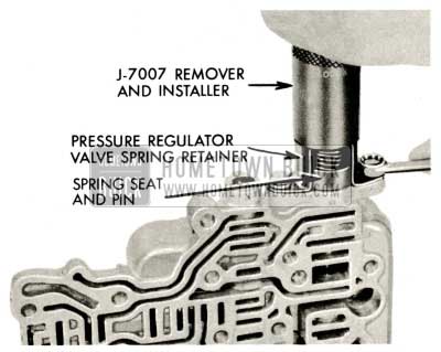
1959 Buick Triple Turbine Transmission – Remove Pressure Regulator
1959 Buick View of Valve Body Disassembled
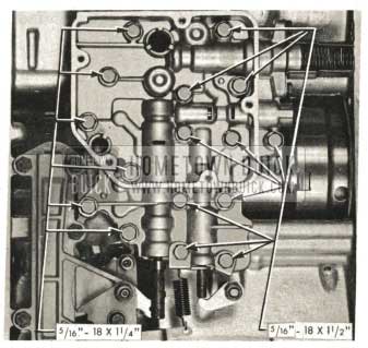
Assembly of Valve Body
Use the exploded view of the valve body as a guide during assembly (Figure 5-333).
- Install limit valve, grooved land first. Shake valve body to allow limit valve to reach proper position.
NOTE: Limit valve and stator modulator valve are identical and interchangeable.
- Install limit valve spring (longer than stator modulator valve spring) and reverse boost valve lockout spacer.
- Install reverse boost valve, narrow land first.
- Insert reverse boost valve retainer. Depress retainer against spring pressure and install retainer pin flush with surface of valve body.
- Insert pressure regulator valve, small end first.
- Insert pressure regulator valve pin guide so end is just flush with edge of valve body.
- Install pressure regulator valve pin guide retainer pin into valve body and groove of pin guide.
- Insert stator modulator valve into valve body, grooved land first. Shake valve body to allow modulator valve to reach proper position.
- Install stator modulator valve spring.
- Install stator modulator valve pin inside modulator valve spring.
- Install stator control valve.
- Install shift control valve, slotted end out.
- Insert pressure regulator valve pin and spring seat into pin guide.
- Install pressure regulator valve spring and spring retainer using Tool J-7007.
1959 Buick Triple Turbine Transmission – Remove Pressure Regulator
1959 Buick Triple Turbine Transmission – Spring Seat
1959 Buick Triple Turbine Transmission – Valve Body Plate
Refer to paragraph 5-52 for installation of valve body.
1959 Buick Triple Turbine Transmission – Sub-Assembly Side
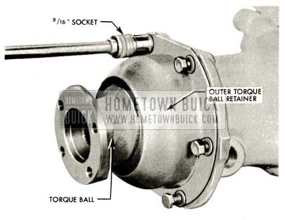
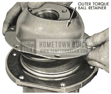
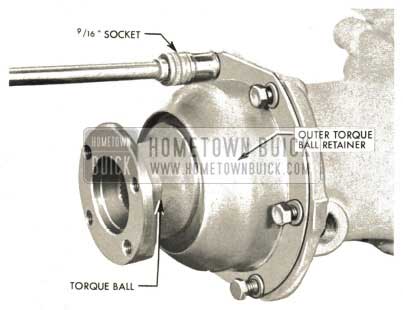
5-42 TORQUE BALL, TORQUE BALL RETAINERS AND UNIVERSAL JOINT REMOVAL AND INSPECTION
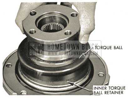
- Remove six torque ball retainer bolts (9/16 ” socket). Remove outer torque ball retainer. Remove torque ball.
Examine rubber bonded to torque ball for tears or other failure that might cause leaks. Examine outer torque ball retainer for roughness or dents that could damage torque ball; discard if defective.
1959 Buick Triple Turbine Transmission – Torque Ball
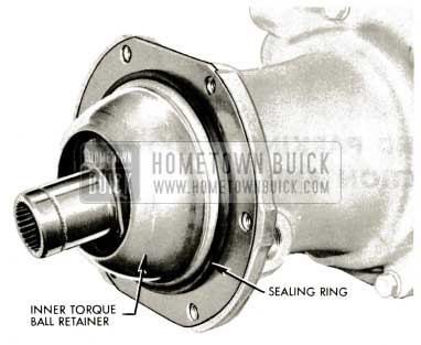
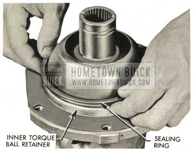
- Remove sealing ring from outside of inner torque ball retainer.
Examine sealing ring for cracks or defects that might cause leaks; discard if defective. Examine surface of inner torque ball retainer for score marks or roughness that could damage torque ball; discard if defective.
1959 Buick Triple Turbine Transmission – Inner Torque Ball Retainer
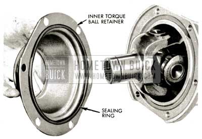
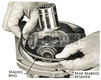
- Remove inner torque ball retainer. Remove sealing ring, inner torque ball retainer to rear bearing retainer. Examine sealing ring; discard if defective.
1959 Buick Triple Turbine Transmission – Sealing Ring
1959 Buick Triple Turbine Transmission – Universal Joint
5-43 MANUAL CONTROL AND PARKING LOCK: REMOVAL, DISASSEMBLY, INSPECTION AND REASSEMBLY
Removal of Manual Control Shaft Lever Seal and Bearing
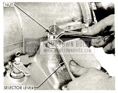
- Remove transmission selector lever shaft nut (5/8″ wrench). Hold lever with hand while loosening nut to avoid damaging strain on internal parts.
1959 Buick Triple Turbine Transmission – Selector Lever Shaft Nut
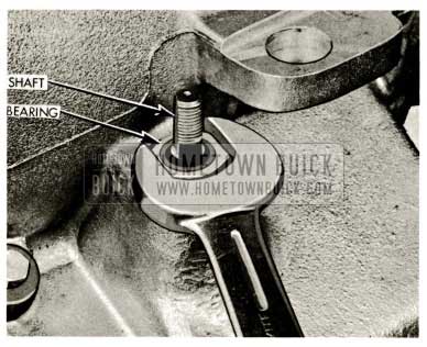
1959 Buick Triple Turbine Transmission – Selector Lever Shaft Bearing
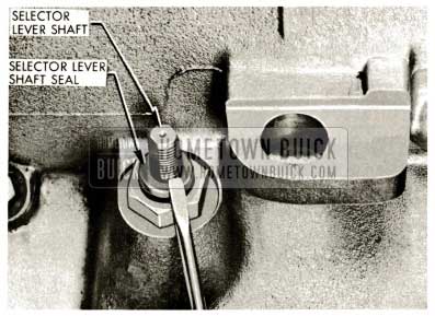
1959 Buick Triple Turbine Transmission – Check Shaft Seal
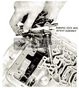
Removal of Manual Control and Parking Lock
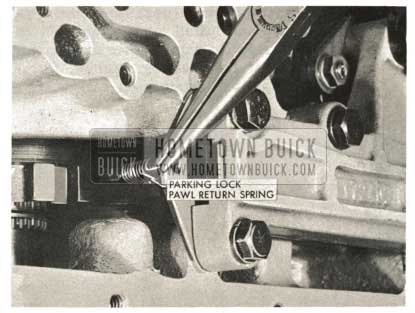
- Remove parking lock pawl return spring using needle nose pliers.
1959 Buick Triple Turbine Transmission – Install Parking Lock Pawl
1959 Buick Triple Turbine Transmission – Parking Lock
1959 Buick Triple Turbine Transmission – Remove Parking Lock
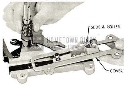
Disassembly, Inspection and Reassembly of Manual Control and Parking Lock
- Remove slide and roller with slide and roller cover. Check for damaged or excessively worn rollers.
1959 Buick Triple Turbine Transmission – Slide and Roller
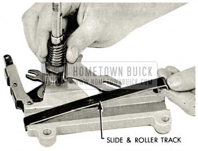
1959 Buick Triple Turbine Transmission – Remove Slide and Roller Track
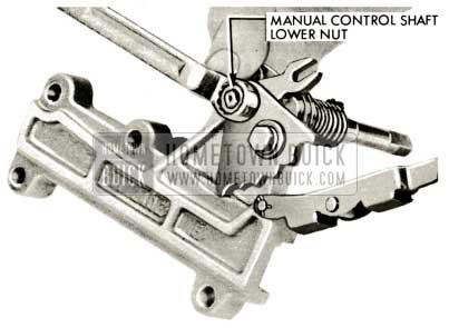
1959 Buick Triple Turbine Transmission – Remove Manual Control Shaft
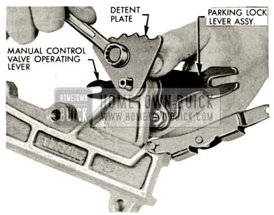
1959 Buick Triple Turbine Transmission – Manual Control Valve Operating Lever
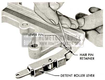
1959 Buick Triple Turbine Transmission – Hair Pin Retainer
1959 Buick Triple Turbine Transmission – Clamp Lower Flats
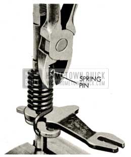
1959 Buick Triple Turbine Transmission – Spring Pin
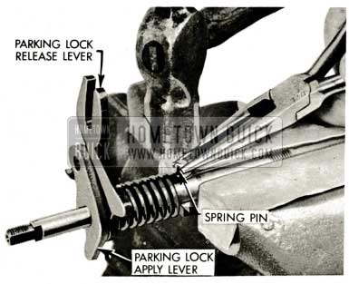
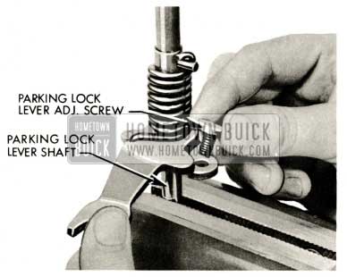
1959 Buick Triple Turbine Transmission – Parking Lock Release Lever
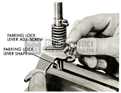
1959 Buick Triple Turbine Transmission – Parking Lock Lever Adjusting Screw
1959 Buick Triple Turbine Transmission – Hair Pin Retainer
1959 Buick Triple Turbine Transmission – Manual Control Valve Operating Lever
1959 Buick Triple Turbine Transmission – Remove Manual Control Shaft
1959 Buick Triple Turbine Transmission – Remove Slide and Roller Track
Refer to paragraph 5-50 for installation of manual control and parking lock assembly.
1959 Buick Triple Turbine Transmission – Slide and Roller
5-44 PARKING LOCK PAWL SHAFT AND PAWL REMOVAL
- If the parking lock pawl or the pawl shaft require replacement, follow the instructions below. Otherwise, swing the pawl up out of the way.
Remove spring pin from parking lock pawl shaft. Slide shaft rearward. Remove pawl.
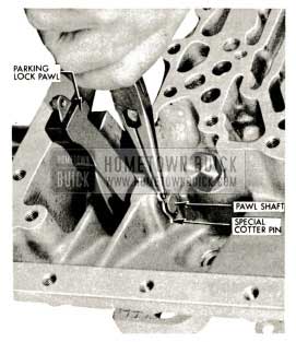
1959 Buick Triple Turbine Transmission – Parking Lock Pawl Removal
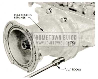
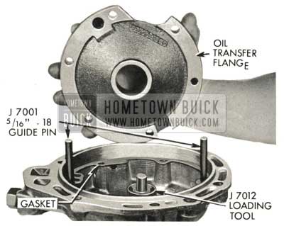
5-45 REAR BEARING RETAINER AND OIL TRANSFER FLANGE: REMOVAL, DISASSEMBLY, INSPECTION AND REASSEMBLY
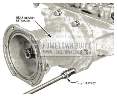
Removal of Rear Bearing Retainer Assembly
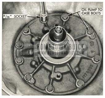
- Remove six rear bearing retainer to case bolts (9/16″ socket).
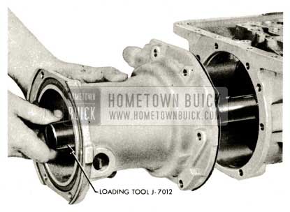
IMPORTANT: A spacer and shim forward of the rear bearing ride on a shoulder of the output shaft. This spacer and shim will fall off the output shaft and lodge in the rear bearing retainer between the rear bearing and oil transfer flange if loading Tool J-7012 is not used.
1959 Buick Triple Turbine Transmission – Remove Bearing Retainer
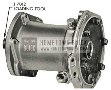
- Insert loading Tool J-7012 in end of output shaft to prevent spacer and shim from falling. Hold loading tool forward while sliding rear bearing retainer and oil transfer flange assembly away from case. Shim and spacer will be transferred from output shaft to loading tool. Leave loading tool in rear bearing retainer assembly. Remove gasket. Examine gasket and gasket sealing area for evidence of leaking or damage.
If rear bearing is not to be inspected or replaced, leave loading tool in place and set assembly aside. Otherwise, proceed with rear bearing retainer-oil transfer flange disassembly.
1959 Buick Triple Turbine Transmission – Loading Tool J-7012
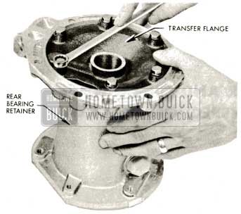
Rear Bearing Retainer-Oil Transfer Flange Disassembly, Inspection and Reassembly
- Remove six oil transfer flange to rear bearing retainer bolts (1/2″ wrench).
1959 Buick Triple Turbine Transmission – Oil Transfer Flange
Examine gasket for evidence of leaking and examine transfer flange bore for evidence of scuffing or galling by oui1put shaft oil rings.
1959 Buick Triple Turbine Transmission – Remove Loading Tool J-7012
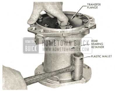
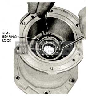
- Remove select fit shims and spacer from rear bearing retainer.
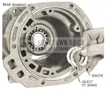
1959 Buick Triple Turbine Transmission – Select Fit Shims
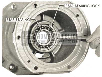
1959 Buick Triple Turbine Transmission – Rear Bearing Lock
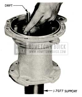
1959 Buick Triple Turbine Transmission – Support Rear Bearing Retainer Web
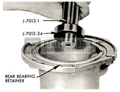
1959 Buick Triple Turbine Transmission – Rear Bearing Retainer
Refer to paragraph 5-49 for output shaft end play adjustment.
Refer to paragraph 5-49 for installation of rear bearing retainer assembly.
1959 Buick Triple Turbine Transmission – Install Rear Bearing Lock
5-46 OUTPUT SHAFT, GEAR TRAIN, FIRST TURBINE SHAFT AND CLUTCHES: REMOVAL, DISASSEMBLY, INSPECTION AND REASSEMBLY
Removal of Output Shaft Assembly
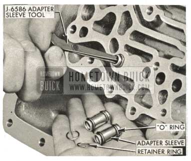
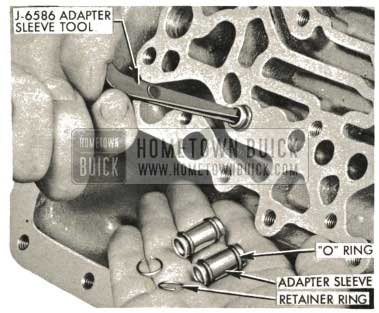
- Remove three of the four adapter sleeves with retaining rings and “O” rings using J-6586 Adapter Sleeve Tool.
1959 Buick Triple Turbine Transmission – Installation of Adapter Sleeves
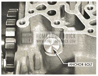
1959 Buick Triple Turbine Transmission – Output Shaft Support Anchor Bolt
NOTE: No retaining ring.
1959 Buick Triple Turbine Transmission – Adapter Sleeve
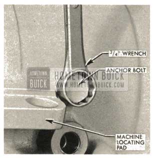
- Remove second output shaft support anchor bolt forward of ratchet wheel (inside case) (3/4″socket).
1959 Buick Triple Turbine Transmission – Install Inner Anchor Bolt
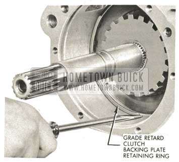
1959 Buick Triple Turbine Transmission – Install Grade Retard Clutch Backing Plate Retaining Ring
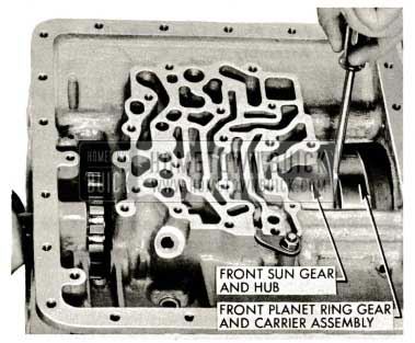
1959 Buick Triple Turbine Transmission – Front Sun Gear and Hub
NOTE: The hammering may dislodge the reverse clutch plates, spring and pressure plate. If so, remove and set them aside.
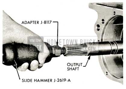
1959 Buick Triple Turbine Transmission – Install Slide Hammer J-2619-A
- After assembly has been moved part way with slide hammer, remove slide hammer and lift assembly from case and set on bench.
1959 Buick Triple Turbine Transmission – Remove Slide Hammer
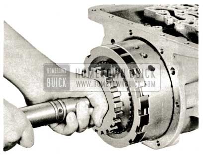
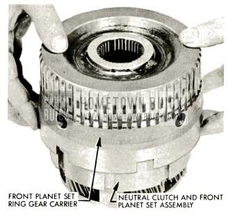
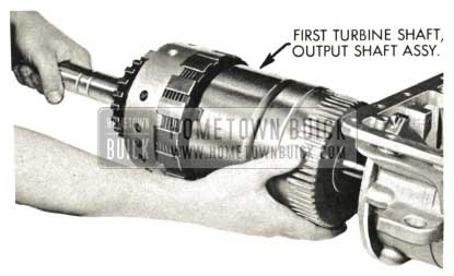
Removal of First Turbine Shaft and Front Planet Set-Neutral Clutch Assembly
- Remove first turbine shaft and front planet set-neutral clutch assembly. Remove needle thrust bearing and cupped race (front planet ring gear carrier to reaction flange hub). This bearing and race may have been removed with front pump assembly.
NOTE: First turbine shaft may have been removed with output shaft.
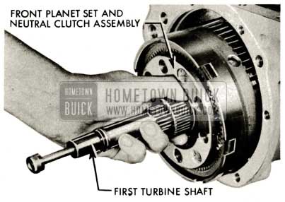
1959 Buick Triple Turbine Transmission – First Turbine Shaft
Removal of Reverse Clutch Plates, Pressure Plates and Spring
- Remove reverse clutch spring, pressure plate, and clutch plates. Refer to Paragraph 5-48 for reverse clutch plate inspection and installation.
NOTE: If case is to be replaced, transfer stator control lever, shaft, and bearing and begin reassembly. Refer to Paragraph 5-47.
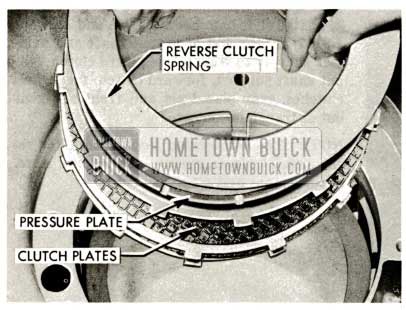
1959 Buick Triple Turbine Transmission – Reverse Clutch Spring
First Turbine Shaft Disassembly, Inspection and Reassembly
- Slide first turbine shaft rearward out of neutral clutch and front planet set assembly if it was not removed with output shaft assembly.
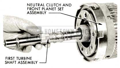
1959 Buick Triple Turbine Transmission – Slide First Turbine Shaft
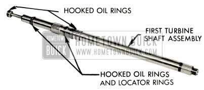
1959 Buick Triple Turbine Transmission – Hooked Oil Rings and Locator Rings
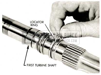
1959 Buick Triple Turbine Transmission – Locator Ring
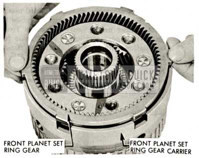
Disassembly, Inspection and Reassembly of Front Planet Set Neutral Clutch Assembly
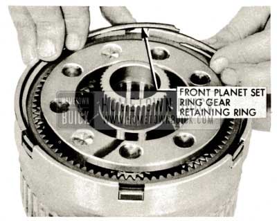
- Remove front planet set ring gear retaining ring using a screwdriver to pry out of groove in front ring gear carrier.
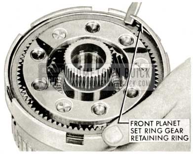
1959 Buick Triple Turbine Transmission – Front Planet Set Ring Gear
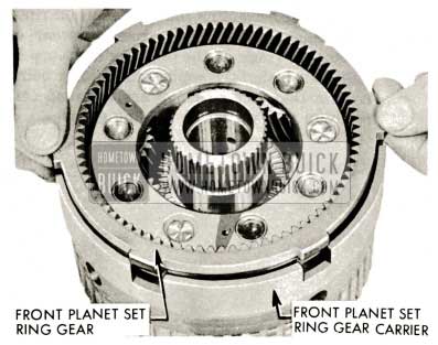
1959 Buick Triple Turbine Transmission – Front Planet Set Ring Gear Carrier
1959 Buick Triple Turbine Transmission – Ring Gear Carrier
1959 Buick Triple Turbine Transmission – Check Clearance
1959 Buick Triple Turbine Transmission – Tanged Bronze Thrust Washer
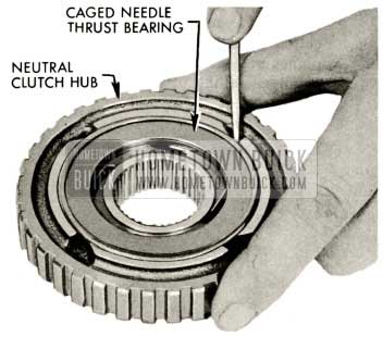
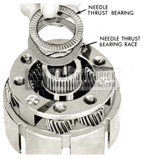
1959 Buick Triple Turbine Transmission – Caged Needle Thrust Bearing
NOTE: Be certain needle thrust bearing is installed squarely in neutral clutch hub and after installation, rotate race to check for free operation. Race must operate freely.
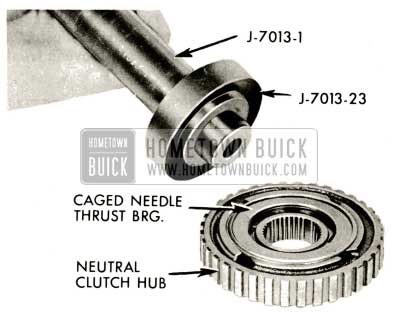
1959 Buick Triple Turbine Transmission – Caged Needle Bearing
- Remove retaining ring from neutral clutch backing plate to front planet set carrier using a screwdriver to pry ring out of groove in front planet set carrier.
NOTE: Neutral clutch backing plate retaining ring is of heavier cross section than clutch spring retaining ring.
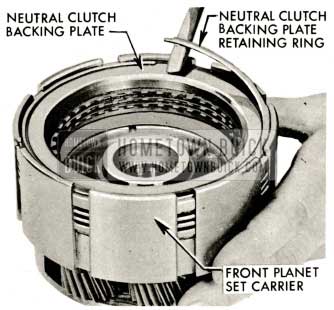
1959 Buick Triple Turbine Transmission – Neutral Clutch Backing Plate
- Remove neutral clutch backing plate, clutch plates and pressure plate from front planet set carrier. Examine plates for heat damage, galling or excessive wear.
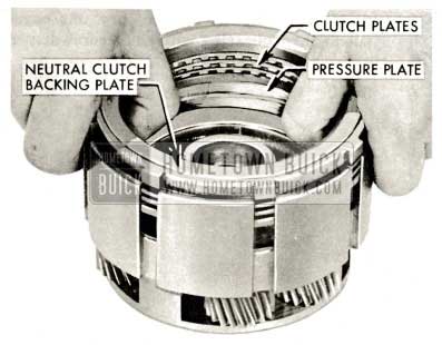
1959 Buick Triple Turbine Transmission – Clutch Plates
NOTE : Neutral clutch spring retaining ring is smaller in cross section than the backing plate retaining ring.
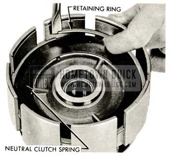
1959 Buick Triple Turbine Transmission – Retaining Ring
- Remove neutral clutch spring from front planet carrier. Examine spring for heat damage, cracks, or excessive wear.
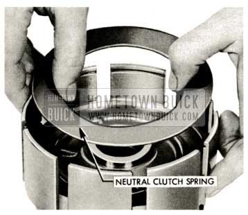
1959 Buick Triple Turbine Transmission – Neutral Clutch Spring
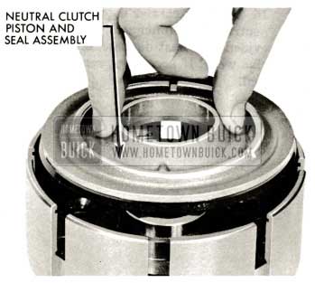
1959 Buick Triple Turbine Transmission – Neutral Clutch Piston and Seal Assembly
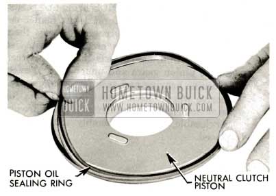
1959 Buick Triple Turbine Transmission – Piston Oil Sealing Ring
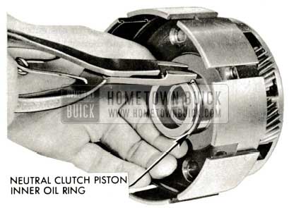
1959 Buick Triple Turbine Transmission – neutral Clutch Piston Inner Oil Ring
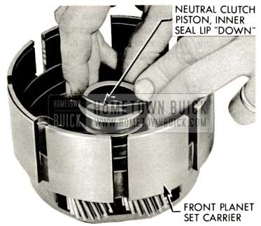
1959 Buick Triple Turbine Transmission – Neutral Clutch Piston
1959 Buick Triple Turbine Transmission – Remove Needle Thrust Bearing Race
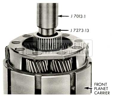
1959 Buick Triple Turbine Transmission – Front Planet Carrier
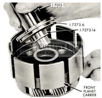
1959 Buick Triple Turbine Transmission – Installer J-7273-14
1959 Buick Triple Turbine Transmission – neutral Clutch Piston Inner Oil Ring
1959 Buick Triple Turbine Transmission – Neutral Clutch Piston
1959 Buick Triple Turbine Transmission – Piston Oil Sealing Ring
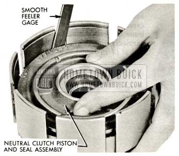
1959 Buick Triple Turbine Transmission – Smooth Feeler Gage
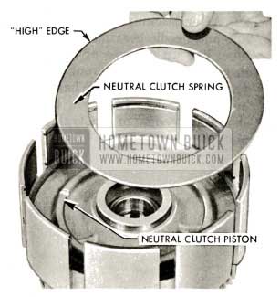
1959 Buick Triple Turbine Transmission – Install Neutral Clutch Spring
NOTE : The neutral clutch spring retaining ring is smaller in cross section than the backing plate retaining ring although both have the same O.D.
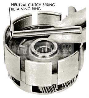
1959 Buick Triple Turbine Transmission – Install Neutral Clutch Spring Retaining Ring
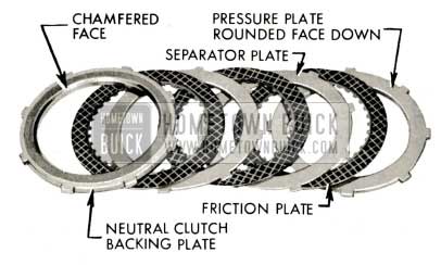
- Install clutch plate pack with rounded face of pressure plate toward spring, then lubricate and install friction plate, separator plate, etc., and chamfered face of clutch backing plate “up” and on top.
NOTE: All clutch plates in neutral clutch pack are fiat, three friction plates and two separator plates.
NOTE: It is important that all plates be lubricated with automatic transmission oil during assembly.
1959 Buick Triple Turbine Transmission – Install Clutch Plate
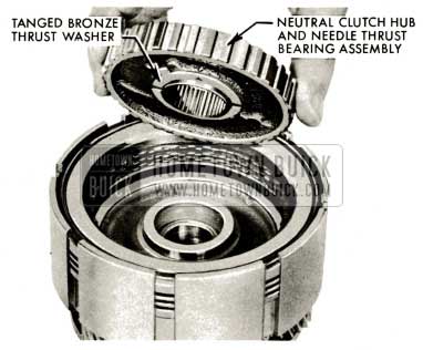
- After sticking bronze thrust washer to hub and needle bearing assembly with heavy lube, line up grooves of friction plates and install hub in bore of front planet set carrier (needle bearing up). When neutral clutch hub is correctly installed, it will be below chamfered edge of neutral clutch backing plate.
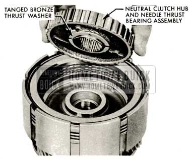
1959 Buick Triple Turbine Transmission – Neutral Clutch Hub
NOTE: The neutral clutch backing plate retaining ring is heavier in cross section than the clutch spring retaining ring although both have the same O.D. Care should be taken to be sure the heavier of the two rings is installed above the backing plate as shown.
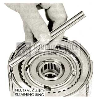
1959 Buick Triple Turbine Transmission – Install Neutral Clutch Retaining Ring
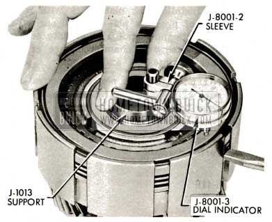
- Check clearance in neutral clutch pack. Use a dial indicator with support J-1013 resting on hub. Set plunger of dial indicator on backing plate. Force plate pack down solidly with fingers and note reading. Force plate pack up with screwdriver between neutral clutch spring snap ring and pressure plate. Note reading. Difference between two readings (clearance) should be between .010″ and .060″.
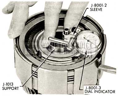
1959 Buick Triple Turbine Transmission – Dial Indicator
1959 Buick Triple Turbine Transmission – Install Front Ring Gear Carrier
1959 Buick Triple Turbine Transmission – Install Front Planet Set Ring Gear
1959 Buick Triple Turbine Transmission – Install Ring Gear Retaining Ring
NOTE: No race on top of needle bearing. Front of front sun gear acts as race. This bearing and race are smaller in J.D. and O.D. than the bearings used in the turbine build-up. Care should be used to avoid interchanging these bearings and races.
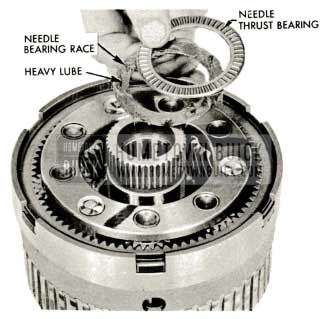
1959 Buick Triple Turbine Transmission – Needle Bearing Race
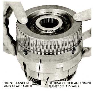
- Invert assembly. Examine cupped needle bearing race; or worn or scored, replace it. Install upper needle bearing race on front planet ring gear carrier, or set it aside for installation with reaction shaft and flange assembly. (Paragraph 5-48)
NOTE: This race may have remained on rear of stator reaction shaft when transmission was disassembled.
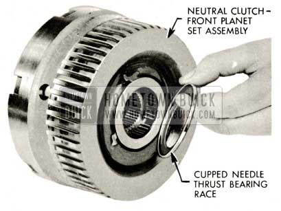
1959 Buick Triple Turbine Transmission – Neutral Clutch Front Planet Set Assembly
- Front planet set-neutral clutch assembly. Refer to Paragraph 5-47 for front planet set-neutral clutch installation.
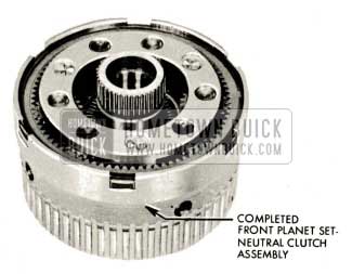
1959 Buick Triple Turbine Transmission – Front Planet Set
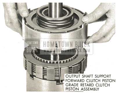
Disassembly, Inspection and Reassembly of Output Shaft Support Assembly
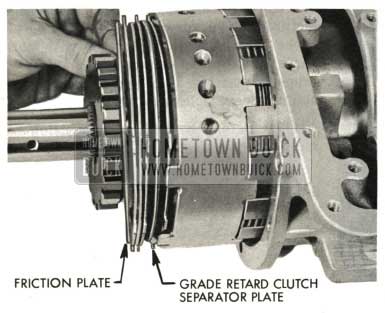
- Slide grade retard clutch backing plate and clutch pack off clutch hub and output shaft. Set clutch pack and backing plate aside. Refer to Par. 5-48 for inspection and installation of grade retard clutch pack.
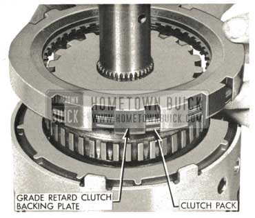
1959 Buick Triple Turbine Transmission – Clutch Pack
1959 Buick Triple Turbine Transmission – Parking Lock Ratchet Wheel
1959 Buick Triple Turbine Transmission – Install Grade Retard Clutch Hub
1959 Buick Triple Turbine Transmission – Install Output Shaft Support Assembly
1959 Buick Triple Turbine Transmission – Install Forward Clutch Spring
NOTE: W id e chamber on J.D. of piston.
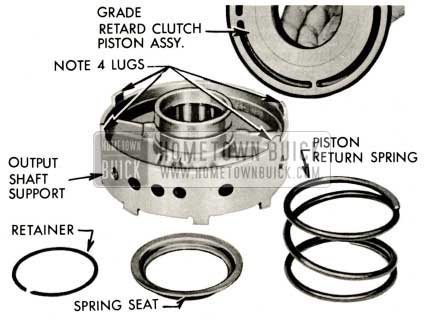
1959 Buick Triple Turbine Transmission – Piston Return Spring
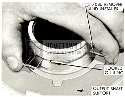
- Remove rubber outer seal from forward clutch piston. Examine rubber outer seal for nicks, tears or excessive wear. Check bore of piston for galling or excessive wear. Replace parts if necessary.
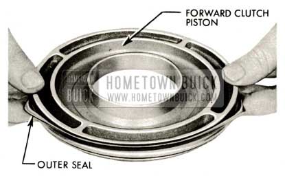
1959 Buick Triple Turbine Transmission – Sealing Ring on Forward Clutch Piston
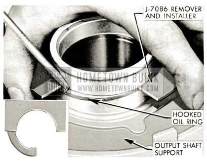
1959 Buick Triple Turbine Transmission – Remove Output Shaft Support
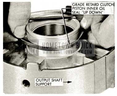
1959 Buick Triple Turbine Transmission – Install Clutch Piston Inner Oil Ring
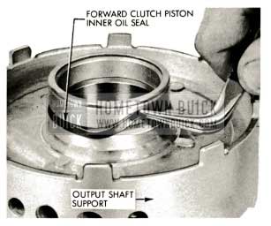
1959 Buick Triple Turbine Transmission – Forward Clutch Piston Inner Oil Seal
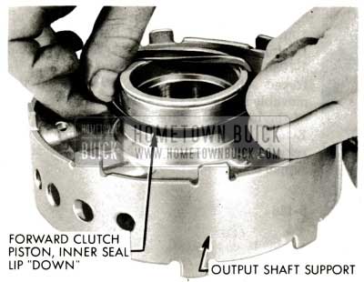
1959 Buick Triple Turbine Transmission – Install Forward Clutch Rubber Inner Oil Seal
1959 Buick Triple Turbine Transmission – Install Grade Retard Clutch Spring
NOTE: No chamber on piston or on bore.
1959 Buick Triple Turbine Transmission – Piston Return Spring
- Remove rubber oil sealing ring from grade retard piston.
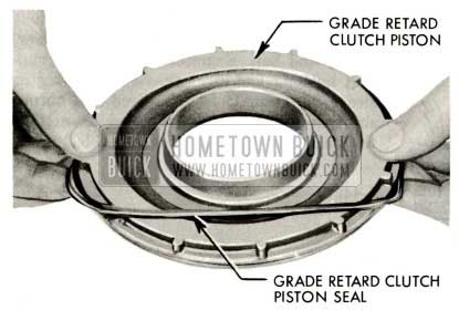
1959 Buick Triple Turbine Transmission – Grade Retard Clutch Piston Seal
1959 Buick Triple Turbine Transmission – Remove Output Shaft Support
1959 Buick Triple Turbine Transmission – Check Output Shaft Support
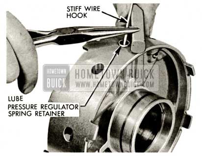
1959 Buick Triple Turbine Transmission – Pressure Regulator Spring Retainer
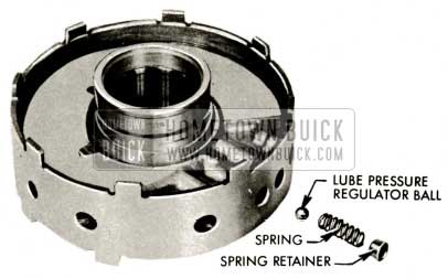
1959 Buick Triple Turbine Transmission – Pressure Regulator Ball
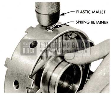
1959 Buick Triple Turbine Transmission – Pressure Regulator Spring Retainer Flush
1959 Buick Triple Turbine Transmission – Sealing Ring on Forward Clutch Piston
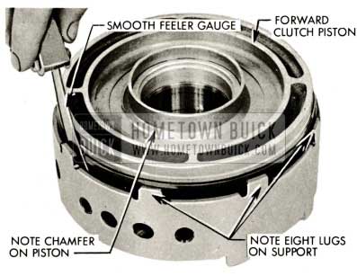
1959 Buick Triple Turbine Transmission – Note Chamber on Piston
1959 Buick Triple Turbine Transmission – Grade Retard Clutch Piston Seal
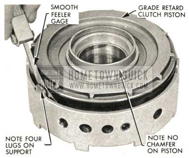
1959 Buick Triple Turbine Transmission – Note Four Lugs on Support
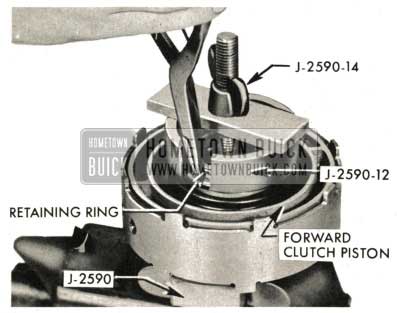
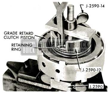
NOTE: Spring, retainer and snap ring are interchangeable with grade retard spring, retainer and snap ring.
1959 Buick Triple Turbine Transmission – Install Forward Clutch Spring
- Install grade retard clutch spring, retainer and snap ring using Tool J-2590-12 and 14 and snap ring pliers. Refer to Par. 5-47 for installation of output shaft support assembly.
1959 Buick Triple Turbine Transmission – Install Grade Retard Clutch Spring
Removal of Forward Clutch Pack; Removal and Inspection of Front Planet Set Sun Gear and Hub
- Slide forward clutch backing plate and clutch pack off forward clutch hub and output shaft. Refer to Par. 5-47 for installation of forward clutch backing plate and clutch pack.
1959 Buick Triple Turbine Transmission – Slide Forward Clutch Backing Plate
1959 Buick Triple Turbine Transmission – Install Front Planet Set Sun Gear
1959 Buick Triple Turbine Transmission – Front Planet Set and Sun Gear Hub Bushing Assembly
1959 Buick Triple Turbine Transmission – Front Planet Set Sun Gear
Disassembly, Inspection and Reassembly of Rear Planet Set
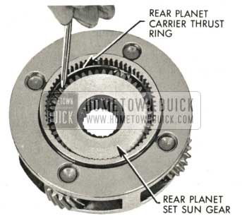
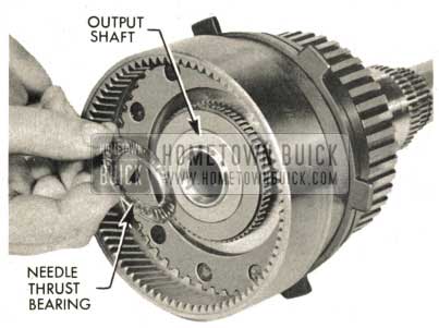
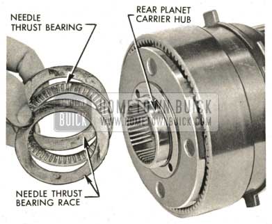
- Remove rear planet set carrier needle thrust bearing and two thrust bearing races from hub of carrier. Examine bearing and races for excessive wear or galling; replace if necessary. Grasp carrier and slide carrier and planet assembly out of rear planet set ring gear. It may be necessary to pry to start out.
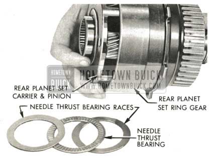
1959 Buick Triple Turbine Transmission – Rear Planet Set Ring Gear
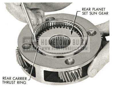
1959 Buick Triple Turbine Transmission – Rear Carrier Thrust Ring
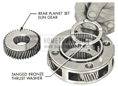
1959 Buick Triple Turbine Transmission – Rear Planet Set Sun Gear
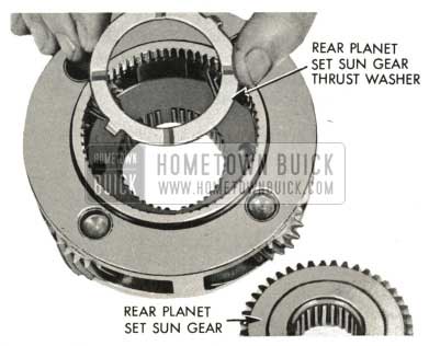
1959 Buick Triple Turbine Transmission – Rear Planet Set Sun Gear Thrust Washer
1959 Buick Triple Turbine Transmission – Rear Planet Carrier Thrust Ring
Inspection of Output Shaft and Output Shaft Bushing, Oil Ring Removal and Replacement
- Remove needle thrust bearing (between rear sun gear and output shaft) from front of output shaft. Examine bearing and front of output shaft for excessive wear or galling. Replace bearing if worn; replace output shaft if galled or rough.
NOTE: No separate needle bearing races used at this point.
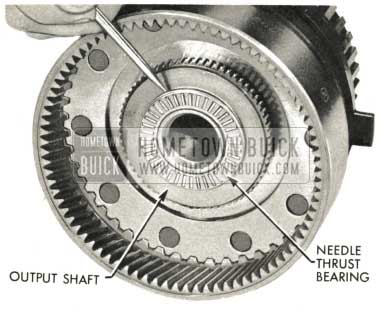
1959 Buick Triple Turbine Transmission – Remove Needle Thrust Bearing
- Slide output shaft forward through grade retard reaction shaft. Needle thrust bearing (between grade retard reaction shaft and output shaft) has no separate races. Remove needle thrust bearing.
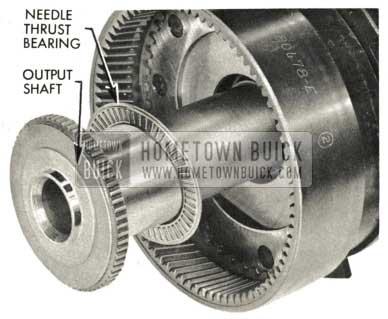
1959 Buick Triple Turbine Transmission – Needle Thrust Bearing Removal
1959 Buick Triple Turbine Transmission – Examine Output Shaft Bushing
1959 Buick Triple Turbine Transmission – Install Output Shaft Bushing
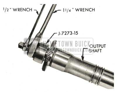
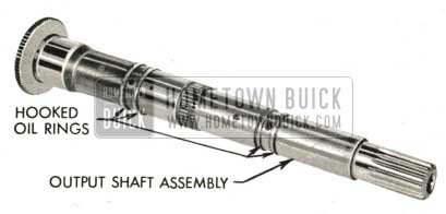
Expand and install four new hooked oil rings in grooves of output shaft.
Blow compressed air through rear end of output shaft to clean small oil bleed hole and screen in output shaft.
1959 Buick Triple Turbine Transmission – Install Hooked Oil Ringes
- Examine needle thrust bearing and bearing surface of output shaft. If ‘ bearing is excessively worn, replace it. If output shaft bearing surface is galled or rough the shaft must be replaced. Apply heavy lube to output shaft to grade retard reaction shaft needle thrust bearing (1 3/4″ I.D. x 2 1/2″ O.D.) and place in position on output shaft. Refer to Par. 5-47 for output shaft installation.
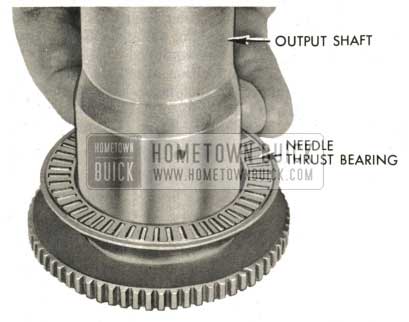
1959 Buick Triple Turbine Transmission – Examine Needle Thrust Bearing
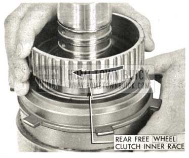
Disassembly, Inspection and Reassembly of Grade Retard Clutch Reaction Shaft and Free Wheel Clutch Assembly
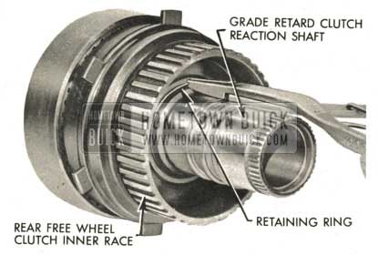
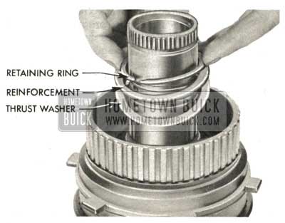
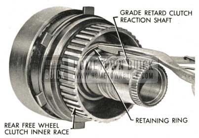
- Expand and remove rear free wheel inner race to grade retard reaction shaft retaining ring.
1959 Buick Triple Turbine Transmission – Remove Rear Fee Wheel Inner Race
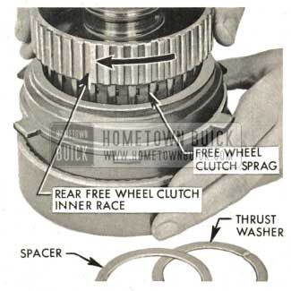
1959 Buick Triple Turbine Transmission – Free Wheel Clutch Sprag
1959 Buick Triple Turbine Transmission – Rear Free Wheel Inner Face
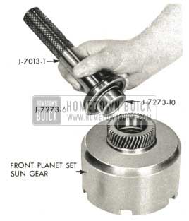
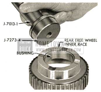
1959 Buick Triple Turbine Transmission – Install Free Wheel Clutch Inner Race Bushing
1959 Buick Triple Turbine Transmission – Remove Free Wheel Clutch Sprag
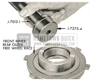
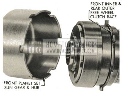
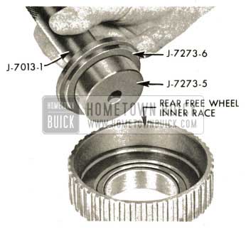
1959 Buick Triple Turbine Transmission – Examine Front Inner and Rear Outer Free Wheel Clutch Race Bushing
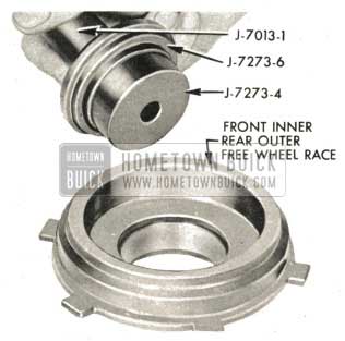
1959 Buick Triple Turbine Transmission – Install Front Inner and Rear Outer Free Wheel Clutch Race Bushing
1959 Buick Triple Turbine Transmission – Examine Rear Planet Set Ring Gear
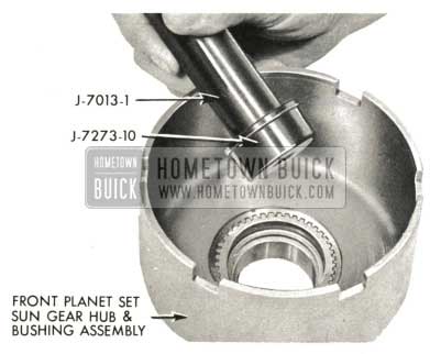
1959 Buick Triple Turbine Transmission – Examine Front Grade Retard Reaction Shaft Bushing
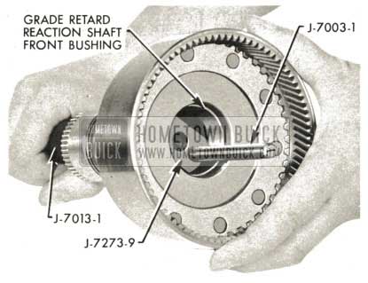
1959 Buick Triple Turbine Transmission – Insert J-7013-1 Handle
1959 Buick Triple Turbine Transmission – Drive out Bushing
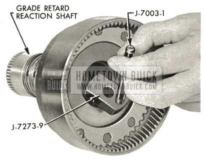
1959 Buick Triple Turbine Transmission – Install Grade Retard Reaction Shaft
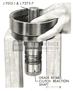
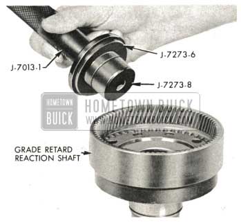
1959 Buick Triple Turbine Transmission – Examine Grade Retard Reaction Shaft
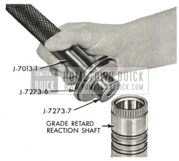
1959 Buick Triple Turbine Transmission – Install Grade Retard Reaction Shaft Rear Bushing
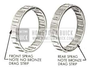
1959 Buick Triple Turbine Transmission – Front Free Wheel Clutch Sprags
NOTE: Extended inner cage “down.”
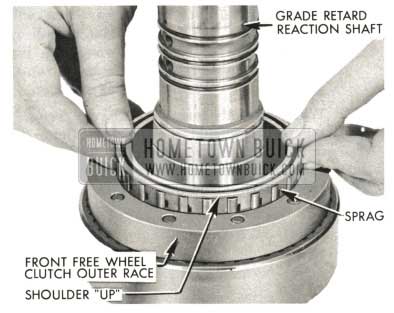
1959 Buick Triple Turbine Transmission – Grade Retard Reaction Shaft
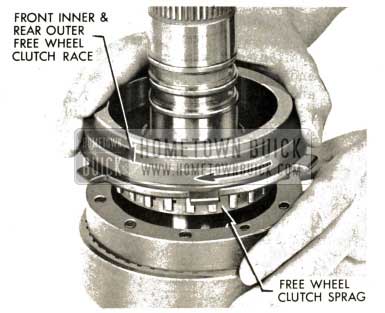
- Lubricate and insert front free wheel clutch inner race into sprag while rotating clockwise. The inner race must rotate freely on clockwise rotation and lock on counterclockwise rotation. When correctly installed, the front inner free wheel race will be approximately 1/16 ” from front outer race.
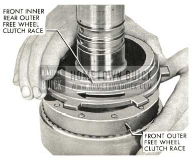
1959 Buick Triple Turbine Transmission – Front Inner Rear Outer Free Wheel Clutch Race
NOTE: Bronze drag strips on rear sprag.
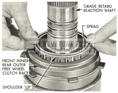
1959 Buick Triple Turbine Transmission – Lubricate Rear Free Wheel Clutch Sprag
- Lubricate and insert rear free wheel clutch inner race-forward clutch hub into sprag while rotating clockwise. The inner race must rotate freely on clockwise rotation and lock on counterclockwise rotation.
- When correctly installed, the rear free wheel inner race . should contact front inner rear outer race. If approximately 1/8″ clearance exists’ rear inner race may be hanging up on bronze strip at bottom of sprag assembly.
1959 Buick Triple Turbine Transmission – Insert Rear Free Wheel Clutch
1959 Buick Triple Turbine Transmission – Assemble Rear Free Wheel Clutch
1959 Buick Triple Turbine Transmission – Install Retaining Ring
5-47 OUTPUT SHAFT, GEAR TRAIN, FIRST TURBINE SHAFT AND CLUTCHES: ASSEMBLY AND INSTALLATION
Assembly of Output Shaft and Grade Retard Reaction Shaft and Free Wheel Clutch Assembly
- Liberally lubricate grade retard reaction shaft bushings and slide shaft and free wheel-clutch assembly over output shaft with lubricated needle thrust bearing in place.
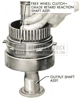
1959 Buick Triple Turbine Transmission – Output Shaft Assembly
NOTE: No separate races used at this location.
1959 Buick Triple Turbine Transmission – Install Needle Thrust Bearing
Assembly of Rear Planet Set and Front Sun Gear and Hub
- Insert rear planet set and sun gear assembly into rear planet ring gear assembly.
1959 Buick Triple Turbine Transmission – Rear Planet Set Ring Gear
1959 Buick Triple Turbine Transmission – Rear Planet Carrier Hub
1959 Buick Triple Turbine Transmission – Install Front Planet Set Sun Gear
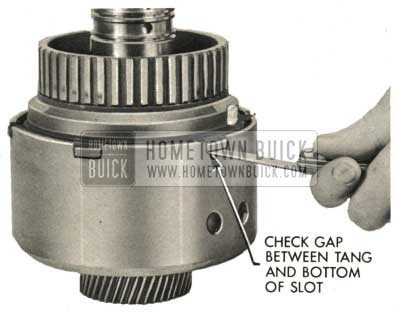
1959 Buick Triple Turbine Transmission – Check Gap
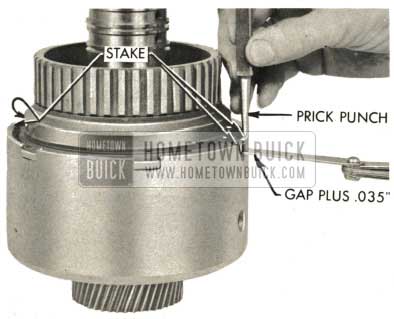
1959 Buick Triple Turbine Transmission – Prick Punch
Inspection and Assembly of Forward Clutch Backing Plate and Clutch Pack
- Examine the forward clutch plates. If they are worn, scored or burned, replace them. Forward clutch friction plates when new are 098″ to .102″ thick. Plates worn thinner than .088″ thick should be replaced.
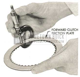
1959 Buick Triple Turbine Transmission – Forward Clutch Friction Plate
1959 Buick Triple Turbine Transmission – Forward Clutch Separator Plate
Assembly of Output Shaft Support Assembly
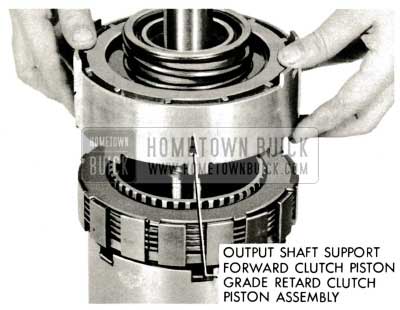
- Lube and install output shaft support assembly on output shaft, eight lugs down and four lugs toward end of output shaft. Engage eight lugs in wide slots of forward clutch backing plate.
NOTE: It is important that the output shaft to output shaft support bushing be lubricated during assembly.
1959 Buick Triple Turbine Transmission – Output Shaft Support
Assembly of Grade Retard Clutch Hub, Bearing and Parking Lock Ratchet Wheel
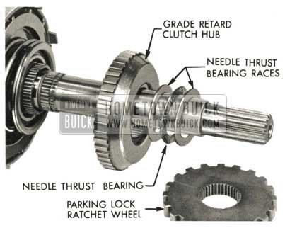
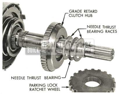
- Install grade retard clutch hub, needle thrust bearing (1 1/2″ I.D. x 2 3/16″ O.D.) and two thrust bearing races, one on each side of needle thrust bearing.
NOTE : Lube bearing with automatic transmission oil.
1959 Buick Triple Turbine Transmission – Grade Retard Clutch Hub
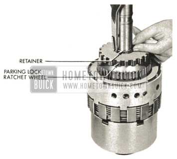
- Slip on parking lock ratchet wheel. Expand and install retaining ring solidly in groove of output shaft.
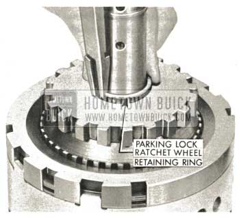
1959 Buick Triple Turbine Transmission – Examine Parking Lock Ratchet Wheel
Assembly of First Turbine Shaft
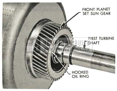
- Lube oil rings on first turbine shaft, rotate shaft to line up splines and insert in output shaft assembly until last oil ring is inside front planet set sun gear.
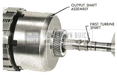
1959 Buick Triple Turbine Transmission – Assembly of First Turbine Shaft
1959 Buick Triple Turbine Transmission – First Turbine Shaft Installation
Assembly of Front Planet Set Neutral Clutch Assembly
- Assemble front planet set-neutral clutch assembly to front sun gear. Make sure front sun gear fully meshes with front planet set.
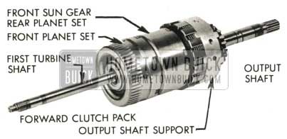
1959 Buick Triple Turbine Transmission – Assembly of Front Planet Set
Installation of Output Shaft-First Turbine Shaft Assembly and Grade Retard Clutch Pack and Backing Plate
- Liberally lubricate inside of case in output shaft support area after making certain there is no dirt or burrs present. Lift assembly carefully. Do not lift by or put any weight on first turbine shaft. Start assembly into rear end of case.
1959 Buick Triple Turbine Transmission – Install First Turbine Shaft Installation
NOTE: Before proceeding with installation, read the following FIVE steps:
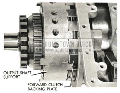
1959 Buick Triple Turbine Transmission – Outer Shaft Support
- Examine the grade retard clutch plates. If they are scored, burned or worn excessively, replace them. Grade retard clutch friction plates are .075″ to .080″ thick when new. Plates worn to .065″ must be replaced.
1959 Buick Triple Turbine Transmission – Installation of Reverse Clutch Pack
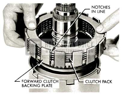
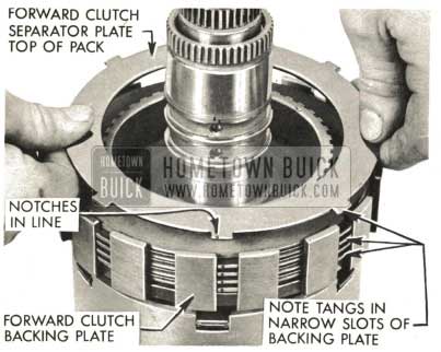
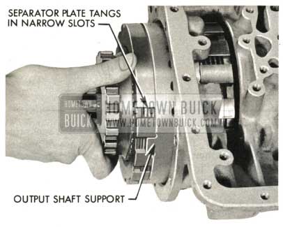
NOTE: If one narrow tang of the separator plates is notched it is unnecessary to check the plates for dish. Install the notches in line in same narrow slot of backing plate.
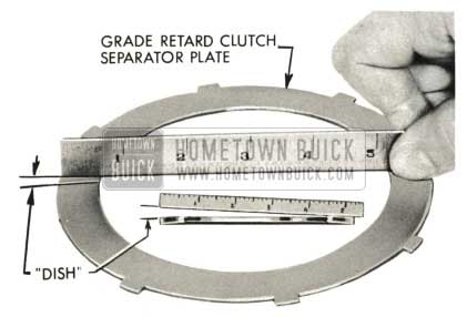
1959 Buick Triple Turbine Transmission – Grade Retard Clutch Separator Plate
- Lubricate and install grade retard clutch separator plate next to piston with center tang of three tangs between lugs of support, then friction plate, separator plate and so on, until three separator plates and three friction plates are installed.
1959 Buick Triple Turbine Transmission – Install Grade Retard Clutch Separator Plate
CAUTION: Maintain hand pressure forward on grade retard clutch backing plate at all times until assembly is correctly positioned in case and backing plate retainer ring is installed. If backing plate is allowed to separate from support, clutch pack will fall out of position and complete assembly must be removed from case and reassembled according to instructions. Do not push assembly into case farther than is necessary to install grade retard clutch backing plate retaining ring.
1959 Buick Triple Turbine Transmission – Install Grade Retard Clutch Backing Plate
- Install grade retard clutch backing plate retaining ring solidly in groove of case.
1959 Buick Triple Turbine Transmission – Install Grade Retard Clutch Backing Plate Retaining Ring
Installation of Adapter Sleeves and Anchor Bolts
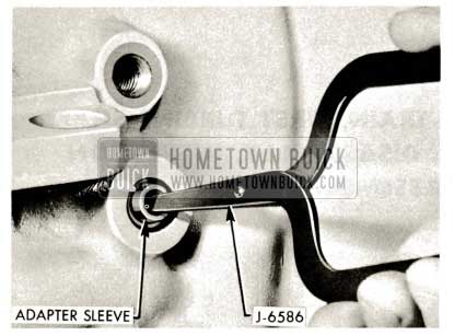
- Use smooth punch inserted in anchor bolt hole to accurately line up oil sleeve adapter holes in support with holes in case. Do not use oil adapter sleeve holes for this purpose.
Lube and install three adaptor sleeves with new O-rings into valve body portion of transmission case using Tool J-6586. Push down firmly to seat adapter sleeves in output shaft support. Install retainer rings above the O-ring sleeve assemblies using a screwdriver to seat retainer rings against sleeve assemblies.
NOTE: Center adapter sleeve does not enter case as far as outer two.
1959 Buick Triple Turbine Transmission – Adapter Sleeve Retainer Ring
- Lube and install fourth adapter sleeve with new O-rings at oil cooler return line location using Tool J-6586. Oil adapter sleeve retainer ring is not used at this location.
1959 Buick Triple Turbine Transmission – Adapter Sleeve
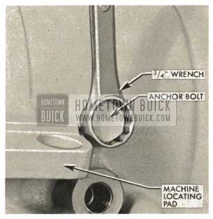
1959 Buick Triple Turbine Transmission – Install Outer Anchor Bolt
1959 Buick Triple Turbine Transmission – Install Inner Anchor Bolt
Installation of Parking Lock Pawl, Pawl Shaft and Retaining Pin
- If parking lock pawl and shaft were removed, install parking lock pawl, pawl shaft and retaining pin.
1959 Buick Triple Turbine Transmission – Parking Lock Pawl Removal
5-48 INSTALLATION OF REVERSE CLUTCH PACK AND OIL PUMPREVERSE CLUTCH PISTON REACTION SHAFT AND FLANGE ASSEMBLY
Inspection and Installation of Reverse Clutch Pack
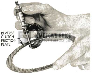
- Inspect reverse clutch plates. If they are scored, burned, or excessively worn, replace them. Reverse clutch friction plates when new are .098″ to .102″ thick. Plates worn to .088″ thick must be replaced.
1959 Buick Triple Turbine Transmission – Installation of Reverse Clutch Pack
NOTE: If one tang of reverse clutch separator plates is notched, it is not necessary to check plates for dish; install plates with notches in line in same slot of backing plate.
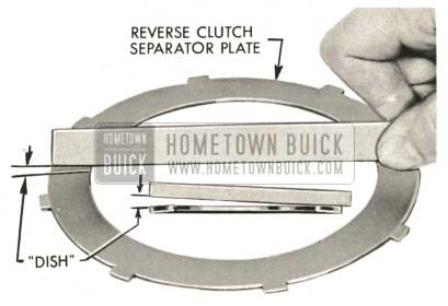
1959 Buick Triple Turbine Transmission – Reverse Clutch Separator Plate
- With transmission front end “up” lubricate and install a reverse clutch friction plate into reverse clutch backing plate, then a separator “dished” same as first, then last friction plate. Install reverse clutch pressure plate, rounded edge up and reverse clutch spring, center high edge up.
NOTE: Both reverse clutch separator plates must be “dished” same way.
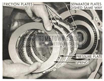
1959 Buick Triple Turbine Transmission – Pressure Plate
Installation of Oil Pump-Reverse Clutch Piston-Reaction Shaft and Flange Assembly
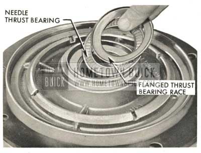
- Apply heavy lube to needle thrust bearing and flanged race and stick them to rear of reaction flange hub.
NOTE : The flanged needle thrust bearing race may be assembled on top of front planet ring gear carrier, whichever may be most convenient.
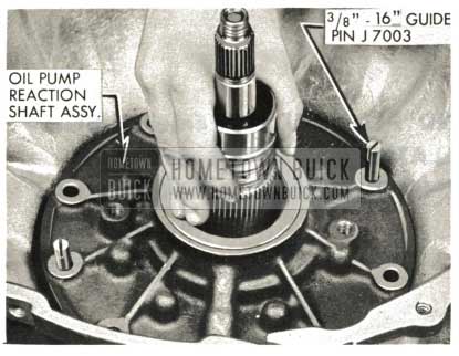
1959 Buick Triple Turbine Transmission – Installation of Oil Pump
- Install new reaction flange to case gasket in transmission case. Be absolutely certain that gasket holes line up , properly. Install two 3/8″-16 Guide Pins J-7003 in transmission case, liberally lube rubber seal on pump assembly with heavy lube, and slip pump and reverse clutch piston assembly into case so that the three closely spaced holes are at bottom of case. Tap the assembly evenly and solidly in position in case with brass drift and plastic hammer.
CAUTION: Never attempt to d raw the pump assembly into position with pump bolts as transmission case threads will almost certainly be stripped.
1959 Buick Triple Turbine Transmission – Install Reaction Flange
- Install eight pump to case bolts and draw down lightly.
1959 Buick Triple Turbine Transmission – Install Pump to Case Bolts
1959 Buick Triple Turbine Transmission – Remove Guide Pins
5-49 OUTPUT SHAFT END PLAY MEASUREMENT AND ADJUSTMENT. INSTALLATION OF REAR BEARING RETAINER-OIL TRANSFER FLANGE ASSEMBLY
Output Shaft End Play Measurement and Adjustment
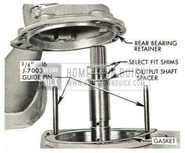
- If oil transfer flange and loading tool were removed from rear bearing retainer, install .120″ spacer on output shaft with shims removed from output shaft when transmission was disassembled. Install two guide pins 3/8″-16, J-7003, gasket and rear bearing retainer without oil transfer flange.
If transfer flange and loading tool were not removed from rear bearing retainer, proceed with step 3 of sub-paragraph b below.
1959 Buick Triple Turbine Transmission – Output Shaft End Play Adjustment
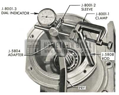
- Check output shaft end clearance with rear bearing retainer bolted to case with at least two bolts as shown and transmission upside down. Tap several times on output shaft to squeeze out lube used on thrust bearings during assembly. Use J-8001-3 Dial Indicator, Tool 5804 threaded into output shaft and Tool J-5808 threaded into rear bearing retainer. Use pry bar under edge of J-5804 to move output shaft. End play should be .005″ to .020″. If output shaft end clearance is less than .005″, remove rear bearing retainer and install a thinner shim on output shaft. If output shaft end clearance is more than .020″, remove rear bearing retainer and install a thicker shim.
1959 Buick Triple Turbine Transmission – Check Output Shaft
1959 Buick Triple Turbine Transmission – Remove End Play Gage Setup
1959 Buick Triple Turbine Transmission – J-7012 Loading Tool
Installation of Rear Bearing Retainer Oil Transfer Flange Assembly
- With rear bearing retainer to case gasket in place assemble rear bearing retainer-oil transfer flange assembly to case. Hold loading tool forward while sliding bearing. retainer onto output shaft to transfer spacer and shims onto output shaft.
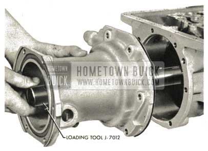
1959 Buick Triple Turbine Transmission – Left Loading Tool J-7012
1959 Buick Triple Turbine Transmission – Remove Loading Tool
If end clearance is not within limits, rear bearing retainer and transfer flange must be removed and end clearance corrected as outlined in step 2 of subparagraph a, above.
1959 Buick Triple Turbine Transmission – Loading Tool J-7012
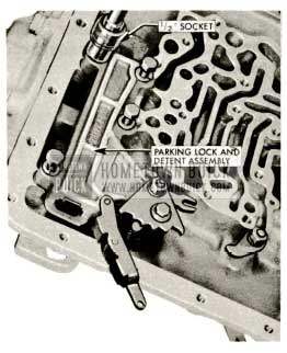
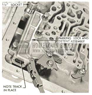
5-50 INSTALLATION OF MANUAL CONTROL AND PARKING LOCK AND DETENT ASSEMBLY
- Install properly assembled parking lock mechanism to case with four bolts 5/16 “-18. Torque bolts to 15-20 ft. lbs. (1/2” socket).
1959 Buick Triple Turbine Transmission – Install Parking Lock Mechanism
1959 Buick Triple Turbine Transmission – Install Parking Lock Pawl
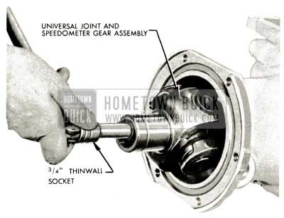
5-51 INSTALLATION OF UNIVERSAL JOINT, TORQUE BALL AND TORQUE BALL RETAINERS
- Engage parking lock pawl. Install U-joint and speedo gear assembly with special drilled U-joint bolt, lock washer and plain washer using 3/4″ thin wall socket. Torque to 50-55 ft. lbs.
1959 Buick Triple Turbine Transmission – Universal Joint
1959 Buick Triple Turbine Transmission – Install Rear Bearing Retainer
1959 Buick Triple Turbine Transmission – Install Sealing Ring
1959 Buick Triple Turbine Transmission – Install Torque Ball
1959 Buick Triple Turbine Transmission – Install Outer Torque Ball Retainer
1959 Buick Triple Turbine Transmission – Install Torque Ball Bolts
5-52 INSTALLATION OF VALVE BODY ASSEMBLY
- With transmission upside down, use new gasket and carefully install valve body assembly. Engage slot in shift lever with slot and pin in manual control valve.
NOTE: Surface of valve body, gasket, and valve body section of transmission case must be free of dirt.
1959 Buick Triple Turbine Transmission – Installation of Valve Body Assembly
- Install bolts as shown but do not tighten.
1959 Buick Triple Turbine Transmission – Install Bolts
1959 Buick Triple Turbine Transmission – Tighten Valve Body Bolts
5-53 STATOR VALVE, PARKING LOCK AND MANUAL CONTROL VALVE ADJUSTMENT
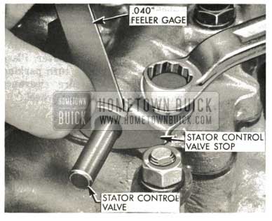
Stator Valve Stop Adjustment
- Slip .040″ feeler gage into position between valve body and valve stop. Press stator valve stop toward valve body and hold in this position by tightening bolts as shown (1/2″ wrench).
1959 Buick Triple Turbine Transmission – Stator Valve Stop Adjustment
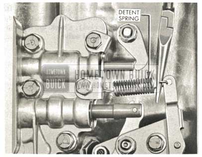
1959 Buick Triple Turbine Transmission – Install Detent Spring
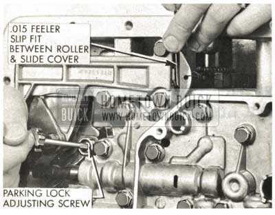
Parking Lock Adjustment
- Loosen parking lock and detent assembly bolts slightly. Tap roller slide cover “in” fully. Retighten bolts.
1959 Buick Triple Turbine Transmission – Parking Lock Adjustment
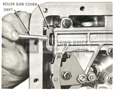
1959 Buick Triple Turbine Transmission – Roller Slide Cover
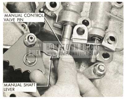
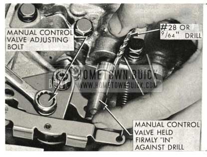
Manual Control Valve Adjustment
- With transmission in “Park” position, (detent plate rotated rearward to last notch) loosen manual control valve adjusting bolt (7/16″ wrench), insert 9/16″ drill between inner edge of first land of manual valve and valve body; hold valve “in” toward valve body with drill in position; at same time hold detent lever solidly in notch, and tighten adjusting bolt with valve in this position.
NOTE: Drill should rest against portion of valve body above valve. If drill is extended too far down, it will rest against a raised boss and be tilted, thus preventing accurate adjustment of the valve.
1959 Buick Triple Turbine Transmission – Manual Control Valve Adjustment
5-54 INSTALLATION OF OIL SCREEN, OIL PAN AND SELECTOR LEVER
- Install oil screen and five oil screen screws.
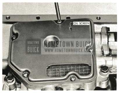
1959 Buick Triple Turbine Transmission – Install Oil Screen
1959 Buick Triple Turbine Transmission – Install Oil Pan Gasket
NOTE : Oil pan gasket must be installed with “sharp corner of gasket at front right corner of pan flange (Transmission upside down and viewed from rear).
- Make sure selector lever shaft seal is properly positioned in shaft bearing. Install lever and nut, being careful not to put any strain on internal linkage while tightening nut.
1959 Buick Triple Turbine Transmission – Selector Lever Shaft Nut
5-55 CONVERTER CLEARANCE MEASUREMENT AND ADJUSTMENT
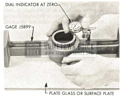
Measurement of Converter Pump Cover Deflection
- “Zero” the converter clearance gauge on a piece of plate glass or surface plate. Tighten plunger set screw. Adjust height of dial indicator so indicator plunger may move “in” at least .100”. Set indicator at zero.
1959 Buick Triple Turbine Transmission – Measurement of Converter Pump
1959 Buick Triple Turbine Transmission – Gauge J5899
1959 Buick Triple Turbine Transmission – Release Plunger Set Screw
1959 Buick Triple Turbine Transmission – Proper Converter Clearance
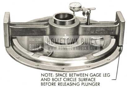
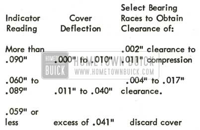
Measurement and Adjustment of Converter Clearance
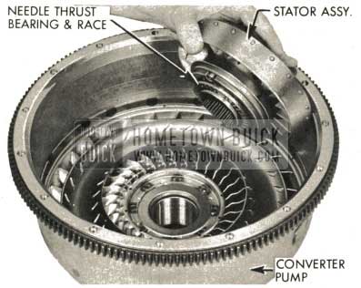
- Set converter pump over hole in bench. Place stator assembly in pump with needle thrust bearing and race in place.
1959 Buick Triple Turbine Transmission – Measurement of Converter Clearance
NOTE: Be certain needle thrust bearing and race s are in place between _second turbine hub and stator assembly.
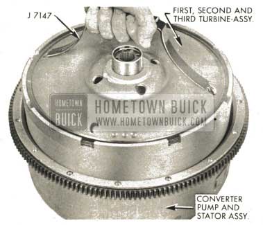
1959 Buick Triple Turbine Transmission – Set First, Second and Third Turbine Assembly
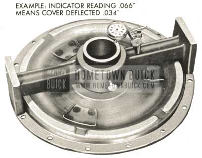
- Place needle thrust bearing and races on top of first turbine disc and hub. Place gage J-5899 in position on top of pump-turbine assembly with small diameter end of gage plunger “up.” Loosen plunger set screw and press plunger down; tighten set screw.
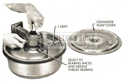
1959 Buick Triple Turbine Transmission – Converter Pump Cover
NOTE: If necessary, an additional bearing race may be used to obtain required clearance. Races are available in .030″, .040″, and .050″ thicknesses.
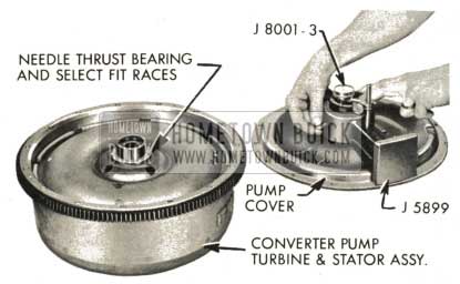
1959 Buick Triple Turbine Transmission – Converter Pump Turbine and Stator Assembly
5-56 INSTALLATION OF CONVERTER
- With transmission front end up, carefully install converter pump in transmission case and rotate to engage lugs of pump hub with oil pump drive gear. Use care when lowering pump into case to avoid damage to pump seal.
1959 Buick Triple Turbine Transmission – Installation of Converter
1959 Buick Triple Turbine Transmission – Stator Assembly
1959 Buick Triple Turbine Transmission – Third Turbine Assemby
1959 Buick Triple Turbine Transmission – First Turbine Hub and Disc
1959 Buick Triple Turbine Transmission – Assemble First Turbine Shaft Nut
1959 Buick Triple Turbine Transmission – Assemble Select Fit Bearing Race
1959 Buick Triple Turbine Transmission – Install O-Ring on Converter Pump
1959 Buick Triple Turbine Transmission – Assemble Converter Pump
NOTE: Only 300M bolts may be used at this location and at the flywheel to ring gear location. 300M bolts may be identified by six radial marks on the bolt head.
NOTE: Under no circumstances is the transmission to be tilted forward after the converter is assembled. The converter assembly will fall out and damage to the first turbine shaft and front planet carrier will result.
1959 Buick Triple Turbine Transmission – Install Converter Pump
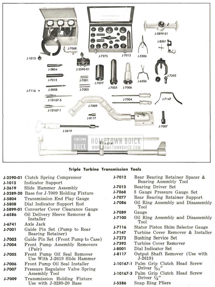
1959 Buick Triple Turbine Transmission Tools
Hello!
Great write up, thank you so much!
Do you know where I could source new frictions ( clutch discs) please?
It’s for a ’58 triple turbine ( flight pitch Dynaflow).
Thank you 🙂