SECTION 4-A 1959 BUICK CLUTCH
4-1 1959 BUICK CLUTCH SPECIFICATIONS
Tightening Specifications
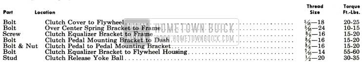
1959 Buick Clutch Tightening Specifications
1959 Buick Clutch Specifications
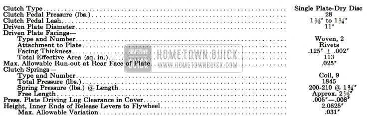
1959 Buick Clutch Specifications
4-2 DESCRIPTION OF 1959 BUICK CLUTCH
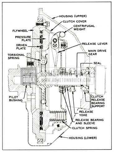
A single plate, dry disc clutch is used in cars equipped with synchromesh transmissions. The 1959 Buick clutch is of conventional design with coil type clutch springs and three release levers. The release levers are non-adjustable. The clutch pressure plate and cover assembly will be serviced only as a complete unit.
1959 Buick Clutch Assembly
The 1959 Buick clutch cover is bolted to the flywheel and three lugs on the pressure plate engage slots in the cover to transmit torque to the plate. Nine clutch springs are located between the cover and the pressure plate. The three clutch release levers are located so that their inner ends are in position to be engaged by the clutch release bearing. The levers pivot on fulcrums bolted to the 1959 Buick clutch cover and on bearings in the three pressure plate lugs. See figure 4-1.
1959 Buick Clutch and Flywheel Assembly
The outer ends of the release levers are weighted so that at higher engine speeds where slipping is liable to occur, centrifugal force causes more pressure to be applied on the pressure plate. The faster the 1959 Buick clutch revolves, the greater the pressure exerted against the 1959 Buick clutch plate, thereby increasing the torque transmitting ability of the clutch. This additional pressure allows the use of a clutch which requires lower foot pressure at the pedal for normal clutch operation.
When the 1959 Buick clutch is in the engaged position, the release levers are clear of the release bearing and the clutch springs cause the pressure plate to clamp the driven plate against the flywheel with sufficient force to transmit power of the engine without slippage. The power drive is from flywheel to clutch cover, cover to pressure plate, and from pressure plate and flywheel to driven plate.
When the 1959 Buick clutch is disengaged, the clutch release bearing presses forward on the inner ends of the release levers which pivot and force the pressure plate rearward against the pressure of clutch springs. The pressure plate is moved rearward far enough to free the driven plate. See figure 4-1.
1959 Buick Clutch Driven Plate
The 1959 Buick clutch driven plate assembly is mounted with a free sliding fit on the transmission main drive gear and is keyed to the gear by ten splines. The front end of the main drive gear is piloted by a ball bearing pressed into a recess on rear end of engine crankshaft. See figure 4-1.
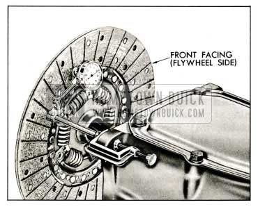
The outer area of the driven plate is divided into segments which are formed in low waves to provide springs between the plate facings and thereby cushion engagement of the 1959 Buick clutch. A woven facing, grooved to give quick release, is riveted to each side of every segment of plate. When the 1959 Buick clutch is fully released, the waved segments cause the facings to spread approximately .050″ and the movement of pressure plate provides an additional clearance of approximately .030″ to assure full release of driven plate. See figure 4-2.
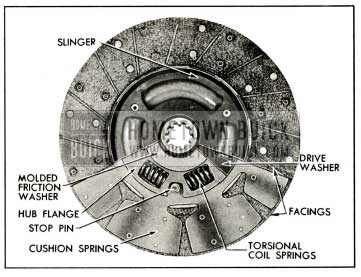
1959 Buick Driven Plate-Transmission Side
The driven plate assembly is designed to prevent torsional periods of the engine from being transmitted to the transmission gears and causing rattle. This is accomplished by driving the plate hub through torsional coil springs and providing frictional dampening by means of molded friction washers.
1959 Buick Clutch Linkage
The 1959 Buick clutch pedal is of the suspended type and pivots on a shaft which extends through brackets bolted to the cowl. This shaft is also used to suspend the standard brake pedal.
(Power brakes are not available on a synchromesh car.) The 1959 Buick clutch pedal returns against a non-adjustable pedal stop under the instrument panel. See Figure 4-3.
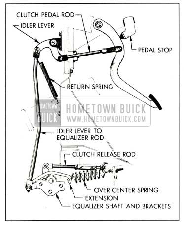
1959 Buick Clutch Linkage
An adjustable pedal rod and clevis extends through the cowl to connect the pedal to an idler lever which pivots in a bracket bolted on the forward side of the cowl. An idler lever to equalizer rod extends downward to the 1959 Buick clutch release equalizer. The equalizer pivots between the engine at one end and the frame at the other. The clutch release rod and adjusting nut extends from the equalizer to the 1959 Buick clutch release yoke. See Figure 4-4.
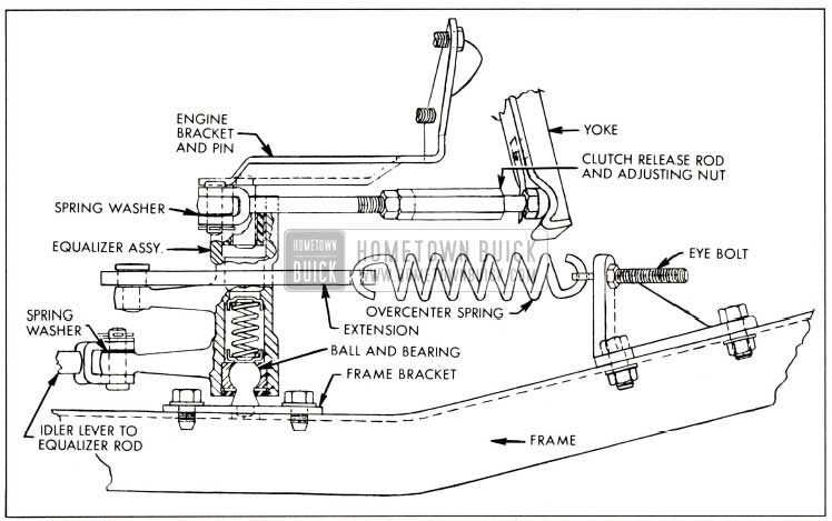
1959 Buick Clutch Release Equalizer
A light pedal return spring extends from the idler lever to the mast jacket bracket. A heavy over center spring and extension is stretched from an eye bolt at the frame to a pin at the equalizer.
The release rod has an adjustable nut. The yoke is held on a ball stud by a U-shaped spring riveted to the yoke. A boot around the yoke provides a flexible closure for the yoke opening in the flywheel housing. The inner end of the yoke is in position to push forward on the release bearing when the 1959 Buick clutch pedal is depressed. A U-shaped spring riveted to the release bearing holds the bearing in contact with the yoke. The release rod length must be adjusted to provide correct clearance between the release bearing and the 1959 Buick clutch release levers (par. 4-4).
The release bearing and sleeve assembly is mounted on a bearing support which encircles the transmission main drive gear. The bearing is filled with lifetime lubricant in production and no further lubrication is required. The bearing support is flared at the rear end to seat in the flywheel housing and is held in place by a spring washer and the outer race of the transmission main drive gear bearing. See Figure 4-1.
4-3 1959 BUICK CLUTCH TROUBLE DIAGNOSIS
Excessive Pedal Pressure
The pressure required to depress 1959 Buick clutch pedal to toe board should not exceed 28 pounds. If pedal pressure is excessive, make certain that pedal rod is not binding where it passes through the cowl. Thoroughly lubricate release equalizer with chassis lubricant. Lubricate all linkage pins with engine oil.
If excessive pedal pressure still exists after release linkage is properly lubricated, lubricate internal working parts of 1959 Buick clutch as described in paragraph 4-4.
1959 Buick Clutch Noise
Squeaking and grinding noises during 1959 Buick clutch pedal operation are usually caused by heavy friction in the release linkage or internal parts of 1959 Buick clutch assembly. Before condemning the release bearing, thoroughly lubricate release equalizer and, if necessary, lubricate internal working parts of clutch as described in paragraph 4-4.
1959 Buick Clutch Grab or Chatter
A very slight amount of oil on driven plate facings will cause 1959 Buick clutch grab and chatter. A new driven plate must be installed if original plate facings contain oil since removal of oil from facings is not practical.
When oil is found on facings, examine pilot bushing, transmission drain back, rear engine bearing, and oil leaks which might drain back into 1959 Buick clutch housing between upper and lower flywheel housings.
Improper variation in height of release levers will cause clutch chatter. See paragraph 4-5 (b).
To correct this condition, the complete 1959 Buick clutch assembly must be replaced, because the release levers are neither adjustable nor available for replacement.
1959 Buick Clutch Drag or Failure to Release
To test for clutch drag or failure to release, depress 1959 Buick clutch pedal to toe board with engine running and shift transmission into low gear. Hold pedal depressed and shift transmission to neutral, wait about 15 seconds with pedal depressed and again shift into low gear. If 1959 Buick clutch is not releasing completely a gear clash will occur.
If test shows that 1959 Buick clutch is not releasing properly, check clutch pedal lash (par. 4-4) and check release linkage for lost motion. Correct as necessary and again test for clutch drag.
If clutch drag cannot be corrected in release linkage, remove clutch and check height of release levers. Check driven plate for oil soaked or cracked facings, also for run-out and free movement on main drive gear (par. 4-6).
1959 Buick Clutch Slipping
First make certain that 1959 Buick clutch pedal is adjusted for specified lash (1 1/8″ to 1 1/4″) and that pedal is not binding. One type of clutch slippage is sometimes wrongly diagnosed as due to weak clutch springs. This slippage occurs during gear shifting and full engagement of the clutch is not obtainable until the engine speed is reduced. After full engagement is obtained no further slippage occurs during acceleration or under full load. This condition is usually due to the clutch driven plate hub sticking on the splines of the transmission main drive gear. Correction can be made by removing the clutch and thoroughly cleaning splines of driven plate and main drive gear then applying a light coating of Lubriplate. Make sure that release lever pins are not binding, and that pressure plate driving lugs are not binding in clutch cover.
4-4 1959 BUICK CLUTCH ADJUSTMENT AND LUBRICATION
Over Center Adjustment
The over center position of the equalizer, once properly adjusted, will remain in adjustment for a considerable time unless the 1959 Buick clutch linkage is disturbed. However, the over center adjustment should be given a quick check each time any 1959 Buick clutch service is necessary.
The over center adjustment is important because when the equalizer position is properly adjusted, the over center spring helps hold the 1959 Buick clutch pedal against its stop. As soon as the pedal is partially depressed, however, the equalizer passes over center and the over center spring helps depress the pedal. This results in a lower pedal pressure. See Figure 4-4.
Check over center adjustment as follows:
- Make sure 1959 Buick clutch pedal returns fully against pedal stop.
- Raise car and measure clearance between over center spring extension and clutch equalizer using a piece of 1/4″ drill rod or other suitable 1,4″ thick spacer.
- If clearance is not approximately 1/4″, the adjustment must be made.
Make over center adjustment as follows:
- With car raised, back-off clutch release rod jam nut and adjusting nut approximately 3/4″. This is to make slack in the linkage so that the pedal rod clevis can be rotated in step 5.
- Place 1/4″ spacer between over center spring extension and equalizer.
- Lower car and back-off pedal rod lock nut under instrument panel.
- Remove clevis pin which fastens 1959 Buick clutch pedal to pedal rod clevis. This allows the equalizer to rotate slightly to its correct position with the over center spring extension against the 1/4″ spacer.
- Rotate pedal rod clevis as necessary for clevis pin to slip in freely with both 1959 Buick clutch pedal and clevis pulled to the rear. See Figure 4-4.
- NOTE: Before clevis will rotate , pedal rod and clevis pin must be pushed forward , taking up slack in linkage .
- Install clevis pin with spring washer, plain washer, and new cotter pin. Tighten pedal rod lock nut.
- Raise car and remove 1/4″ spacer.
- Adjust pedal lash as described in subparagraph b.
1959 Buick Pedal Lash Adjustment
1959 Buick Pedal lash (free pedal) must be adjusted occasionally to compensate for normal wear of clutch facings. As the driven plate wears thinner, pedal lash decreases.
It is very important to maintain pedal lash at all times. Insufficient pedal lash will cause the release bearing to ride against the release levers all of the time, resulting in abnormal wear of these parts. It may also cause clutch slippage and abnormal wear of the driven plate, flywheel, and pressure plate if pressure on the release levers is enough to prevent positive engagement of the 1959 Buick clutch. See Figure 4-4.
Check pedal lash (free pedal) by pushing on the pedal pad with the hand. Do not mistake the tension due to the pedal return spring as an indication of lack of pedal lash. Pedal lash should be 1 1/8″ to 1 1/4″ measured at the pedal pad.
Adjust pedal lash as follows:
- Make certain that return spring pulls 1959 Buick clutch pedal firmly against pedal bumper when pedal is released. If pedal does not contact bumper, check pedal and linkage for binding or lack of lubrication. Check condition of pedal return spring. Check condition of equalizer over center spring and make sure that spring eye bolt is fully tightened. See Figure 4-4.
- With car raised, check over center adjustment as described in subparagraph a. above. Clutch equalizer must be in proper position before pedal lash is adjusted.
- Loosen adjusting nut jam nut on clutch release rod.
- Turn adjusting nut so that when equalizer is rocked over center by hand total free movement at outer end of clutch release yoke is 1/4″.
- This should give correct lash at the pedal. Tighten adjusting nut jam nut.
- Lower car. Check to make sure pedal lash is between 1 1/8″ and 1 1/4″.
Lubrication of 1959 Buick Clutch Internal Parts
Lubrication of 1959 Buick clutch release equalizer and linkage is included in Lubricare every 1000 miles (par. 1-1). Lubrication of clutch internal working parts is usually required only at time 1959 Buick clutch is assembled and installed; however, if lubrication becomes necessary to eliminate squeaks or excessive pedal pressure, proceed as follows:
- Remove flywheel lower housing.
- Disconnect release rod from yoke, unhook boot from opening in flywheel upper housing, and pull yoke outward to disengage it from ball stud. See figure 4-5.
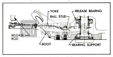
1959 Buick Clutch Release Yoke and Boot
Rotate flywheel until each release lever in turn is in lowest position, then very sparingly oil the release lever fulcrums and sides of release levers. Allow time for any surplus oil to drain off before turning flywheel, to avoid getting oil on driven plate facings. Release lever fulcrums also may be lubricated by spraying with powdered graphite, which will not damage driven plate facings. This may not afford immediate relief but if 1959 Buick clutch is operated while engine is running, after installation of flywheel lower housing, the graphite will work into the bearing surfaces.
- Install flywheel lower housing.
4-5 REMOVAL AND INSTALLATION OF 1959 BUICK CLUTCH
Removal of 1959 Buick Clutch
- Remove rear axle assembly (par. 6-4) and transmission (par. 4-13). Remove flywheel lower housing.
- Disconnect release rod from release yoke and remove yoke boot. See figure 4-5.
- Remove spring washer which retains release bearing support in flywheel housing and remove support and gasket.
- Pull outward on release yoke to free it from the ball stud in flywheel housing and remove yoke and release bearing through bottom of housing. Separate yoke from bearing.
- Mark the 1959 Buick clutch cover and the flywheel with a center punch so that cover can be reinstalled in the same position on flywheel in order to preserve engine balance.
- Loosen each 1959 Buick clutch cover bolt a little at a time in order to relieve clutch spring pressure evenly and avoid distortion of cover. Metal spacers placed between release levers and inner edge of clutch cover will aid removal and later reinstallation by holding clutch springs compressed.
- Support pressure plate and cover assembly while removing the last bolts, then remove the cover assembly and driven plate.
Checking Release Lever Height
Correct release lever height is essential to insure complete release of the 1959 Buick clutch and also to allow smooth, positive engagement of the 1959 Buick clutch. Before reinstalling a clutch pressure plate and cover assembly, release lever height should be checked as follows:
- Mount dial indicator on Support J-1013, set support on flat surface, press indicator stem down against surface until indicator hand has made one revolution, then tighten indicator to support and set indicator to zero. See figure 4-6.
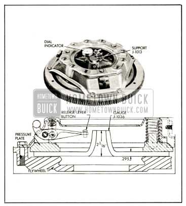
1959 Buick Checking Release Lever Height
Installation of 1959 Buick Clutch
- Very sparingly apply front wheel bearing lubricant to main drive gear pilot bushing in crankshaft. If too much lubricant is used it will run out on face of flywheel when hot and ruin driven plate facings. Make sure that surface of flywheel is clean and dry.
- Make sure that splines in driven plate hub are clean and apply a light coating of Lubriplate. Driven plate facings must be clean and dry.
- Place driven plate on pressure plate with oil slinger toward pressure plate, then place 1959 Buick clutch assembly in position against flywheel, being sure to align mark s mad e on flywheel and cover before removal. Install cover bolts with lock washers but do not tighten bolts.
- Insert a spare main drive gear through hub of driven plate and into the pilot bearing. Tighten each clutch cover bolt one or two turns at a time to draw cover down evenly and avoid distortion of cover. While tightening cover bolts, move main drive gear from side to side to center driven plate with pilot bushing. If plate is not properly centered it will be difficult to slide transmission into place. Make sure all cover bolts are uniformly tightened.
- Remove spacers from between cover and release levers.
- Fill groove in release bearing sleeve with wheel bearing lubricant. Coat release yoke ball stud and ball recess in release yoke with Lubriplate or Delco Brake Lubricant. Attach release bearing to release yoke and attach yoke to ball stud in flywheel housing.
- Install release bearing support with a new gasket, placing support in flywheel housing with the tab on support a lined with molded recess in housing to permit positive drain back of oil to transmission. Install spring washer with outer edge against bearing support.
- Install transmission (par. 4-13), being careful to avoid damage to 1959 Buick clutch driven plate which would result if weight of transmission is allowed to rest on main drive gear in driven plate hub.
- Install boot and release rod nut lock on yoke (fig. 4-5), attach release rod to yoke, then adjust for 1959 Buick clutch pedal lash of VIs” to 11,4″ (par. 4-4).
- Install flywheel lower housing, making sure that gasket is in condition to insure a tight seal. Install rear axle assembly (par. 6-4).
- Road test car for 1959 Buick clutch performance. Under no circumstance should the 1959 Buick clutch be harshly used immediately after installation of a new driven plate, flywheel , or pressure plate. Sudden engagement of clutch with engine running at abnormal speed, or continual slipping of clutch, may permanently injure driven plate facings and may cause scoring of flywheel and pressure plate. When these parts are new the y must be given moderate use for several days until nicely burnished. Be sure that car owner is advised of this requirement.
4-6 INSPECTION OF 1959 BUICK CLUTCH
Wash all metal parts of 1959 Buick clutch, except release bearing and driven plate, in suitable cleaning solution to remove dirt and grease. Soaking release bearing in cleaning solution would permit solution to seep into bearing and destroy the lubricant. Soaking driven plate in cleaning solution would damage the facings.
- Flywheel and Pressure Plate. Examine friction surfaces of flywheel and pressure plate for scoring or roughness. Slight roughness may be smoothed with fine emery cloth, but if surface is deeply scored or grooved the part should be replaced.
- Clutch Cover . Inspect 1959 Buick clutch cover for cracks or distortion. Check clearance between pressure plate driving lugs and edges of slots in cover, using feeler gauges. The clearance should be .005″ to .008″; excessive clearance may cause rattle when engine is intermittently accelerated with 1959 Buick clutch disengaged.
- Clutch Driven Plate. Inspect driven plate for condition of facings, loose rivets, broken or very loose torsional springs, and flattened cushion springs. See figure 4-2.
If facings are worn down near rivets or are oily, the plate assembly should be replaced. A very slight amount of oil on clutch facings will cause clutch grab and chatter. A large amount of oil on facings will cause slippage or drag. Removal of oil by solvents or by buffing is not practical since oil will continue to bleed from facing material when hot.
When oil is found on driven plate facings, examine transmission drain back hole, pilot bushing, engine rear main bearing and other points of oil leakage.
Test the fit of driven plate hub on transmission main drive gear; an easy sliding fit should exist. Regardless of whether the old plate or a new one is to be installed, the plate should be checked for run-out. This check can be made by sliding the driven plate, front side first, over the transmission main drive gear until it is tight on the spline, then setting up a dial indicator to bear against the plate facing as shown in figure 4-7.
1959 Buick Checking Driven Plate for Run-out
While holding firmly against front end of main drive gear to take up play in main drive gear bearing, slowly rotate driven plate and observe the amount of run-out shown by indicator. If run-out of front facing exceeds .025″ the plate should not be used since it is not practical to correct excessive run-out by bending.
- Inspect 1959 Buick clutch release bearing for scoring or excessive wear on front contact face. Test for roughness of balls and races by pressing and turning front race slowly. Inspect main drive gear pilot bushing in crankshaft. If bushing is rough or worn it should be replaced, using Puller J-4383 for removal.
Leave A Comment
You must be logged in to post a comment.