SECTION 6-C – 1959 BUICK POSITIVE TRACTION DIFFERENTIAL
6-14 DESCRIPTION OF 1959 BUICK POSITIVE TRACTION DIFFERENTIAL
General Description
The 1959 Buick Positive Traction (non-spin) differential is optional in all series Buicks. It consists of a new type differential case assembly which is used in place of the conventional case assembly. All rear axle parts other than the differential case and its internal parts remain unchanged.
The advantage of this type of differential is that whenever power is applied to the rear axle, both axle shafts tend to lock to the differential case or, in effect, to each other. The greater the power applied to the rear axle, the more firmly the axle shafts are held to the case. This results in both rear wheels tending to revolve at the same speed regardless of their relative traction.
With a conventional differential, if one rear wheel is resting on ice and the other on dry pavement, all rotating motion goes to the wheel on ice and the car is stuck. With a non-spin differential, however, both rear wheels will revolve at the same speed and if either wheel has traction, the car will move.
Although the primary purpose for the non-spin differential is to reduce the possibility of getting stuck under rugged driving conditions, a secondary advantage is that bumps do not adversely affect rear wheel action. During power application with a conventional differential, when one rear wheel hits a bump and bounces clear of the road, it spins free momentarily.
When this rapidly spinning wheel contacts the road again, the sudden shock may cause the car to swerve and is also hard on the complete drive train and tire. With a non-spin differential, the free wheel continues rotating at the same speed as the wheel on the road, thereby minimizing the shock and its resulting swerve.
Operation
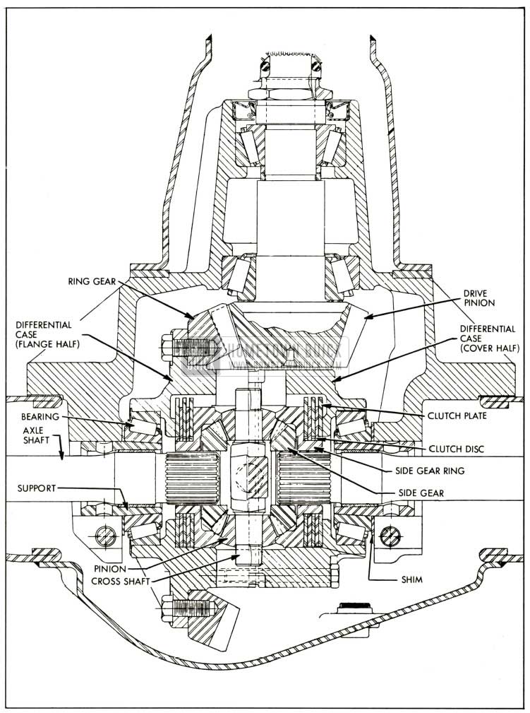
The 1959 Buick Positive Traction (non-spin) differential has pinion shafts, pinion gears and side gears which operate in a similar manner to those in a conventional differential. Behind each side gear, however, is a side gear ring and a clutch pack whose function is to hold the side gears to the case under certain driving conditions. In order to provide. room to assemble these clutches the differential case is split into two halves (the ring gear flange half and the cover half) which bolt together.
The mechanism that actuates the clutches consists of four pinion gears positioned in the case or two cross shafts which are at right angles to each other. Both ends of the shafts have bevelled surfaces which mate with ramps in the case. See figure 6-37.
1959 Buick Positive Traction Differential
The path of driving force through the differential is from the case to the cross shafts to the pinion gears to the side gears to the axle shafts. Until force is applied to the differential case by the drive pinion and ring gear, the clutches are in a relaxed or neutral position. As soon as force is applied to the case, however, the resistance to turning of the rear wheels and axle shafts forces the cross shafts to slide up the ramps in the case and, at the same time, to move sideways in opposite directions. As the cross shafts move away from each other, they carry the pinion gears with them. Shoulders on the pinion gears bear against the side gear rings to apply the clutches and hold the axle shafts to the case. Thus, both rear wheels turn at the same speed as the case and driving force cannot be lost through spinning a wheel which has poor traction. Even though one wheel is on ice, the weight of the car on this wheel causes enough resistance to turning to engage the clutches.
Each clutch pack consists of three clutch plates which are keyed to the differential case by external lugs, and two clutch discs which are splined internally to the side ring gear. The ring is splined in turn to the axle shaft. Whenever a load is applied to the differential, each side gear ring is forced outward, squeezing its clutch pack against the differential case. See figure 6-38.
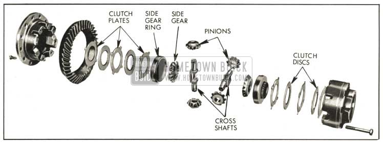
1959 Buick Positive Traction Differential-Exploded View
When turning a sharp corner under normal conditions, the differential action is essentially the same as that of a conventional differential.
CAUTION: When working on a car with a 1959 Buick Positive Traction differential, never raise one rear wheel and run the engine with the transmission in gear. The driving force to the wheel on the floor may cause the car to move.
6-15 LUBRICATION OF 1959 BUICK POSITIVE TRACTION DIFFERENTIAL
The lubricant level should be checked every 1000 miles. Maintain level at the filler plug opening by adding Special Lubricant Part No. 531536. Never use any lubricant other than this special lubricant, even for adding, or a severe clutch chatter may result when turning corners.
1959 Buick Positive Traction differentials can be easily identified either by an aluminum plate under the filler plug or by an X in a circle stamped on the bottom edge of the carrier housing flange. See figure 6-39.
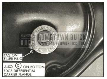
1959 Buick Identification of Positive Traction Differential Rear Axle
However, if the wrong lubricant is accidentally added, it will be necessary to completely clean out all lubricant and then fill with the special lubricant. Capacity of the rear axle housing is 6 1/2 pints.
6-16 1959 BUICK POSITIVE TRACTION DIFFERENTIAL SERVICE PROCEDURES
All rear axle service procedures are the same in a 1959 Buick Positive Traction rear axle as in a conventional rear axle, except for servicing the internal parts of the differential assembly. All rear axle parts outside of the differential such as the ring gear, differential side bearings, and axle shafts are the same in either rear axle assembly.
Disassembly of 1959 Buick Differential
- If ring gear or 1959 Buick differential case is to be replaced, remove ring gear from case. Otherwise ring gear need not be removed.
- If a differential bearing is to be replaced, pull bearing outer race from case using Remover J-6552 as described in par. 6-12 (a) of the Buick Chassis Service Manual.
- Clamp case assembly in a brass jawed vise by ring gear or by case flange.
- Mark flange half and cover half of case with a center punch to provide alignment when assembling. If cross shafts are to be reused, see that they have a paint daub on one end of each shaft matching a similar paint daub on the case to assure assembly in proper location. See figure 6-40.
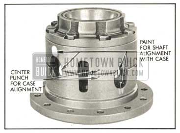
1959 Buick Alignment Marks
Cleaning and Inspection of Parts
- Make certain that all 1959 Buick differential parts are absolutely clean and dry.
- Inspect cross shafts, pinions and side gears.
Replace any parts which are excessively scored, pitted or worn.
- Inspect side gear rings and differential case halves for scoring. Replace damaged or excessively worn parts. Both halves of case must be replaced if one half is damaged or worn.
- Inspect clutch discs and plates for worn, cracked or distorted condition. If any of these defects exist, new clutch discs and plates must be installed.
Assembly of 1959 Buick Differential
- If ring gear was removed, install ring gear on case flange using three Studs J-6251 as described in par. 6-13 (e) of the Buick Chassis Service Manual.
- If a differential bearing outer race was removed, drive new race into case using Replacer J-6263.
- Place flange half of differential case on bench with opening up.
- Oil clutch plates and discs thoroughly with Special Lubricant Part No. 531536 and install clutch packs using one of the following three methods:
- If original parts are okay and clearances between both cross shafts and their ramps (as checked before disassembling) were less than .030″ and within .004″ of each other, install original clutch packs on each side gear ring starting with a clutch plate (having external lugs) and ending with a clutch plate.
- If original parts are okay but clearances between cross shafts and their ramps (as recorded before disassembling) were more than .030″ or not within .004″ of each other, adjust clearance by substituting a thicker clutch plate according to the chart in Figure 6-44.
- If original parts are defective, install new clutch packs each having a total thickness of .440″, then proceed to make a trial assembly of the differential as described below, so that cross shaft to ramp clearance can be checked.
- Oil remaining parts with Special Lubricant Part No. 531536 just before installing. With clutch packs in place on both side gear rings, next install proper side gear ring and clutch pack in flange half of differential.
- Install side gears, pinion gears, and cross shafts as shown in Figure 6-41.
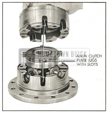
1959 Buick Installing Differential Parts
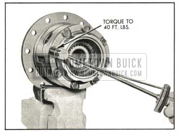
1959 Buick Torquing Differential Bolts
Checking and Adjusting Cross Shaft Clearance
To assure proper operation of the clutches, both cross shafts must be free, but must not have more than .030″ clearance between the cross shafts and their ramps.
NOTE: It is not necessary that clearances of both cross shafts be equal as long as both clearances are within .004″ of each other.
- Check each cross shaft for minimum clearance by pushing on ends of shafts with fingers. If shafts move freely, there is sufficient clearance.
- Check each cross shaft clearance by inserting two equal feeler gauges, one at each end on opposite sides of the ramp. See figure 6-43.
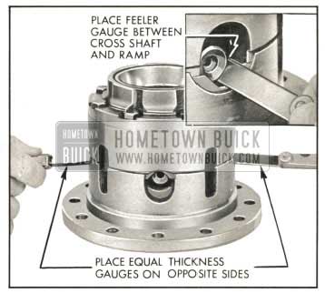
1959 Buick Checking Cross Shaft Clearance
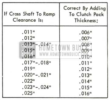
1959 Buick Cross Shaft Clearance Adjusting Chart
Clearance of the two cross shafts must be within .004″ of each other. NOTE: Clutch pack in flange half of case determines clearance at ramp in cover half; clutch pack in cover half of case determines clearance at ramp in flange half.
Clutch plates are available in four different thicknesses: .058″ to .063″, .088″ to .093″, .092″ to .097″, and .096″ to .101″. Notice that each of the four plates can vary in thickness up to .005″.
EXAMPLE: If two .019″ feeler gauges were required to take up the clearance at a cross shaft, .012″ added to the clutch pack thickness will reduce the cross shaft clearance to approximately .002″.
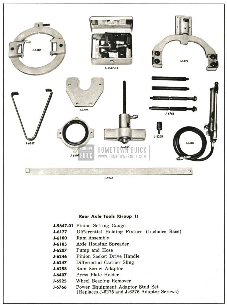
1959 Buick Rear Axle Special Tools-Group 1
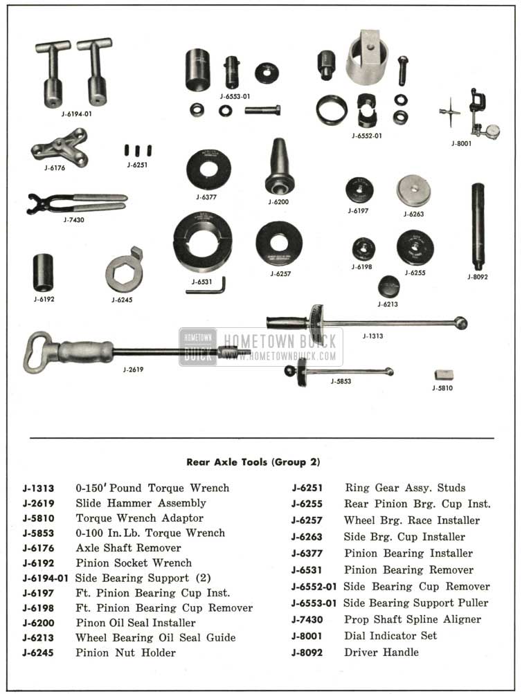
1959 Buick Rear Axle Special Tools-Group 2
Leave A Comment
You must be logged in to post a comment.