SECTION 2-G – 1959 BUICK ENGINE MOUNTING ADJUSTMENT, FLYWHEEL REPLACEMENT, ENGINE BALANCING
2-25 1959 BUICK ENGINE MOUNTING ADJUSTMENT
The 1959 Buick engine and transmission when properly aligned with the frame will rest in a normal position which does not impose any shear strain on the rubber mounting pads. During assembly, the transmission support is accurately located (with respect to the front engine mounts) both fore and aft and sideways. For this reason it is very important that the position of the support not be changed either by the removal or addition of shims to move it sideways or by moving it forward or backward. Whenever it is necessary to remove the support or loosen the support to frame bolts the support and frame should be marked at each end of the support to enable reinstallation in the same position. Also, the number and location of shims at each end of the support should be noted so they may be reinstalled in the same location. The following procedure should be used when tightening mounts to obtain proper adjustment.
1959 Buick Twin Turbine and SM Transmission Engine Mount Adjustment
- Disconnect the exhaust pipe(s) from the exhaust manifold (s). Loosen three thrust bracket to thrust pad nuts and two mounting pad to support nuts. Loosen four engine mount to frame cross member bolts.
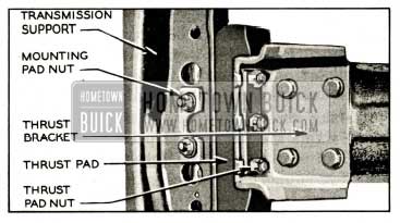
- Make sure that transmission support to frame shims are in original position and that support is in original position fore and aft. Make sure that support to frame bolts and thrust bracket to rear bearing retainer bolts are tight. See figure 2-41.
1959 Buick Synchromesh and Twin Turbine Transmission Mounting-Bottom View
- Check relationship of thrust bracket and thrust pad. If a gap exists between thrust bracket and thrust pad, engine and transmission fore and aft location is not correct and must be adjusted. If no gap exists, fore and aft position of engine and transmission assembly is correct. Tighten three thrust pad to support nuts and proceed with steps 6 through 8.
- If a gap exists between the thrust pad and thrust bracket, tighten three thrust pad to support nuts to impose a forward thrust on engine.
- Raise engine slightly and pry forward to allow front mounts to normalize.
- Tighten two mounting pad to support nuts.
- Check both 1959 Buick front engine mounts for a gap between the mount and frame. See figure 2-2. If a gap exists when the mount to frame attaching bolts are loose, the space must be filled with shims available through any Buick Warehouse under Gr. 0.027. Tighten engine mount to frame bolts.
- Reassemble the exhaust system making sure no interference exists between the pipes and other chassis members and the system is free of binds.
NOTE: When installing an engine or transmission, the 1959 Buick front engine mount to frame bolts should be the last mounting bolt to be tightened. Also, if a gap exists between the mount and the frame with the mount bolts loosened, the space must be filled with shims before the mount bolts are tightened.
1959 Buick Triple Turbine Transmission Engine Mount Adjustment
- Disconnect the exhaust pipe (s) from the exhaust manifold (s). Loosen the two outboard mount bolts on each side (mount to support weld nuts). Loosen the mount stud nuts inside the support on each side. Loosen the four engine mount to frame cross member bolts.
- Make sure that transmission support to frame shims are in original position and support is in original position fore and aft. Make sure that support to frame bolts are tight and that mount to transmission bolts and nuts are tight.
- Check relationship of thrust surfaces of mounts and transmission support. If a gap exists between thrust surfaces and support, engine and transmission fore and aft position is not correct and must be adjusted. If no gap exists, fore and aft position of 1959 Buick engine and transmission is correct. Tighten the two mount to support weld nut bolts on each side and proceed with steps 6 through 8.
- If a gap exists between the thrust surfaces of the mount and the support, tighten the two mount to support weld nut bolts on each side to impose a forward thrust on engine.
- Raise engine slightly and pry forward to allow front engine mounts to normalize.
- Tighten the mount stud nuts inside the support on each side.
- Check both front engine mounts for a gap between the mount and frame. See figure 2-2. If a gap exists when the mount to frame attaching bolts are loose the space must be filled with shims available through any Buick Warehouse under Group 0.027. Tighten 1959 Buick engine mount to frame bolts.
- Reassemble the exhaust system, making sure no interference exists between the pipes and other chassis members and the system is free of binds.
NOTE: When installing an engine or transmission the front engine mount to frame bolts should be the last to be tightened. Also, if a gap exists between the mount and the frame with the mount to frame bolts loosened, the space must be filled with shims before the mount bolts are tightened.
2-26 1959 BUICK FLYWHEEL REPLACEMENT
Replace 1959 Buick Flywheel and Check Run-out on Automatic Transmission Engine
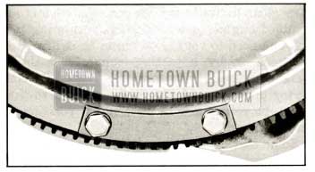
364 automatic transmission and 401 engine flywheels are not interchangeable. The 401 flywheel has greater unbalance to compensate for the greater weight of the rear throw of the crankshaft. The 401 engine flywheel can be identified by four scallops cut into the edge of the flywheel between the “1 o’clock” and the “9 o’clock” leg while the 364 automatic transmission flywheel has all three sides straight.
- Remove the transmission then remove the flywheel from the crankshaft flange.
- Inspect flywheel. If flywheel is cracked at crankshaft bolt holes, replace flywheel.
- Check for burrs around drilled holes in crankshaft flange and face of flywheel to be installed; remove any burrs with a mill file. Position flywheel so 3/8″ locating hole in flywheel bolt hole circle is matched with locating hole in crankshaft. Install bolts and tighten evenly to 50-60 ft. lbs. torque.
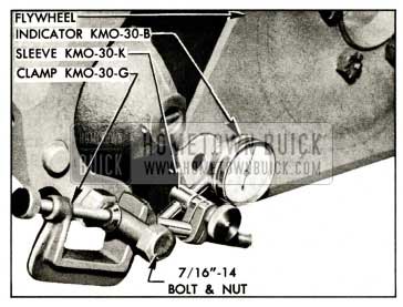
- Mount Dial Indicator KM0-30-B with Sleeve KM0-30-K and clamp KM0-30-G as shown in figure 2-42, so that stem of indicator bears against the flat surface of flywheel at inner side of the bolt holes.
1959 Buick Checking Run-Out of Automatic Transmission Flywheel
- Turn 1959 Buick flywheel, making sure that crankshaft end thrust is held in one direction, and note run-out of flywheel face. Run-out should not exceed .015″.
- If run-out exceeds .015″ attempt to correct by tapping high side of flywheel with mallet. If this does not correct run-out remove flywheel and check for burrs between flywheel and face of crankshaft flange. Remove burrs and recheck for run-out.
- If no burrs exist install a new flywheel and recheck run-out. If run-out still exceeds .015″ check run-out of rear face of crankshaft flange.
- After installation of transmission, test for engine vibration. If vibration has been introduced by installation of new flywheel make correction as described in paragraph 2-27.
Replace 1959 Buick Flywheel or Ring on Synchromesh Engine
- Remove 1959 Buick transmission and clutch assembly, being sure to mark clutch cover and flywheel so that the assembly can be reinstalled in its original position.
- Remove flywheel, which is located in a definite position on the crankshaft flange by means of one dowel.
- If the flywheel ring is to be replaced, drill a 5/16″ hole in the ring between two teeth and split the ring at this point with a cold chisel. Heat and shrink the new ring in place as follows:
- Polish several spots on the ring with emery cloth.
- Use a hot plate or a slowly moving torch to uniformly heat the ring until the polished spots turn blue (approximately 600° F.).
CAUTION: Heating the ring in excess of 800 deg. F. will destroy the heat treatment given during manufacture. - Quickly place ring in position against shoulder on flywheel, with beveled end of teeth away from shoulder, then allow ring to cool slowly until it is tight in place.
- Make certain that the flywheel and the crankshaft flange are clean and free of burrs that would cause run-out, then install flywheel.
- After installation of clutch and transmission test 1959 Buick engine for vibration. If engine has vibration that did not exist before installation of new parts, make correction as described in paragraph 2-27.
Correction of Misaligned Automatic Transmission Flywheel
The three legs of automatic transmission flywheels should all bear equally against the converter pump cover. Before attempting to balance a 1959 Buick engine transmission assembly the following procedure should be observed:
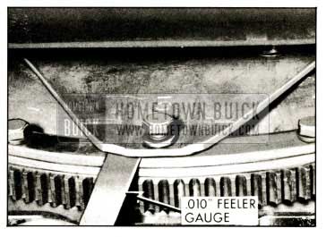
- Loosen one flywheel attaching bolt and check contact between flywheel leg and converter pump cover. A .010″ feeler gauge should slip between flywheel and cover with slight drag. See Figure 2-43.
1959 Buick Checking Contact Between Pump Cover and Flywheel
- If flywheel bears heavily against converter pump cover, pry it away until light contact to .010″ clearance exists.
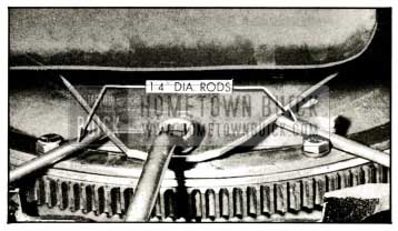
- If more than .010″ clearance exists between flywheel and pump cover insert two 1/4″ diameter rods between cover and flywheel as shown in Figure 2-44, tighten attaching bolt to bend flywheel into correct contact with pump cover. Remove rods and check results.
1959 Buick Bending Flywheel Leg Toward Pump Cover
- Repeat check on each leg of flywheel and make corrections as necessary to insure equal contact of each flywheel leg with pump cover.
2-27 CORRECTION OF UNBALANCED 1959 BUICK ENGINE OR MISALIGNED FLYWHEEL
Individual 1959 Buick crankshafts, flywheels, and other rotating parts are dynamically balanced to very close limits in production. Completely assembled 1959 Buick engines are also given a running test and balanced to very close limits by drilling the flywheel or by adjusting converter balance weights as required. For this reason, a converter pump should always be marked so that it can be reinstalled in its original position on the flywheel.
Some cases of excessive vibration may result from replacement of rotating parts. An extremely unbalanced condition should always be corrected by replacing parts which are abnormally out of balance or materially different in weight from corresponding parts. The following procedures are intended only for correction of minor cases of unbalance which may occur when individually balanced parts are replaced.
Critical Speed of Vibration
Determine the 1959 Buick engine speed at which the vibration is most pronounced, so that test at this critical speed may be made after corrective work is done.
- Place car solidly on stands high enough to permit working underneath.
- Connect a tachometer to engine. Start engine and with transmission control lever in Parking position increase speed gradually until a point is reached where the objectionable vibration is definite. Note engine RPM at this critical speed, then stop 1959 Buick engine.
Correction of Unbalanced Automatic Transmission Engine
- Remove bell housing cover.
- Install one balance weight No. 1178109 (.060″ thick) under the head of two converter pump cover bolts, and tighten bolts to 25-30 ft. lbs. torque.
NOTE: Do not place a weight at a flywheel to converter driving bolt because these bolts are not long enough for addition of weights.
- Run 1959 Buick engine at critical speed and carefully compare vibration with that obtained without the weight, then stop engine.
- Mark location of balance weight on converter pump, remove weight and tighten bolt to 25-30 ft. lbs. torque.
- Install the balance weight at other converter pump cover bolts and compare the vibration produced at critical speed.
1959 Buick Installation of Balance Weight
- At the point where the balance weight produced the greatest improvement in vibration install weights of proper thickness to eliminate objectionable vibration. Balance weights are available under Group 4.115 in several different thicknesses.
NOTE: When factory balancing of converter pump is changed to balance an engine, the pump cannot be used with any other engine.
- Install bell housing cover. Remove tachometer and car stands.
Correction of Unbalanced Synchromesh Engine
If the vibration developed after removal and installation of clutch assembly, check all clutch cover bolts to make sure they are of same length and that each has one lock washer. Also check . marks that were made when clutch was removed and disassembled to make sure that clutch was assembled and installed according to these marks. Make any corrections indicated by this inspection and run 1959 Buick engine at the critical speed to check results.
If 1959 Buick clutch assembly and installation does not appear to be at fault, mark clutch cover and flywheel and remove clutch assembly. Run 1959 Buick engine at critical speed and check for vibration. If vibration is eliminated, the clutch is at fault and should be balanced as described below. If vibration still exists, however, it will be necessary to balance the flywheel on the crankshaft.
To balance the 1959 Buick flywheel, insert one clutch cover bolt successively in each hole in flywheel and check results at each position by running the engine. It may be necessary to vary the test weight by adding washers or by using a shorter bolt. When a proper weight and position has been found to eliminate the vibration, the bolt will be on the light side of flywheel. Remove the bolt and drill shallow holes in diametrically opposite side of flywheel, until enough weight has been removed to make engine run smooth. Use a 3/8″ drill and do not drill any hole more than 1/4″ deep.
After making sure that 1959 Buick engine runs smooth with clutch removed, install clutch assembly according to marks made before removal and again check for vibration at the critical speed. If vibration exists with clutch installed, install one plain washer under the lock washer of each clutch cover bolt in turn until a location is found where the engine runs smooth. It may be necessary to place plain washers on two adjacent bolts in order to obtain enough weight at the proper location to secure balance.
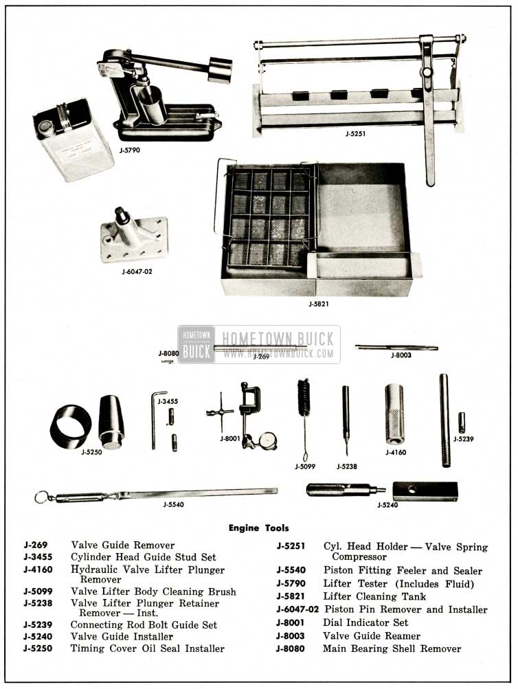
1959 Buick Engine Special Tools
Leave A Comment
You must be logged in to post a comment.