SECTION 7-C – 1959 BUICK CHASSIS SUSPENSION SERVICE, ADJUSTMENT, AND REPLACEMENT PROCEDURES
7-8 1959 BUICK TIRE SERVICE AND INSPECTION
1959 Buick Tire Inflation and Inspection
Maintenance of correct inflation pressure in all 1959 Buick tires is one of the most important elements of tire care. Correct tire pressure is also of great importance to ease of handling and riding comfort. Overinflation is detrimental to tire life but not so much as underinflation. Inflate all tires according to tire temperature as specified in paragraph 1-1.
Driving without valve caps contributes to underinflated tires. The valve cap keeps dirt and water out of the valve core and seals the valve against leakage. Whenever tires are inflated be sure to install valve caps and tighten firmly by hand. Make sure that rubber washer in cap is not damaged or missing.
If 1959 Buick tires are checked at frequent intervals and adjusted to correct inflation pressure, it is often possible to detect punctures and make a correction before a tire goes flat, which may severely damage tire if car is in motion. Slight differences in pressure between tires will always be found, but a tire that is found to be 3 or more pounds below the lowest of its running mates can be suspected of having a leaking valve or a puncture.
All 1959 Buick tires should be inspected regularly to avoid abnormal deterioration from preventable causes. If tires show abnormal or uneven wear the cause should be determined and correction should be made.
See that no metal or other foreign material is embedded in the tread. Any such material should be removed to prevent damage to tread and tire carcass. Cuts in a tire which are deep enough to expose the cords will allow dirt and moisture to work into the carcass and ruin the tire unless promptly repaired.
1959 Buick Tubeless Tire Repairs
A leak in a 1959 Buick tubeless tire may be located by inflating the tire to recommended pressure (par. 1-1) and then submerging tire and wheel assembly in water, or by applying water to tire with a hose if wheel is mounted on car. Remove water from area where air bubbles show and mark the area with crayon. After removal of the puncturing object from tire, the puncture must be sealed to prevent entrance of dirt and water which would cause damage to the tire carcass.
A small puncture of less than 3/32″ diameter may be sealed without removal of tire from wheel by injecting sealing dough with a gun. Punctures up to 1/4″ diameter may be sealed by installation of a rubber plug with cement, after tire has been removed from wheel. Sealing dough with gun, and rubber plugs with cement are contained in tire repair kits available through tire dealers. These materials should be used as directed in the instructions supplied with the kits. If a puncture is larger than 1/4″ or there is other damage to the tire carcass, repairs should be made by authorized tire dealers in accordance with instructions of the tire manufacturer.
1959 Buick Wheel Leaks
- Examine rim flanges for sharp dents. Any dent visible to the eye should be straightened. The 1959 Buick rim flanges should be thoroughly cleaned with No. 3 coarse steel wool thereby removing all oxidized rubber, soap solution, etc. If the
- Wipe old grease out of hub and from steering knuckle spindle. Clean and inspect all bearing parts as described under Bearing Service (par. 1-9), and replace any that are faulty.
- If a bearing cup has to be replaced, drive the old cup out with a punch. Use care when installing the new cup to start it squarely into hub, to avoid distortion and possible cracking.
- When inspecting or replacing bearing cones (inner races) make sure that cones are free to creep on spindle of steering knuckle. The cones are designed to creep on the spindle in order to afford a constantly changing load contact between the cones and the ball bearings. Polishing the spindle and applying bearing lubricant will permit creeping and prevent rust forming between cone and spindle.
- Wash and thoroughly dry all bearing parts, because wheel bearing lubricant will not adhere to oily surfaces.
- Thoroughly pack both ball bearing assemblies with new wheel bearing lubricant, preferably using a bearing packer. If packer is not available, work lubricant into bearings by hand. In either case, remove any surplus lubricant.
- Apply a light coating of lubricant to spindle and inside surface of wheel hub to prevent rusting.
- Place inner bearing assembly in cup and install a new oil seal, driving seal squarely into hub with installer J-6541. Carefully install inner bearing cone in oil seal. NOTE: Never place cone on spindle because seal will be damaged as wheel is installed.
- Install 1959 Buick wheel on spindle, then install outer bearing assembly, cone, safety washer and nut. See figure 7-8.
1959 Buick Front Wheel Hub and Bearings
- Adjust bearings as follows (subpar. b).
Adjustment of 1959 Buick Front Wheel Bearings
- Tighten spindle nut to 30 ft. lbs. torque and rotate hub to seat bearings.
- Back off spindle nut and re-torque to 12.5 foot pounds.
- If either cotter pin hole aligns with a slot in the nut, insert cotter pin. Otherwise back off nut till nearest hole and slot line up and insert cotter pin.
- Before installation of grease cap in hub, make sure that end of spindle and inside of cap are free of grease so the radio static collector makes good contact. Make sure that static collector is properly shaped to provide good contact between end of spindle and the grease cap.
7-11 REMOVAL AND INSTALLATION OF 1959 BUICK BALL JOINTS AND/OR STEERING KNUCKLE
Removal and Replacement of 1959 Buick Upper Ball Joint
- Raise 1959 Buick with jack under frame. (On jobs equipped with air ride, also close air ride shut off valve and support car at frame in rear and at frame front on side opposite that being worked on.) Remove wheel and tire.
- Remove cotter pin from castellated nut on upper ball joint tapered stud.
- Loosen, but do not remove nut. Force of 1959 Buick chassis spring will be tending to disengage ball joint tapered stud from steering knuckle. Rap knuckle sharply in area of tapered stud to disengage stud from knuckle.
- Support 1959 Buick weight under outer edge of spring seat and remove nut from ball joint tapered stud.
- Support car weight on frame and lower spring seat to lower knuckle, hub and drum assembly slightly. Be careful to avoid damage to brake hose.
- Raise upper control arm and remove rubber bumper under upper control arm.
- Center punch the four 5/16″ rivets as close to the center as possible. Drill a 1/8″ hole through center of rivets.
- Drill a 1/8″ hole more than half-way but not all the way through each rivet.
- Use a 1/2″ drill or chisel to remove the rivet heads.
- Use a 1/4″ punch and hammer to drive rivets out.
- Assemble new ball joint to upper control arm with 5/16″ bolts inserted from bottom. (Nuts and lockwashers on top) Torque nuts to 15-20 ft. pounds.
- Reinstall rubber bumper.
- Turn tapered stud so cotter pin hole is fore and aft and assemble rubber dust shield over stud. Move knuckle up by jacking under outer edge of spring seat.
- Wipe tapered hole in knuckle and tapered stud clean and assemble stud to knuckle with castellated nut. Torque to 30-40 ft. pounds and install cotter pin. (On jobs equipped with air ride, open air ride shut off valve.)
- Reinstall wheel and tire and remove frame support.
Removal and Replacement of 1959 Buick Lower Ball Joint
- Raise car, remove wheel and tire. (On jobs equipped with air ride, also close air ride shut off valve and provide frame support at all four corners of car.)
- Disconnect stabilizer link (if so equipped).
- Remove 1959 Buick shock absorber (Par. 7-15).
- Remove cotter pin and loosen nut on lower ball joint tapered stud.
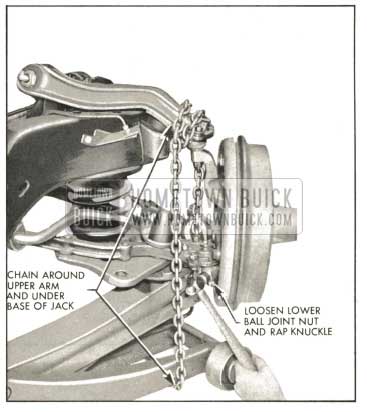
- With car supported by frame, place jack under outer edge of spring seat. Wrap chain around upper control arm and under base of jack, fasten chain securely. See Fig. 7-9. Raise jack to place tension on lower ball joint stud.
1959 Buick Separating Lower Ball Joint and Steering Knuckle
- Rap 1959 Buick steering knuckle in area of stud to separate stud from knuckle. Lower jack slightly; remove nut and chain. NOTE: Interference may exist between nut and backing plate. After partially removed, raise jack slightly or move knuckle in relation to lower control arm to provide clearance. Raise jack; separate stud from knuckle. Lift knuckle, hub, and drum assembly and support in raised position by placing suitable prop between upper control arm and frame.
- Lower jack carefully. Remove 1959 Buick chassis spring.
- With outer end of lower control arm resting on floor and car supported in safe manner, center punch the four lower ball joint rivets and drill a 1/8″ hole through center of each rivet. Drill a 5/16″ hole more than half-way but not all the way through each rivet. Remove rivet heads with chisel or 1/2″ drill. Use 5/16″ punch to drive the rivets out.
- Install a new ball joint using 3/8″ bolts in package; longer bolts at inner location. Assemble bolts head down. (Nuts and lock washers on top.) Torque to 35-40 ft. lbs.
- Tape rubber cushion to top of spring. (On power steering only jobs, a 1/8″ steel shim is used at top of left spring also. On power steering and air conditioned jobs, no shim is used either side unless they have been added to correct trim height.)
- Position 1959 Buick spring correctly in frame cross member and raise lower control arm to contact spring. Rotate spring if necessary to locate end of spring in drain hole of spring seat. Wire or otherwise suitably retain spring in spring seat. Raise lower control arm with jack placed under outer edge of spring seat. Remove prop under upper control arm; lower knuckle.
- Wipe stud and hole in knuckle clean; assemble rubber dust shield on stud and start stud into knuckle hole. Before inserting stud completely turn cotter pin hole fore and aft and start nut on stud. Tighten castellated nut securely and install cotter pin.
- Reassemble grommets, retainers, and nut on stabilizer link (if so equipped).
- Reinstall 1959 Buick shock absorber (Par. 7-15).
- Reinstall wheel and tire and remove frame support.
- Open air ride shut off valve if car is so equipped.
Removal and Replacement of 1959 Buick Steering Knuckle
- Follow steps 1-2 and 3 of sub paragraph (a) above and heavily lubricate tapered stud of upper ball joint.
- Disengage lower stud using procedure outlined in steps 1 through 7 of sub paragraph (b) above.
- With weight of knuckle hub and drum assembly tending to disengage knuckle from upper stud, rap knuckle in stud area to separate. Do not remove nut.
- Remove dust cap, spindle nut and safety washer. Slide drum and hub assembly and outer bearing off spindle.
- Remove inner wheel bearing and bearing cone.
- Remove cotter pin and nuts from two lower bolts. (Backing plate to steering knuckle and steering arm). Remove nuts and lock washers from two upper bolts. Remove all four bolts.
- Slide backing plate assembly off knuckle. Support out of the way to avoid damage to brake hose and prevent grease or dirt getting on brake lining.
- Remove upper ball joint nut and steering knuckle.
- To replace knuckle, wipe stud of upper ball joint clean, assemble to knuckle with cotter pin hole fore and aft, torque nut to 30-40 ft. lbs. and install cotter pin.
- Wipe lower ball joint stud clean and assemble to knuckle as outlined in steps 10 through 16 of sub paragraph (b) above.
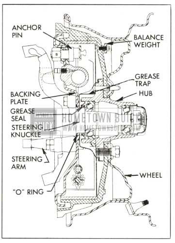
- Assemble new “O” ring seal on steering knuckle spindle and slide backing plate assembly into position.
- Install two backing plate to steering knuckle and steering arm bolts with longer bolt at rear location. Torque nuts to 90-100 ft. lbs. and install cotter pins. Install two backing plate to knuckle bolts, nuts and lock washers. Torque nuts to 65-75 ft. lbs.
- Examine grease seal in hub, replace if necessary, using installer J-6541.
- Wipe spindle clean and slide on inner bearing cone. Make certain inner bearing has sufficient bearing grease and position in the cone. Slide drum and hub assembly into position carefully to avoid damage to grease seal or bearing.
- Assemble outer bearing cone, safety washer and nut on spindle. Adjust bearing preload as outlined in paragraph 7-10, sub paragraph (b).
- Reinstall wheel and tire and remove frame support.
7-12 REMOVAL AND INSTALLATION OF 1959 BUICK UPPER CONTROL ARM SHAFT OR ARM, SHAFT AND BALL JOINT ASSEMBLY
NOTE: Upper control arm shafts, bushings and ball joints are available separately. However, upper control arms are available only as an assembly (arm, shaft, bushings and ball joint).
- Separate upper ball joint from knuckle according to steps 1 through 5 of Par. 7-11, sub par a.
- Remove shaft to frame bracket nuts, carefully noting number, location and thickness of adjusting shims between shaft and frame bracket. Remove arm assembly.
NOTE: If work is being performed on right side it will be necessary to remove generator.
- If shafts and bushings only are being replaced, clamp arm assembly in vise and remove old bushings and shaft.
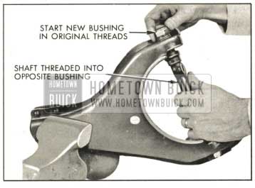
- Assemble new grease seals on shaft and position shaft in arm. Start new bushing in original threads of arm and thread shaft into bushing to aid in alignment. Torque bushing to 70-75 ft. lbs. torque.
- Start second bushing into original threads of arm with shaft threaded into opposite bushing. See Fig. 7-10.
1959 Buick Upper Control Ann Bushing Replacement
- After bushing has been threaded part way into arm, rotate shaft to engage threads of second bushing as an aid in piloting the bushing squarely into position.
- Torque bushing to 70-75 ft. lbs. Shaft should be free enough to turn by hand. Install grease fittings and lubricate bushings.
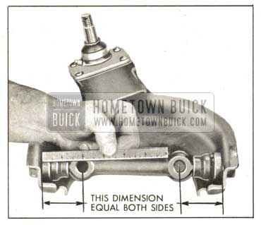
- Rotate shaft to make distance between shaft bolt holes and arm equal both sides as nearly as possible. See Figure 7-11.
1959 Buick Upper Control Arm Shaft Position
- Install arm assembly by reversing removal procedure, being careful to locate the steel washers under the heads of the shaft to frame bracket bolts. Pay particular attention to number, location and thickness of adjusting shims between shaft and frame bracket. Torque shaft to frame bracket bolts to 90-100 ft. lbs.
- When reassembling upper ball joint to knuckle, follow instructions outlined in Par. 7-11 sub par a, steps 13-14-15.
- Check and adjust front end alignment as necessary.
7-13 CHECKING AND REPLACING 1959 BUICK CHASSIS SPRINGS
Checking 1959 Buick Spring Trim Dimensions
Optional equipment, undercoating, accumulated dirt, etc., changes the car weight and must be considered when checking 1959 Buick spring trim dimensions. Because of the many possible variations in loading due to optional equipment it is not possible to give dimensions for all; therefore, the spring trim dimensions given below are for the standard car only, without optional equipment or undercoating and with car at curb weight. Curb weight includes gas, oil, water, and spare tire but no passengers.
Before measuring 1959 Buick spring trim dimensions, bounce both ends of car up and down several times to make sure there is no bind in suspension members, and to let springs take a natural position. When car is at rest, measure the trim height at point “Y” for front spring or point “Z” for rear spring, as indicated in figure 7-12.
- 1959 Buick Front Springs. On a car having service miles the front spring trim dimension “Y” should be as shown in Figure 7-12 chart.
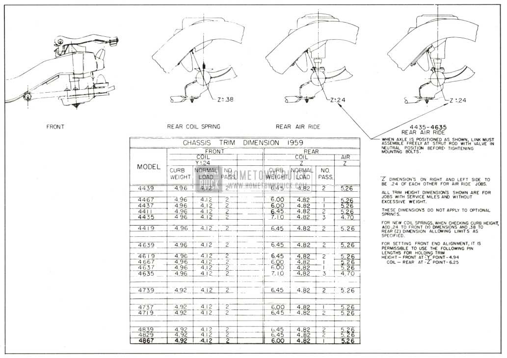
1959 Buick Trim Height Chart
NOTE : When checking NEW car add 1/4″
When the 1959 Buick front spring trim dimension is found to be too low, correction may be made by installing special shims (Group 7.425), 1/8″ thick, between upper end of spring and the frame. If more than three shims are required, replace the spring.
- 1959 Buick Rear Springs. On a car having service miles the rear spring trim dimension should be as shown on Figure 7-12 chart.
NOTE : When checking NEW car add 3/8″
If 1959 Buick rear spring trim dimension is less than specified or additional height is required to prevent excessive “bottoming” in exceptional cases, install additional spring insulators (group 7.545), divided between upper and lower ends of spring. If more than three additional insulators are required replace the spring. Installation of new springs should not increase spring trim dimension “A” more than 1″ over specified maximum limit.
Removal and Installation of 1959 Buick Front Spring
- Raise car; remove wheel and tire. On jobs equipped with air ride, close air ride shut off valve and provide frame support at all four corners of car.
- Disconnect stabilizer link (if so equipped).
- Remove shock absorber (Par. 7-15).
- Remove cotter pin and loosen nut on lower ball joint tapered stud.
- With car supported by frame place jack under outer edge of spring seat. Wrap chain around upper control arm and under base of jack, fasten chain securely. See Fig. 7-9. Raise jack to place tension on lower ball joint stud.
- Rap steering knuckle in area of stud to separate stud from knuckle. Lower jack slightly; remove nut and chain. NOTE: Interference may exist between nut and backing plate. After partially removed, raise jack slightly or move knuckle in relation to lower control arm to provide clearance. Raise jack; separate stud from knuckle. Lift knuckle, hub, and drum assembly and support in raised position by placing suitable prop between upper control arm and frame.
- Lower jack carefully. Remove 1959 Buick chassis spring.
- Tape rubber cushion to top of spring. (On power steering only jobs, a 1/8″ steel shim is used at top of left spring also. On power steering and air conditioned jobs, no shim is used either side unless they have been added to correct trim height.)
- Position spring correctly in frame cross member and raise lower control arm to contact spring. Rotate spring if necessary to locate end of spring in drain hole of spring seat. Wire or otherwise suitably retain spring in spring seat. Raise lower control arm with jack placed under outer edge of spring seat. Remove prop under upper control arm; lower knuckle.
- Wipe stud and hole in knuckle clean; assemble rubber dust shield on stud and start stud into knuckle hole. Before inserting stud completely turn cotter pin hole fore and aft and start nut on stud. Tighten castellated nut securely and install cotter pin.
- Reassemble grommets, retainers, and nut on stabilizer link (if so equipped).
- Reinstall 1959 Buick shock absorber (Par. 7-15).
- Reinstall wheel and tire and remove frame support.
- Open air ride shut off valve if car is so equipped.
Removal and Installation of 1959 Buick Rear Spring
- Raise car and support frame.
- Disconnect both 1959 Buick rear shock absorbers at lower end. Disconnect height control valve links. CAUTION: Air ride jobs must not have the frame raised above the axle further than position limited by shock absorber travel without disconnecting height control valve links or damage to the height control valves will result.
- Remove upper and lower spring clamps. Remove spring. On jobs equipped with Air Ride, remove plunger bearing plate to axle housing bracket bolts and remove plunger assembly by sliding off axle bracket. Disconnect air supply flared tube nut; remove bracket and screw at lower edge outboard side of spring and bolt through welded bracket at upper inboard side of spring. Remove spring.
- When replacing coil spring, check number stamped on one end coil to be sure spring is correct for the car model as specified in Group 7.503 of the Master Parts List.
- On coil spring jobs, be sure spring insulator at upper location is in good condition; then attach upper end of spring using spring clamp, bolt insulator, fiat washer, lockwasher and nut in order named. Attach lower end of spring to axle housing bracket with spring clamp, lockwasher and nut. (On jobs equipped with Air Ride, be certain a new sealing ring is properly seated in air supply connector; then position spring assembly in frame member and install clamp and bolt at lower outboard edge of spring and bolt through bracket at top inboard location. Connect air line flared tube nut and tighten to 5-10 inch pounds torque. Position plunger assembly in diaphragm and install two bearing plate to axle housing bracket bolts.
- On coil spring jobs, lower car and attach shock absorbers with normal car weight on rear wheels to clamp rubber bushings in a neutral position. (On jobs equipped with Air Ride, reattach shock absorber lower ends and tighten bolts hand tight. Reconnect height control valve links. Start engine, when lift is accomplished, remove frame support. When car reaches normal trim, torque lower shock mounting bolts to 60-80 ft. lbs. torque).
Use of Special Overload Rear Coil Springs
Special 500 pound overload rear coil springs are available for service installation in cases where heavy loads are carried or heavy trailers are towed. Overloading any series rear axle in excess of 500 pounds is not recommended.
In estimating rear spring overloads, place rear wheels of car on scale, with car at curb weight and “no load in rear compartment other than spare wheel and tire. After obtaining weight, hook trailer to car, or place desired load in rear compartment, and read scale again. The additional weight is the amount of overload on springs and rear axle.
Trailer design, and distance that trailer coupling is located to rear of rear axle center line, are the major factors governing effective trailer overload. Instructions for attaching trailers to Buick cars may be obtained from Buick Motor Division Factory Service Department.
1959 Buicks equipped with Air Ride will automatically compensate for loads on the rear wheels up to 500 pounds in excess of normal. These cars should never be loaded beyond this point however, as serious damage to Air Ride components will result.
7-14 REPLACE OR 1959 BUICK REBUSH LOWER CONTROL ARM ASSEMBLY
If a lower control arm is bent or broken it should be replaced with a :new assembly which includes the ball joint, shaft, bushings, and dirt seals. The riveted parts of the assembly are not furnished separately. If only the shaft and bushings or ball joint require replacement they can be obtained separately.
Use all of the following steps for replacement of control arm shaft and bushings. Use only steps 1, 9 and 10 for replacement of control arm and shaft assembly.
- Remove front 1959 Buick chassis spring (par. 7-13) then remove lower control arm assembly from frame front cross member.
- Unscrew bushings and remove shaft from control arm.
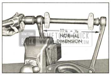
- Check the distance between inner ends of control arm. The normal dimension is 11 1/4″ plus or minus 1/32″, from inside to inside. See figure 7-14.
1959 Buick Installing First Bushing
- Install a rubber seal over each threaded end of new control arm shaft.
- Insert one end of shaft with the seal in place in one control arm end and force opposite end’ of shaft into the other control arm end. A piece of wood approximately 1 1/4″x2 1/2″x24″ long can be used as a pry. See figure 7-13.
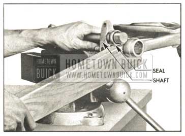
1959 Buick Springing Arm Over End of Shaft
- Fasten control arm securely in vise close to one end to prevent springing or distortion.
NOTE: Apply a liberal amount of white lead or Lubriplate to both bushings before installing in arms.
- Start first bushing on shaft and into control arm at the same time. Turn bushing until head is tight against arm and tighten to a minimum of 150ft. lbs. torque. See figure 7-14.
- Center the shaft between the arms and install the second bushing as in Step 7, turning shaft as required to thread into the bushing so that no binding exists.
After bushings are installed shaft must be free enough to turn by hand.
- Before installing lower control arm and shaft assembly, turn shaft to locate the bolt holes at both ends so they are equally distant from the inside surface of the arms, then bolt shaft to frame front cross member If installing new control arm assembly, leave shaft in position determined by locating wire.
- Install front chassis spring (par. 7-13). Install grease fittings and lube bushings. Check caster, camber, and toe-in. Adjust as necessary (par. 7-17).
7-15 1959 BUICK SHOCK ABSORBER SERVICE AND REPLACEMENT
Checking 1959 Buick Shock Absorbers
Both 1959 Buick front and rear shock absorbers are filled and sealed in production and cannot be refilled in service.
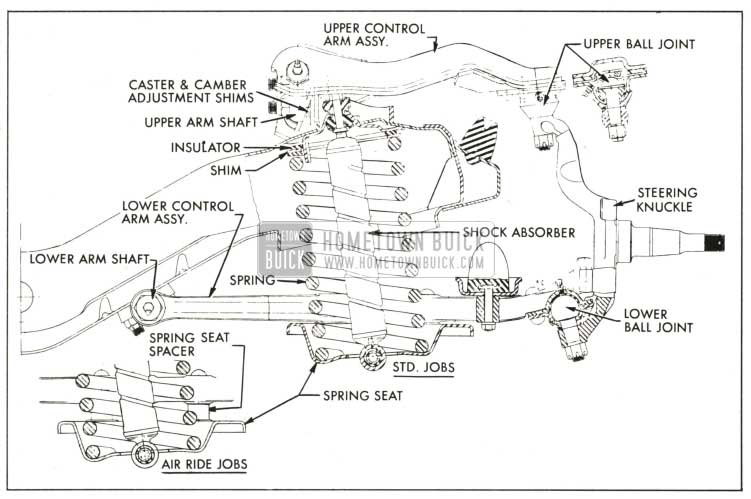
1959 Buick Front Spring and Shock Absorber Installation
Removal and Installation of 1959 Buick Front Shock Absorber
- Raise front of car.
- Remove upper mounting stem nut, grommet retainer and grommet. A 1/4″ flat on shock stem may be used to hold stem while removing nut.
- Remove two lower mounting bracket to spring seat bolts. Lower shock through spring seat.
- Make certain that 1959 Buick shock absorber being installed is correct for car model as indicated by part number stamped on outer tube. See Master Parts list group 7.345.
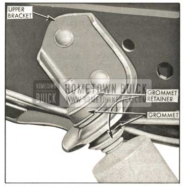
1959 Buick Rear Shock Absorber Upper Mounting
- Assemble lower grommet retainer and grommet (small end up) on shock stem. Extend shock and install through spring seat.
- Install two shock bracket to spring seat bolts and lockwashers.
- Assemble top grommet (small end down), grommet retainer, and nut on stem. Tighten nut to 5-10 foot pounds.
Removal and Installation of 1959 Buick Rear Shock Absorber
- Raise rear of car. (On air ride jobs the height control valve links must be disconnected).
- Remove lower shock absorber mounting eye bolt, nut, washer, spacer and rubber bushings.
- Remove upper shock absorber mounting stem nut, upper grommet retainer and grommet. Remove shock absorber.
- Inspect all rubber bushings and grommets and replace if not in good condition. If shock absorber operation is faulty, it must be replaced as it cannot be repaired. CAUTION: Rear shock absorbers on jobs equipped with Air Ride have an extended length which is approximately one inch shorter than standard shock absorbers. Standard 1959 Buick shock absorbers should never be used on Air Ride jobs as serious damage to air springs or height control valves may result.
- Make certain that new shock absorber is correct for car model as indicated by part number stamped on the outer tube. See Master Parts List Group 7.345 for standard and optional parts.
- Assemble grommet retainer and grommet (small end up) on upper stem of shock absorber. Insert stem through bracket hole and assemble grommet (small end down) grommet retainer and nut. Torque nut to 5 to 10 ft. lbs. Place spacer and rubber bushings in place in lower shock absorber eye. Install pivot bolt with head toward rear and flat washer and nut toward front.
- Lower rear end of car. Then tighten pivot bolts to 60-80 ft. pounds torque.
NOTE: Car weight must be on rear wheels when tightening shock absorber lower ends to clamp rubber bushings in a neutral position.
1959 Buick shock absorber calibrations as furnished in production have been carefully engineered to provide the best ride control over a wide range of driving conditions. Substitution of other calibrations should not be attempted under any circumstances, unless authorized by the Buick Motor Division.
7-16 1959 BUICK TRACK BAR SERVICE AND REPLACEMENT
Removal of 1959 Buick Track Bar Assembly
- Raise car and support axle housing so weight of car will be on rear springs.
- Right end: Remove three track bar support to frame bracket bolts and remove track bar pivot bolt. Remove support.
- Left end: Remove track bar pivot bolt.
- Lift end of track bar up out of axle bracket to remove bar.
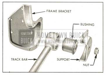
1959 Buick Track Bar, Bushing and Frame Bracket-Exploded View
Inspection of 1959 Buick Track Bar Assembly
- 1959 Buick track bar must not be “bowed” more than 1/8″ in any direction.
- If straightening is necessary, it must be accomplished without heating the bar.
- Check rubber bushings for evidence of deterioration, tears, etc. Examine center steel sleeve for excessive wear or separation from rubber.
Removal and Replacement of 1959 Buick Track Bar Bushings
- Press out old bushing from side which has no flange using a ram 2 1/4″ O.D. Considerable force will be required to remove the bushing.
- Install new bushing in track bar eye by pressing on flanged side of bushing. Press in bushing until flange is in contact with eye of track bar.
Installation of 1959 Buick Track Bar
NOTE: Track bar to bracket bolts must not be tightened unless car is at normal trim height.
- Slip left end of track bar into axle bracket. Install but do not tighten bolt.
- Position track bar against frame bracket and assemble three support bolts and track bar pivot bolt loosely. Tighten track bar pivot bolt to 90-105 foot pounds torque. Tighten support bolts to 15-25 foot pounds torque.
- Tighten axle end track bar pivot bolt to 90-105 foot pounds torque.
7-17 1959 BUICK FRONT WHEEL ALIGNMENT
1959 Buick wheel alignment is the mechanics of properly adjusting all the factors affecting the position of front wheels so as to cause the car to steer with the least effort and to reduce tire wear to a minimum.
Correct alignment of the frame is essential to proper alignment of front and rear wheels. Briefly, the essentials are that the frame must be square in plan view within specified limits, that the top and bottom surfaces of front cross member must be parallel fore and aft, and the bolt holes for support upper arms and lower control arm shafts must be of correct size and location. Checking frame alignment is covered in Group 12.
It should also be understood that wheel and tire balance has an important effect on steering and tire wear. If wheels and tires are out of balance, “shimmy” or “tramp” may develop or tires may wear unevenly, and give the erroneous impression that the wheels are not in proper alignment. For this reason, the wheel and tire assemblies should be known to be in proper balance before assuming that wheels are out of alignment.
Close limits on caster, front wheel camber, and theoretical king pin inclination are beneficial to car handling, but require only reasonable accuracy to provide normal tire life. With the type of front suspension used, the toe-in adjustment is much more important than caster and camber in so far as tire wear is concerned. Caster and camber adjustments need not be considered unless visual inspection shows these settings to be out, or unless the car gives poor handling on the road.
In the majority of cases, services consisting of inflating tires to specified pressure and interchanging tires at recommended intervals (par. 7-8), balancing all wheels and tires (par. 7-16) adjusting steering gear (par. 8-4), and setting toe-in correctly (subpar. e, below) will provide more improvement in car handling and tire wear than will front end alignment adjustments as usually made on front end alignment equipment.
The use of accurate front end alignment is essential to determine whether front suspension parts have been damaged by shock or accident, and to obtain correct alignment settings after new parts have been installed.
Inspection Before Checking 1959 Buick Front Wheel Alignment
Before any attempt is made to check or make any adjustment affecting caster, camber, toe-in, theoretical king pin inclination, or steering geometry, the following checks and inspections must be made to insure correctness of alignment equipment readings and alignment adjustments.
- The 1959 Buick front tires should have approximately the same wear and all tires must be inflated to specified pressures (par. 1-1).
- Check front wheel bearings for looseness and adjust, if necessary (par. 7-10).
- Check for run-out of wheels and tires and correct to within limit of 1/8″ run-out at side of tires, if necessary.
- Check 1959 Buick wheels and tires for balance and correct if out of balance (par. 7-8).
- Check for looseness at ball joints and tie rod ends; if found excessive it must be corrected before alignment readings will have any value (par. 7-5).
- Check 1959 Buick shock absorber action and correct, if necessary (par. 7-5).
- Check trim height, if out of limits, correct with shims or replace spring. CAUTION: Consideration must be given the optional equipment on the car undercoating , dirt, etc.
Good judgment should be exercised before replacing a spring when car trim height is only slightly out of limits. Spring replacement under conditions of excessive weight as mentioned above will accomplish little and must be accompanied by shimming to obtain satisfactory results. 1/8″ shims are available through Buick Parts warehouses under Group 7.425. Refer to Paragraph 7-13.
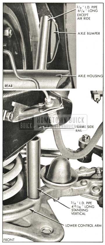
- Car must be on level surface. Place a piece of 3/4″ I.D. pipe 4 15/16″ long between frame and lower control arm at each front wheel as shown in figure 7-18. Position the pipe over the front outer spring seat rivet and make sure it is standing vertical. Use sand bags or other suitable weights when necessary to hold car down on pipes.
1959 Buick Alignment Pins in Place
- Bring the rear of the car to proper height. If the gas tank is full and the trunk empty except for spare tire and jack on a coil spring job, the rear of the car may be considered at the proper height. If these conditions cannot be met, a 3/4″ J.D. pipe pin 6 1/4″ long should be placed between the axle housing and the axle bumper stop as shown in Figure 7-18.
If necessary, use sandbags or other suitable weights to hold car down on pins. Do not use rear alignment pins on Air Ride cars. Check distance between lower end of axle bumper and axle bumper plate and adjust if necessary. Distance should be 2″ plus or minus 1/8″ on all Air Ride jobs except Estate Wagons. Air Ride Estate Wagons should be set at 1 1/2″ plus or minus 1/8″. CAUTION: Car should be loaded slightly and allowed to lift slowly so as to measure trim height at the bottom of the height valve “dead spot.”
It is also advisable to check the condition and accuracy of any equipment being used to check front end alignment, and to make certain that instructions of the manufacturer are thoroughly understood.
Checking Caster and Camber Settings
Since caster and camber are both adjusted by shimming in the same locations, both of these settings must be checked before changing either setting.
CAUTION: Regardless of equipment used to check caster and camber, car must be on level surface both transversely and fore and aft. Since camber and caster vary in proportion to the height of the front springs, it is very important that the correct alignment height is maintained while checking. (par. 7-17a.).
Alignment height is used only when checking and adjusting caster and camber and should not be confused with trim height which is used to establish proper spring dimensions.
When equipment is used which bears against the tire or wheel rim to obtain readings, it is very essential that the tires or wheels be checked for run-out. Readings must be taken at points which have no run-out or which lie in the same plane.
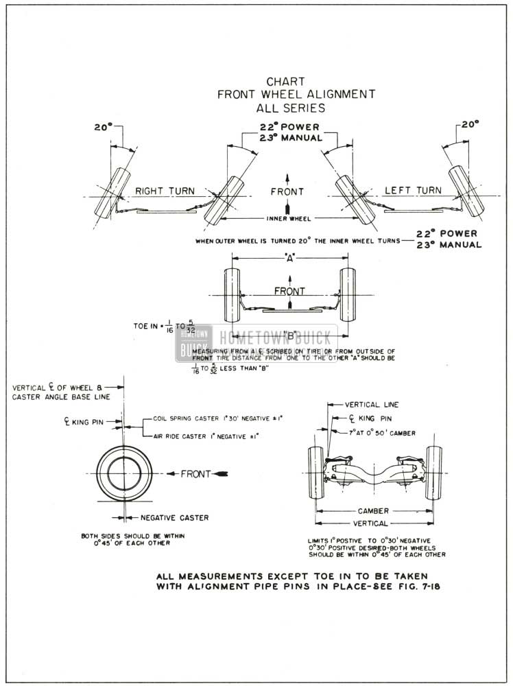
Caster and camber should be within the limits shown in figure 7-19. Note that the caster angles at both front wheels need not be exactly the same but must be within l/2 degree of each other. Likewise, the camber angles on both sides must be within 3,4 degrees of each other. If caster and camber are not within the specified limits, adjust as described below.
1959 Buick Alignment Heights and Specifications Chart
Adjustment of 1959 Buick Caster and Camber
Caster and camber may be adjusted by shimming at either the upper or lower control arm shaft attaching points. If only a small adjustment is needed to bring alignment within limits, lower control arm shaft shimming should provide sufficient adjustment. If a major adjustment is needed, shimming at the upper control arm shaft is recommended. See figure 7-20.
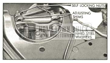
1959 Buick Upper Control Arm Shims
Production adjustment is done at the upper shaft locations using shims of .060″, .080″ and .100″. The .080″ shims are copper-plated for identification. Both round (non removable) and horseshoe (removable) shims are used and at least one of the horseshoe type is used in each of the four upper locations. The horseshoe shims are listed under Group 6.178 of the Master Parts list. No lower control arm shaft shims are installed in production but are available under Group 6.172 in thicknesses of .040″ and .120″.
Adding shims at the front locations (either upper or lower shaft) will change caster toward negative with practically no change in camber. Adding shims at the rear locations (either upper or lower shaft) will change caster toward positive and camber toward negative. Adding equal shims at both front and rear locations, (either upper or lower shaft) will not change caster but will change camber toward negative.
Lower control arm shimming requires loosening the bolts (lower control shaft to frame), one end of shaft at a time, and installing or removing shims between shaft mounting lugs and frame. Maximum shim stack thickness at any one lower location must be limited to .160″. Tighten and torque all bolts, re-check alignment and correct toe-in if necessary. NOTE: Whenever shims are added at the lower location, 300M bolts (1/2″-20″-2 1/8″ long) must be used.
To shim at the upper control arm shaft location, it is necessary to wedge the bolt heads to prevent turning, and loosen both front and rear bolts to free the shims for removal or addition. On the right side, the generator belt tensioning bracket must be removed and the generator swung up out of the way. On the left side it is advisable to disconnect the battery ground strap.
After installing or removing upper shims (limit .380″ in any one stack) tighten and torque upper shaft bolts and re-check alignment before installing generator bracket, etc. If alignment is within limits replace generator bracket and connect battery negative cable. Correct toe-in if necessary. It is imperative to adhere strictly to the torque specifications given in paragraph 7-1.
Checking Theoretical King Pin Inclination
CAUTION: When checking theoretical king pin inclination, car must be on a level surface, both transversely and fore and aft. It must be maintained at specified alignment height while checking (par. 7-17a).
With camber known to be within specified limits, theoretical king pin inclination should check within specified limits given in figure 7-19.
If camber is incorrect beyond limits of adjustment and theoretical king pin inclination is correct, or nearly so, a bent steering knuckle is indicated.
If camber and theoretical king pin inclination are both incorrect by approximately the same amounts, a bent upper or lower control arm is indicated.
There is no adjustment for theoretical .king pin inclination as this factor depends upon the accuracy of the front suspension parts. Distorted parts should be replaced with new parts. The practice of heating and bending front suspension parts to correct errors is not recommended as this may produce soft spots in the metal in which fatigue and breakage may develop in service.
Checking and Adjusting Toe-In
CAUTION: Car must be at curb weight and running height, (DO NOT USE ALIGNMENT PINS-bounce front end and allow it to settle to running height). Steering gear and front wheel bearings must be properly adjusted with no looseness at tie rod ends. The car should be moved forward one complete revolution of the wheels before the toe-in check and adjustment is started and the car should never be moved backward while making the check and adjustment.
- Turn steering wheel to straight ahead position, with front wheels in straight ahead position.
- Measure the horizontal distance from the near edge of front boss of lower control arm shaft to the front edge of brake backing plate, on each side. Adjust tie rods, if necessary, make measurements equal on both sides.
- Using a suitable toe-in gauge, measure the distance between outside walls of tires at the front at approximately 10″ from the floor. See figure 7-19 dimension “A.” Mark points where gauge contacts tires. NOTE: An accurate check also can be made by raising and rotating front wheels to scribe a fine line near the center of each tire, then, with tires on the floor and front end at running height, measure between scribed lines with a suitable trammel.
- Roll the car .forward until measuring points on tires are approximately 10″ from the floor at the rear, .and measure the distance between points used in Step 3 above. The measurement at the front (dimension “A”) should be 1/16″ to 1/8″less than the measurement at the rear (dimension “B”). See figure 7-19.
- If toe-in is not within specified limits, loosen clamp bolts and turn adjusting sleeves at tie rod ends as required. Decrease toe-in by turning left sleeve in same direction as wheel rotates moving forward and turn right sleeve in opposite direction. Increase toe-in by turning both sleeves in opposite direction.
CAUTION: Left and right adjusting sleeves must be turned exactly the same amount but in opposite directions when changing toe-in, in order to maintain front wheels in straight ahead position when steering wheel is in straight ahead position. Tie rod sleeve clamps must be positioned straight down to 45° forward to provide frame clearance.
- After correct toe-in is secured tighten clamp bolts securely.
CAUTION: The steering knuckle and steering arm “rock” or tilt as front wheel rises and falls. Therefore, it is of vital importance to position the bottom face of tie rod end parallel with machined surface at outer end of steering arm when tie rod length is adjusted. Severe damage and possible failure can result unless this precaution is observed.
Checking 1959 Buick Steering Geometry (1959 Buick Turning Angles)
CAUTION: Be sure that caster, camber, and toe-in have all been properly corrected before checking steering geometry. 1959 Buick steering geometry must be checked with the weight of the car on the wheels.
- With the front wheels resting on full floating turntables, turn wheels to the right until the outside (left) wheel is set at 20 degrees. The inside (right) wheel should then set at angle specified in figure 7-19.
- Repeat this test by turning front wheels to the left until the outside (right) wheel sets at 20 degrees; the inside (left) wheel should then set at angle specified in figure 7-19.
- Errors in 1959 Buick steering geometry generally indicate bent steering arms, but may also be caused by other incorrect front end factors. If the error is caused by a bent steering arm it must be replaced. Replacement of such parts must be followed by a complete front end check as described above.
Leave A Comment
You must be logged in to post a comment.