SECTION 3-H – 1959 BUICK ROCHESTER 4-BARREL CARBURETOR
3-27 DESCRIPTION AND OPERATION OF 1959 BUICK ROCHESTER 4-BARREL CARBURETOR
General Description
The Rochester Model 4GC used on Series 4600-4700-4800 engines is a 4-barrel downdraft type which provides the advantages of a compound installation of two 2-barrel carburetors in one compact unit. See figure 3-75.
1959 Buick Rochester 4-Barrel Carburetor
To aid description and the proper identification of parts the 1959 Buick Rochester 4-barrel Carburetor is considered to be divided into a primary section and a secondary section.
The primary section covers the 2-barrelled forward half of the 1959 Buick Rochester 4-barrel Carburetor assembly. This section is essentially a complete 2-barrel carburetor containing a float system, idle system with adjustable needle valves, main metering system, power system, and accelerating system. This section also includes a carburetor starter switch for starting the engine, and the automatic choke mechanism.
The secondary section covers the 2-barrelled rearward half of the 1959 Buick Rochester 4-barrel Carburetor assembly. This section is essentially a supplementary 2-barrel carburetor which cuts in to assist the primary section when a pre-determined throttle opening and engine RPM are reached. This section contains a float system, a non-adjustable idle system, and a main metering system. It has a separate set of throttle valves and a set of auxiliary valves, which are located in the barrels above the throttle valves.
The primary throttle valves are operated by the accelerator pedal and the connecting throttle linkage. The secondary throttle valves are operated by the primary throttle valve shaft through delayed action linkage which permits a predetermined opening of the primary valves before the secondary valves start to open. Action of the linkage then causes both sets of throttle valves to reach the wide open position at the same time.
The starter switch, which is operated by the primary throttle valve shaft, is fully described in paragraph 10-30. The other systems of the 1959 Buick Rochester 4-barrel Carburetor are described in the following subparagraphs.
Operation of Float Systems
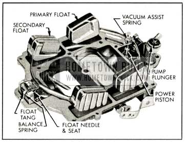
Each section of the 1959 Buick Rochester 4-barrel Carburetor has a separate and independent float system, consisting of a float chamber formed by a partition in the main body, a 2-pontoon float, a needle valve seat and valve. A vacuum assist device (on the primary float only) aids in maintaining the correct fuel level in the bowl. Fuel enters the 1959 Buick Rochester 4-barrel Carburetor through the inlet port in the primary side of the air horn. From this point fuel flows to the separate float chambers through a horizontal passage in the air horn. There is a fuel strainer located just above each needle seat on both the primary and secondary side. See figure 3-76.
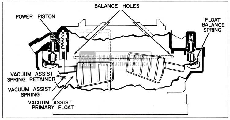
1959 Buick Rochester Carburetor Primary and Secondary Float Systems
When the fuel reaches the prescribed level in each float chamber the float moves the needle valve against its seat to shut off the flow of fuel. The needle valves are connected to the float levers by clips. Because of these, the needle valves will be pulled from their seats if stickiness is encountered due to gum formation.
On the primary side, a coiled spring located on the power piston stem acts as an assist in closing the primary inlet needle on its seat by exerting pressure on a tang located on the float arms at the center. The only time the vacuum assist spring applies pressure to the tang on the float lever is during 1959 Buick Rochester 4-barrel Carburetor idle and part throttle operation. Under these conditions, the power piston is in the full up position. During heavy acceleration and power system operation, the power piston drops and releases all pressure applied to the floats to hold them closed. This allows maximum float drop and full fuel flow to eliminate the possibility of dry jets and engine cut-out. See figure 3-76.
On the secondary side, the float is spring loaded at the rear tang. The purpose of this balance spring is to give a more positive closing of the needle valve. The spring tension against this tang determines float drop and also helps determine fuel level.
There is a cored passage located in the side of the 1959 Buick Rochester 4-barrel Carburetor body which links the fuel chambers on the primary and secondary sides together. In this way, any abnormal rise in fuel in one side of the 1959 Buick Rochester 4-barrel Carburetor bowl will automatically balance with the other side.
The joint between the air horn and the main body is sealed by a gasket, and the float chambers are vented by passages which are calibrated to provide proper air pressure above the fuel under all operating conditions. These passages in the air horn lead into the throat of the air horn, and to outside atmosphere. The amount of fuel metered by the 1959 Buick Rochester 4-barrel Carburetor depends on the air pressure on the fuel in the float bowl. The external vents permit fumes to escape from the float chambers when the engine is idling or stopped after extremely hot operation.
Operation of Idle (Low Speed) Systems
Each barrel of the 1959 Buick Rochester 4-barrel Carburetor has a separate idle system but the general operation is identical in all barrels. The idle system in each barrel supplies fuel to the engine whenever the position of the throttle valve is such that suction is created at the idle discharge holes in the throttle body.
Suction on an idle discharge hole causes fuel in the float chamber to flow through the main metering jet and upward into the idle tube which meters the fuel. Calibrated bleed holes permit air to enter at the top and side of the idle passage in the cluster so that a mixture of fuel and air passes down the idle channel to the idle discharge holes. Additional air is draw n into the fuel-air mixture in the idle channel through lower idle air bleeds which are in the primary side of the main body. See figure 3-77.
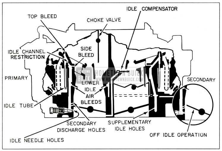
1959 Buick Rochester Carburetor Primary and Secondary Idle Systems
When the throttle valve is closed, the fuel air mixture is supplied through the lower idle discharge holes only, since the upper holes are above the valve and are not affected by suction. As the throttle valve is opened, suction is also placed on the upper idle discharge holes which then feed additional fuel-air mixture into the engine. With continued opening of the throttle valve the suction on the idle discharge holes tapers off until a point is reached where the idle system no longer supplies fuel-air mixture. Before this point is reached however, the main metering system has begun to supply fuel, as described later.
The lower idle air bleeds discharge fuel after the idle systems cease to operate, thereby keeping fuel immediately available in the idle channels at a point very near the idle discharge holes and also enriching the mixture being delivered by the main metering system.
In the primary section, the quantity of fuel air mixture supplied through the lower idle discharge holes is controlled by the idle needles, which may be adjusted to provide smooth engine idle operation. In the secondary section, the quantity of idle fuel-air mixture is controlled by the fixed size of discharge holes located in the rear of the secondary throttle bores.
On the secondary side of the float bowl, a thermostatic valve allows additional air to enter the primary bores under extreme hot idle conditions. This valve, called the “idle compensator”, is operated by a bi-metal strip which senses temperature. See figure 3-78.
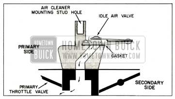
1959 Buick Rochester Carburetor Idle Compensator
In a prolonged hot idle the bi-metal strip bends, raising the valve and uncovering a hole leading to the underside of the primary throttle valves. The additional air drawn into the engine in this manner is sufficient to offset the enrichening effects of high temperatures and prevent hot idle stalling. When under hood temperatures are lowered , the valve closes and operation returns to normal. This valve cannot be repaired, so a defective valve must be replaced.
Operation of Main Metering Systems
Each barrel of the 1959 Buick Rochester 4-barrel Carburetor has a separate main metering system; however, the operation of all systems is identical. The main metering system in each barrel supplies fuel to the engine whenever the position of the throttle valve is such that the incoming air stream creates suction on the main discharge nozzle.
Air entering the barrel through the air horn passes through the venturi tubes which increase the velocity of the air and create a suction on the main discharge nozzle. This causes fuel to flow from the float chamber through the main metering jet into the main discharge
nozzle. Air is drawn in through the high speed bleeder so that a mixture of fuel and air is discharged from the main discharge nozzle into the air stream passing through the small venturi in the barrel of the 1959 Buick Rochester 4-barrel Carburetor. See figure 3-79.
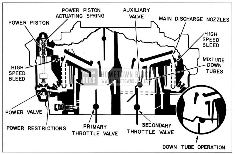
1959 Buick Rochester Carburetor Main Metering and Power Systems
The main metering systems in the primary section control the flow of fuel during the intermediate or part throttle range of operation and up to approximately 85 MPH if the car is accelerated gradually. The secondary throttle valves remain closed until the primary valves have opened approximately 40-44 degrees, after which they are opened proportionately so that all valves reach the wide open position at the same time. While the secondary throttle valves are closed, the auxiliary valves located above them are held closed by the spring tension on the auxiliary valve shaft; therefore, there is not sufficient air flow through the barrels to operate the main metering systems in the secondary section.
When the secondary throttle valves are open and engine speed is about 1600 RPM, the resulting air flow through the secondary barrels starts to open the auxiliary valves because their supporting shaft is located off-center in the barrels. The auxiliary valves will be fully open at approximately 2800 RPM. When the auxiliary valves are open the main metering systems in the secondary section also supply fuel to the engine. See figure 3-79.
During the period in which the secondary throttle valves are open and air flow is not high enough in the secondary bores to open the auxiliary valves, additional fuel is needed for the air which bypasses around the auxiliary valves. This additional fuel is supplied by tubes which extend from the mixture channel in the venturi cluster arm to the low pressure point below the closed auxiliary valves. The tubes are slashed on the bottom to provide a smoother transition between the opening of the secondary valves and the opening of the auxiliary valves. When the air flow is high enough to open the auxiliary valves, the down tubes no longer feed the fuel because the low pressure point is now in the small venturi. With this feature the correct fuel /air mixture is supplied at any point during secondary throttle valve operation.
Operation of the Power System
For maximum power under load or for all speeds above approximately 85 MPH, a richer mixture is required than that necessary for normal throttle opening. This additional fuel is provided by one power system connected to the main metering systems in the primary section of the 1959 Buick Rochester 4-barrel Carburetor. See figure 3-79.
The power piston cylinder in the air horn of the 1959 Buick Rochester 4-barrel Carburetor is connected by a channel to the face of the mounting flange so it is subject to intake manifold vacuum. At part throttle position the vacuum is sufficient to hold the power piston in its “up” position against the tension of the piston spring. When the throttle valves are opened to a point where manifold vacuum drops to approximately 9 to 5 inches of mercury and additional fuel is required for satisfactory operation, the piston spring moves the power piston down to open the power valve. This allows additional fuel to enter the main discharge nozzles in the primary section through calibrated restrictions located below the main metering jets. See figure 3-79.
Operation of the Accelerating System
For smooth and rapid acceleration it is necessary to supply an extra quantity of fuel momentarily when the throttle is opened suddenly. This is accomplished by one accelerating pump piston which is directly connected to the primary throttle shaft lever by means of a rod and pump lever.
When the throttle is closed, the pump piston moves up and draws a supply of fuel from the float chamber through the inlet strainer, past the inlet ball check valve and into the pump cylinder. When the throttle is opened, the piston on its downward stroke exerts pressure on the fuel which closes the inlet check ball and opens the outlet check ball. A metered quantity of fuel is then discharged through the pump discharge nozzles into each barrel in the primary section of the 1959 Buick Rochester 4-barrel Carburetor. This occurs only momentarily during the accelerating period. The pump duration spring which is compressed by the downward movement of the pump linkage against the resistance of the fuel provides a follow-up action so that the discharge carries out over a brief period of time. A ball check in the accelerator pump plunger acts as a vapor vent to prevent vapor pressure from forcing fuel from the pump discharge holes during extreme heat periods. Downward movement of the plunger, however, seats the ball and allows normal operation of the accelerating system. See figure 3-80.
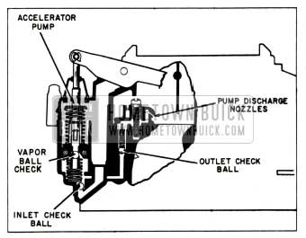
1959 Buick Rochester Carburetor Accelerating System
When the desired speed is reached and the throttle is held in a fixed position, the pressure on the fuel decreases sufficiently so that the outlet check ball closes and fuel ceases to discharge from pump nozzles. Thus a quantity of fuel is maintained in the channel adjacent to the outlet check ball where it is immediately available for future requirements.
3-28 DESCRIPTION AND OPERATION OF ROCHESTER AUTOMATIC CHOKE
General Description
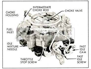
The automatic choke mechanism is contained in the primary section of the 1959 Buick Rochester 4-barrel Carburetor. It consists of a choke valve mounted on a shaft in the 1959 Buick Rochester 4-barrel Carburetor air horn connected through linkage to a thermostat mounted on the 1959 Buick Rochester 4-barrel Carburetor throttle body. The thermostat contains a bimetal spring and a vacuum actuated piston. A choke rod connects the choke valve to a fast idle cam on the throttle body. A heat pipe connects the choke housing to a heat stove in the right exhaust manifold.
The choke valve is mounted off-center in the choke shaft so that the force of the air stream passing through the air horn tends to move the valve to the open position. A short lever mounted on the intermediate choke shaft in the choke housing is engaged by the free outer end of the thermostat which, when cold, tends to close the choke valve. The piston, which is actuated by intake manifold vacuum, is connected by a link to the short lever on the inter-
mediate choke shaft and tends to open the choke valve when the engine fires. See figure 3-81.
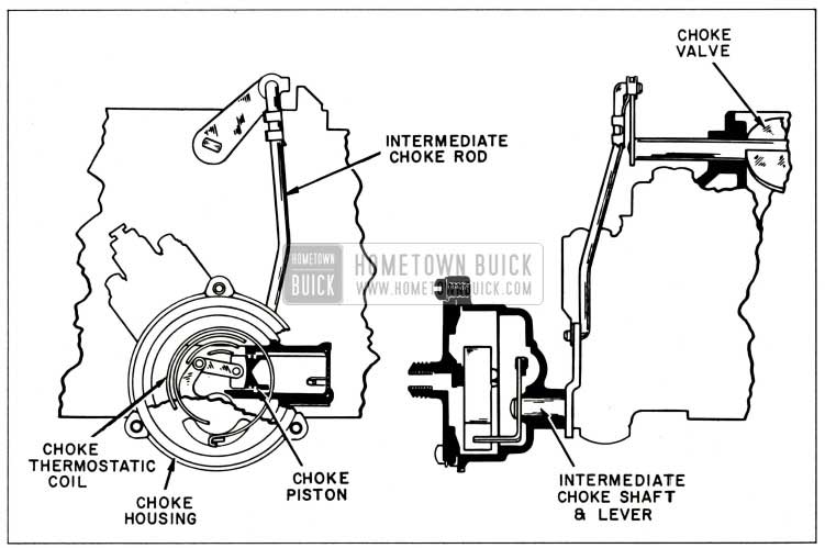
1959 Buick Rochester Carburetor Choke System
The heat stove in the 1959 Buick exhaust manifold heats the air which is drawn through it and the heat pipe into the choke housing. A restriction in the choke housing cover regulates the quantity of air flowing into the choke housing to heat the thermostat.
The fast idle cam is connected by the choke rod to a lever on the outer end of the choke shaft so that it is rotated as the choke valve moves. In closed throttle position, the fast idle screw bears against one edge of the fast idle cam which has a number of steps of different heights to give different amounts of throttle opening, depending on positions of the cam and choke valve.
Choke Operation-Cold Engine
When the engine becomes cold the choke thermostat also becomes cold and increases its spring tension sufficiently to close the choke valve. It is prevented from closing the valve, however, because the fast idle screw holds the fast idle cam in the slow idle position ; consequently, the choke valve is held partially open.
When the accelerator pedal is depressed to start the engine, the throttle stop screw is lifted clear of the fast idle cam and the thermostat then closes the choke valve. When the engine starts, intake manifold vacuum causes the piston to partially open the choke valve against the spring tension of the thermostat, thereby admitting sufficient air to give a satisfactory running mixture.
When the accelerator pedal is released after starting the engine, the fast idle screw comes to rest against a step of fast idle cam which was rotated to the fast idle position by the closing of choke. This provides proper throttle opening to prevent stalling of the cold engine.
If the throttle is partially opened while the running engine is cold, the increased force of air flow against the off-set choke valve will open the valve against the spring tension of the thermostat. These opposing forces balance the choke valve at a position which provides the required choke action without causing loading or an excessively rich mixture.
Choke Operation-Warm-Up Period
As the engine and exhaust manifold warm up, warm air is drawn through the heat pipe into the choke housing by manifold vacuum. This warms the thermostat, causing it to reduce its spring tension on the choke valve in proportion to the increase in temperature. This, in turn, allows the choke valve to be opened by the combined forces of air velocity on the valve and vacuum on the choke piston.
When the throttle is opened and the fast idle screw is lifted from the fast idle cam, the choke rod and cam drop by their own weight to bring a lower step into position for the throttle stop screw. The engine will then run at a lower speed at closed throttle.
Choke Operation-Hot Engine
When the engine reaches normal operating temperature, the choke thermostat is heated to the point where it no longer exerts any spring tension on the choke valve. The choke valve is in the wide open position and the fast idle cam is in the slow idle position so that the fast idle screw misses the cam completely. The throttle stop screw now takes over in determining curb idle speed.
Choke Unloader Operation
If the engine becomes flooded for any reason, the choke valve can be partially opened by depressing the accelerator pedal to the full extent of its travel. This causes an arm on the throttle lever to contact and rotate the fast idle cam, which forces the choke valve open.
Secondary Lock-out Operation
The secondary section does not have a choke valve in the air horn. In order to prevent air from entering the 1959 Buick Rochester 4-barrel Carburetor through the secondary side during the engine warm-up period it is necessary to block the movement of the secondary throttle valves by means of the lock-out slot in the fast idle cam.
When the choke valve is in any position except wide open, it holds the fast idle cam up from its lowest position. This causes a lock-out slot in the fast idle cam to engage a tang on the secondary throttle shaft lever which prevents the secondary throttle valves from opening.
When the choke is wide open the fast idle cam and lock-out slot plate drops to its lowest position; the secondary throttle shaft tang is then free to move along a contour in the fast idle cam and the secondary valves can open.
3-29 ADJUSTMENT OF FAST IDLE CAM, CHOKE UNLOADER, AND SECONDARY THROTTLE LOCK-OUT
- Close throttle so that fast idle screw contacts second highest step of fast idle cam with side of screw against rise to high step of cam, then check clearance between choke valve and air horn dividing wall using .152″ Gauge (No. 24 drill) . See figure 3-82.
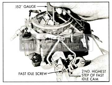
1959 Buick Rochester Carburetor Checking Fast Idle Cam Adjustment
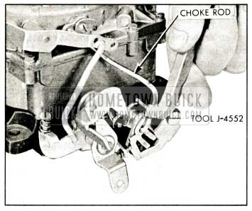
1959 Buick Rochester Carburetor Adjusting Fast Idle Cam
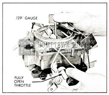
1959 Buick Rochester Carburetor Checking Choke Unloader Adjustment
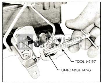
1959 Buick Rochester Carburetor Adjusting Choke Unloader
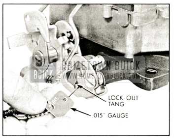
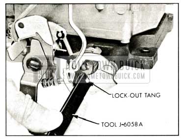
1959 Buick Rochester Carburetor Checking Secondary Lock-Out Adjustment
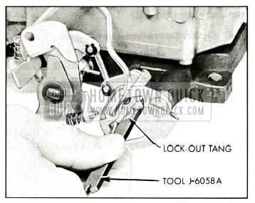
1959 Buick Rochester Carburetor Adjusting Secondary Lock-Out
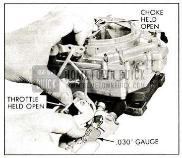
1959 Buick Rochester Carburetor Checking Secondary Contour Adjustment
1959 Buick Rochester Carburetor Adjusting Secondary Contour
3-30 DISASSEMBLY, CLEANING, AND INSPECTION OF 1959 BUICK ROCHESTER 4-BARREL CARBURETOR
- Remove spring clip from upper end of intermediate choke rod and disengage rod from choke shaft lever. See figure 3-90.
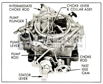
1959 Buick Rochester Carburetor Exterior Linkage
1959 Buick Rochester Carburetor Air Horn Parts
1959 Buick Rochester Carburetor Main Body Parts
3-31 ASSEMBLY AND ADJUSTMENT OF 1959 BUICK ROCHESTER 4-BARREL CARBURETOR
When assembling the 1959 Buick Rochester 4-barrel Carburetor, use all new gaskets and any additional new parts found to be necessary during inspection. Calibrated parts must be as specified for carburetor CODE number.
- With main body inverted on bench, place auxiliary throttle body assembly in its proper position with screw heads toward top of 1959 Buick Rochester 4-barrel Carburetor. Check to make sure it is flush or slightly below main body casting.
- Place new gasket on main body and install throttle body assembly and screws.
- If removed, install throttle stop screw and fast idle screw with springs (throttle stop screw has a round point; fast idle screw has a flat point). Install vacuum line fitting. Install both idle mixture needles and their springs. Seat needles lightly and back out 1% turn, which will provide an average starting adjustment. Forcing needles hard against seats will score them and ruin them for service.
- Place throttle body and main body assembly in upright position on bench or mounting fixture. Install new starter switch strainer if old strainer was removed. Install starter switch ball, plunger, guide block assembly, spring, terminal cap, and screws in throttle body. See figure 10-26. Lubricate switch as described in paragraph 10-30 and check switch timing if there is any indication that switch is not functioning properly.
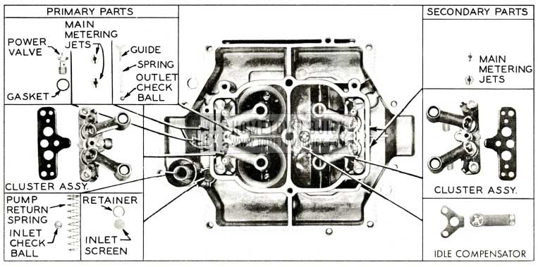
- Install idle compensator using a new gasket. Install secondary cluster assembly using a new gasket. This cluster has no pump discharge nozzles.
- Install all four main metering jets. These jets have tapered seats and do not require gaskets. NOTE: The primary jets are the two having the smaller holes and are installed in the pump side of the body.
- Install pump outlet check ball. This is a steel ball and is larger than the pump inlet ball. Install pump outlet ball spring and spring guide.
- Install primary cluster assembly, screws, lock washers, and new gasket in pump side of 1959 Buick Rochester 4-barrel Carburetor.
- Install new pump inlet screen and retainer if old screen was removed.
- Install pump inlet check ball (small aluminum) and pump return spring. NOTE: Never substitute a steel ball for the aluminum ball.
- Install power valve and gasket.
- Assemble choke piston and pin to choke piston lever and connecting link, making sure that pin hole in piston is opposite from tang on lever. Then install in thermostat housing. Install intermediate choke shaft, lever, and rod assembly in choke housing with lever hanging down. Connect choke piston lever to intermediate choke shaft with screw. Do not use lubricant of any kind on piston or in cylinder.
- Install thermostat housing on throttle body using a new gasket.
- Install pump plunger assembly and rubber boot in inverted air horn. Install power piston actuating spring and power piston assembly and stake securely in air horn. Do not damage coil spring and cup on stem. Power piston must be free in any position.
- Install new air horn gasket. Install a fuel inlet strainer on inlet side of each needle seat. Install float needle seats and gaskets. Install float needles, floats, and hinge pins making sure that secondary float tang is placed outside balance spring. NOTE: All primary and secondary float system parts should go back in their same positions, thereby holding need for float adjustments to a minimum. The float needles are also matched to their respective seats and should never be mixed.
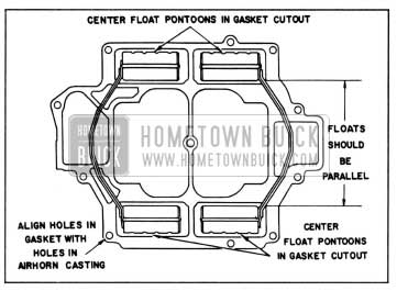
- Adjust Primary Float Level and Align Float. Make all float adjustments with gasket in place.
- with air horn inverted, install Gauge J-7182-1 under primary float. Hold gauge in vertical position with tang on gauge against shoulder of air horn casting. See figure 3-93.
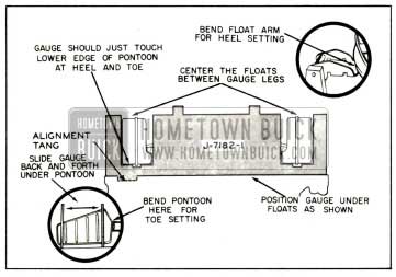
1959 Buick Rochester Carburetor Primary Float Level Adjustment and Alignment
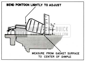
- With air horn inverted, install Gauge J-7182-1 vertically over secondary float at heel of pontoons. See figure 3-94.
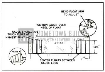
1959 Buick Rochester Carburetor Secondary Float Level Adjustment and Alignment
1959 Buick Rochester Carburetor Secondary float Toe Adjustment
1959 Buick Rochester Carburetor Float Alignment Check
- Hold air horn so that floats are hanging down.
- Hold power piston in full up position by placing thumb nail at brass portion of power piston. See figure 3-97.
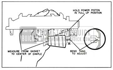
1959 Buick Rochester Carburetor Primary Float Drop Adjustment-with Vacuum Assist
- Hold air horn so that floats are hanging down. Do not hold power piston as in previous adjustment.
- With power piston stem released and fully extended, measure distance from gasket to center of dimple on pontoon. Distance should be 1 1/2 “. See figure 3-98.
1959 Buick Rochester Carburetor Primary Float Drop Adjustment-without Vacuum Assist
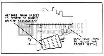
- Hold air horn so that floats are hanging down. Bounce floats lightly before measuring distance.
- Measure distance from gasket to center of dimple on pontoon. Distance should be 1 5/16″. See figure 3-99.
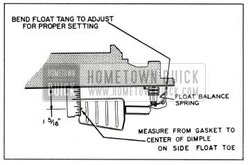
1959 Buick Rochester Carburetor Secondary Float Drop Adjustment
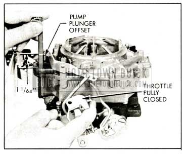
1959 Buick Rochester Carburetor Checking Pump Plunger Adjustment
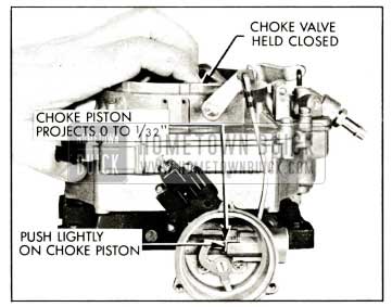
1959 Buick Rochester Carburetor Checking Choke Piston Adjustment
If adjustment is required, bend intermediate choke rod using Tool J-5197. See figure 3-102.
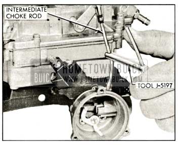
1959 Buick Rochester Carburetor Adjusting Choke Piston
- Push fast idle cam to full up position so that fast idle screw contacts high step of cam. (b) Adjust fast idle screw until engine is running 1500 RPM.
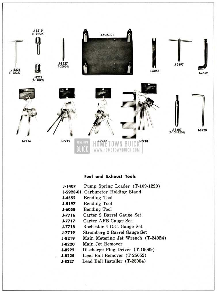
1959 Buick Fuel and Exhaust Special Tools
Leave A Comment
You must be logged in to post a comment.