SECTION 3-C – 1959 BUICK FUEL SYSTEM ADJUSTMENTS AND REPLACEMENTS – EXCEPT IN PUMP AND CARBURETOR ASSEMBLIES
3-7 1959 BUICK AIR CLEANER, GAS FILTER, AND MANIFOLD VALVE SERVICE
1959 Buick Air Cleaner Service
An air cleaner with a dirty element will restrict the air flow to the carburetor and cause a rich mixture at all speeds. The device will not properly remove dirt from the air and the dirt entering the engine will cause abnormal formation of carbon, sticking valves, and wear of piston rings and cylinder bores.
Regular cleaning and inspection of the element at 5000 mile intervals (or more frequently in dusty territory) is necessary to prevent excessive engine wear and abnormal fuel consumption. The procedure for cleaning the air cleaner is given under Lubricare Instructions, paragraphs 1-2.
Cleaning 1959 Buick Gasoline Filter
The 1959 Buick gasoline filter or strainer is of the glass bowl type and is located in the line between the 1959 Buick fuel pump and the carburetor. The filter is mounted on a separate bracket which is attached under one of the thermostat housing bolt. In this location, the bowl can be inspected or cleaned conveniently without removing the air cleaner.
The filter element has a large filtering area. It is of fine enough material to assure that any particles which pass through it are too small to interfere with the operation of the float needle and seat, and also too small to cause clogging of the smallest passages in the carburetor. This element prevents the passage of water under ordinary conditions; however, water or other foreign matter should never be allowed to collect in the bowl until it reaches the lowest part of the filtering element. To prevent this possibility, the glass bowl should be visually inspected at each 1000 mile Lubricare period and cleaned if necessary. See paragraph 1-1.
To clean the filter, remove the bowl and dump the contents. Soak the bowl in a good cleaning solvent to loosen any deposits. Visually inspect the filtering element and gaskets ; replace if necessary. Wipe the bowl clean with a clean cloth and reinstall, tightening thumb nut finger tight.
After assembling the 1959 Buick fuel filter, always start the engine and observe the filter carefully to make sure that the gasket is not leaking.
Cleaning 1959 Buick Carburetor Gasoline Strainers
A fine mesh strainer is located in some carburetor inlets. This strainer should seldom require cleaning because of the gasoline filter which precedes it in the gasoline supply line. This strainer should be inspected however, if fuel supply at carburetor inlet is adequate but carburetor operation indicates lack of fuel.
Freeing Up Sticking 1959 Buick Exhaust Manifold Valve
Lubrication of the 1959 Buick exhaust manifold valve shaft every 1000 miles is specified in Lubricare Instructions (par. 1-1).
Carbon or lead salt deposits around the valve shaft may cause the valve to stick or become sluggish in operation. A valve sticking in the open position will cause slow engine warm up, excessive spitting and sluggish engine operation when cold. A valve sticking in the closed position will cause overheating, loss of power, and hard starting when the engine is hot, and may also cause warped or cracked manifolds. Sticking in either position will adversely affect fuel economy.
If the valve shaft is sticking or frozen in the manifold, free it up by tapping on the ends with a light hammer, and by rotating the counterweight. Penetrating oil or kerosene may be used to aid in freeing the shaft. When the valve shaft is free, apply a mixture of kerosene and powdered graphite liberally to the shaft bearing ; the mixture to be composed of 2 1/2 ounces of powdered graphite to 1 pint of kerosene.
Checking 1959 Buick Manifold Valve Thermostat Setting
The setting of the 1959 Buick exhaust manifold valve thermostat may be checked when the engine is at room temperature of approximately 70° F. Unhook the outer end of thermostat from anchor stud on the manifold and hold the valve in the closed position. To bring the end of thermostat to the anchor stud will then require approximately 1/2 turn wind-up of the thermostat as shown in figure 3-9.
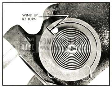
1959 Buick Valve Thermostat Wind-Up
The thermostat is not adjustable and should never be distorted or altered in any way as this will affect its calibration. If the thermostat does not have the proper setting, or is damaged, it should be replaced.
3-8 1959 BUICK CARBURETOR IDLE AND AUTOMATIC CHOKE ADJUSTMENTS
Carburetor adjustment should not be attempted until it is known that all items affecting engine Ignition and Compression are in good order, as outlined in paragraph 2-9. Any attempt to adjust or alter the carburetor to compensate for faulty conditions elsewhere in items affecting engine performance will result in reduced fuel economy and overall performance.
Initial Setting of Idle Needle Valves and Throttle Stop Screw
- With engine stopped, turn both idle needle valves clockwise until they are lightly seated. Forcing valves hard against seats will score valves and seats and ruin them for proper adjustment.
- Now turn each needle OUT one full turn. This setting should give an approximate idle mixture so that engine can be warmed up for final adjustment as described below.
- Back off throttle stop screw and hold fast idle cam in HOT (choke open) position so that throttle valves are fully closed.
- On all carburetors, turn throttle stop screw IN (clockwise) until it just contacts, then turn screw IN one complete turn. This setting should give an approximate idling speed so that engine can be warmed up for final adjustment as described below. For more exact initial settings, see specifications for carburetor being adjusted.
Final Adjustment of Idle Needle Valves and Throttle Stop Screw
- With throttle stop screw and idle needle valves at the initial settings described above (subpar. a), start the engine and run it until it is at normal operating temperature. CAUTION: Idle mixture and speed adjustments cannot be made satisfactorily wit h an abnormally hot engine. On any 4-barrel carburetor (with a hot idle compensating valve ) it is particularly important that idle adjustments be made at normal temperature so that this valve will be closed.
- With engine at normal operating temperature and idling at 485 RPM (550 RPM on air conditioned cars) in neutral or park, adjust one needle valve at a time (fig. 3-10) to provide smooth idle, as follows:
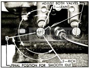
1959 Buick Adjustment of Idle Needle Valves
- Slowly turn needle valve “IN” (clockwise) until engine just begins to lag or run irregularly because of lean mixture.
- Slowly turn needle valve “OUT” until engine just begins to “roll” or “gallop” because of rich mixture.
- Slowly turn needle “IN” just enough to provide the smoothest engine operation.
- Repeat this same procedure on the other needle valve.
Regardless of the method s or instruments used for making adjustments in the shop, the correctness of adjustment should be finally checked by a road test for smoothness at idling speed , power on acceleration, and freedom from sluggishness or fiat spots throughout entire speed range.
Automatic Choke Adjustments
The choke thermostat is calibrated to give satisfactory performance with regular blends of fuel when it is placed at the standard factory setting, which is listed in the specifications for each carburetor.
When it is necessary to adjust the thermostat loosen the housing or cover attaching screws and turn as required. On Stromberg and Rochester chokes it is also necessary to loosen the heat pipe connection to turn the cover. When tightening heat pipe connection after adjustment do not use excessive pressure, which may change position of thermo stat cover. Also, wrench should be over slotted area of connector or spreading may result.
Thermostat settings other than standard should be used only when the car is habitually operated on special blends of fuel which do not give satisfactory warm-up performance with the standard setting. A “Lean” setting may be required with highly volatile fuel which produces excessive loading or rolling of engine on warm-up with the standard thermostat setting. A “Rich” setting should be used only when excessive spitting occurs on engine warm-up with the standard thermostat setting. When making either a “Lean” or “Rich” setting, change one point at a time and test results with engine cold, until the desired performance is obtained.
If the engine operates on fast idle too long after starting or else moves to slow idle too soon, or the choke unloader does not operate properly, check the fast idle and choke unloader adjustments as described in paragraph
3-9 1959 BUICK THROTTLE LINKAGE AND DASH POT ADJUSTMENTS
The procedure for adjusting 1959 Buick throttle linkage is identical on synchromesh and automatic transmission cars. On automatic transmission cars, however, the throttle linkage actuates other linkage connected to the stator control valve. Also, automatic transmission cars have a dash pot to prevent engine stalling from too rapid release of the accelerator pedal. Therefore, a stator linkage adjustment and a dash pot adjustment are required on automatic transmission cars in addition to the adjustments necessary on synchromesh cars.
1959 Buick Throttle Linkage Adjustment
- Make sure that accelerator pedal is in good condition and that floor mat is properly installed. Make sure pedal ball studs are tight in floor pan.
- Check throttle linkage for proper lubrication. Make sure that pedal rod does not bind going through dash, and make sure that return spring fully closes the throttle.
- On automatic transmission cars only, move 1959 Buick throttle lever to wide o pen position and make sure stator linkage does not prevent throttle from opening completely. With throttle wide open, stator rod should still have a slight amount of free movement ; if stator rod is not free, make stator linkage adjustment (subpar. b) before proceeding with 1959 Buick throttle linkage adjustment.
- Disconnect throttle rod from throttle operating lever. See figure 3-11.
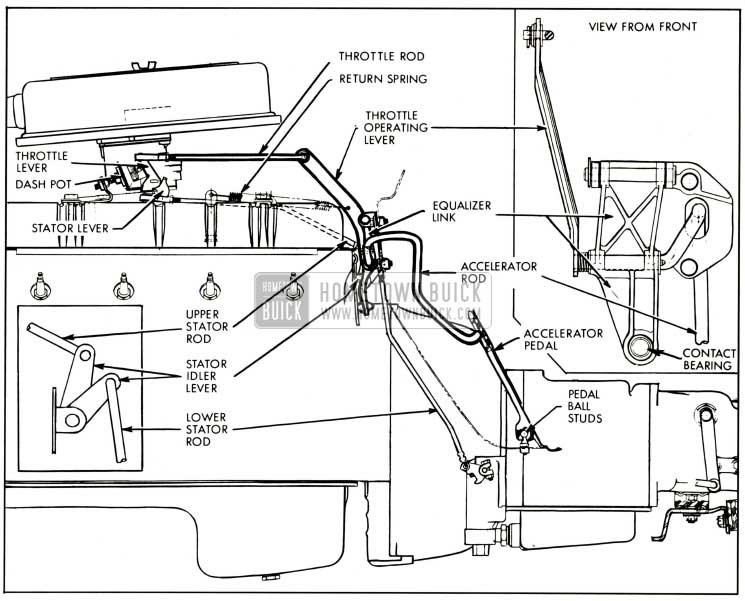
1959 Buick Throttle and Stator Control Linkage Twin Turbine Transmission
1959 Buick Stator Linkage Adjustment (Automatic Transmission Cars)
- With 1959 Buick throttle held in wide open position, adjust upper stator rod so that ball joint at forward end will just slip freely in stator lever on carburetor with stator rod pulled forward and stator lever held rearward against pickup. See figure 3-11.
- Now lengthen stator rod 1 turn. This provides a slight clearance at stop in transmission to make sure carburetor will reach wide-open throttle.
- Reconnect ball joint to stator lever and tighten lock nut.
- Check stator linkage adjustment by moving throttle lever to wide open position; then move stator rod endwise to make sure it has a slight free movement or “shake”.
1959 Buick Dash Pot Adjustment (All Auto. Trans.)
Adjust the 1959 Buick dash pot only after the throttle linkage and stator lever adjustments have been made as described above (subpar. a and b) and the engine is at normal operating temperature.
- Open throttle to clear fast idle cam, rotate cam to extreme fast idle position, and allow throttle to lose against fast idle cam. See figure 3-12.
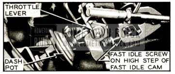
1959 Buick Dash Pot Adjustment
3-10 REPLACEMENT OF 1959 BUICK GASOLINE TANK OR FILLER
The same gasoline tank is used on all series cars. However, 3 different fillers are used. All series cars except Series 4800 and estate wagons use one tank and filler assembly. Series 4800 cars have a longer filler and estate wagons have a hose clamped between a filler and the tank.
The 1959 Buick gas gauge tank unit is combined with the feed pipe. It is necessary to lower the gas tank to replace this assembly. See figure 3-1.
Before condemning a gas gauge tank unit, make sure that all dirt is cleaned from around the terminal; also make sure that the wire is securely fastened to the terminal and that the insulating flap is folded over and snapped over the wire. An accumulation of road dirt around the gauge terminal may permit an electrical leak that will affect the accuracy of the gauge.
To remove a gasoline tank, first remove the drain plug and drain the gas into a clean container. Disconnect the feed hose from the feed pipe. Disconnect the vent hose from the breather pipe. Pull the wire to the gas gauge tank unit apart at the connector. Disconnect the support straps at their rear ends and remove the tank.
To install a gasoline tank, reverse the above procedure used for removal. Make sure that the wire to the gas gauge tank unit is clipped to the top of the tank.
Leave A Comment
You must be logged in to post a comment.