SECTION 5-E – 1959 BUICK TRIPLE TURBINE TRANSMISSION TROUBLE DIAGNOSIS, LINKAGE ADJUSTMENT
1959 BUICK TRIPLE TURBINE TRANSMISSION TEST, INSPECTION, ADJUSTMENT ON CAR
5-32 1959 BUICK TRIPLE TURBINE TRANSMISSION TEST AND INSPECTION
Road Test
When improper operation of a 1959 Buick Triple Turbine transmission is reported, time and expense can usually be saved by first making a thorough road test to observe operation in all ranges under appropriate driving conditions. The road test will also serve to thoroughly warm up the 1959 Buick Triple Turbine transmission, which is required for any tests made in the shop.
The person making the road test should be familiar with the operation and performance of 1959 Buick Triple Turbine Transmission in all ranges so that he will be able to detect any sub-standard condition. The required “feel” of a Triple Turbine Transmission can best be acquired by driving through a test routine on a number of cars whose performance is known to be satisfactory. Knowledge of which parts are in operation and which hydraulic controls govern operation in each range is essential to intelligent diagnosis, therefore, a study of Paragraph 5-34 is recommended.
After the 1959 Buick Triple Turbine transmission has been warmed up to normal operating temperature, thoroughly test operation in all ranges, making tests on steep grades as well as on level roads, if possible.
While in “D” range test shifting of the stator by depressing the accelerator pedal. As the accelerator pedal is depressed beyond half way a change of engine speed accompanied by acceleration pick-up should be noted, indicating that the stator blades are starting to move toward the high angle position.
Shift to Grade Retard “G” range, clutch should engage immediately. A definite braking action should be experienced at car speeds above 15 MPH.
Check for abnormal slip or over-run of the engine on low speed acceleration. With car stopped on level road and brakes released, check for creep when engine is accelerated with 1959 Buick Triple Turbine transmission in Neutral. Little or no creep should be evident. Check for abnormal creep with engine idling and transmission in each of the driving ranges.
Place 1959 Buick Triple Turbine transmission in Drive and firmly apply brakes. Snap the throttle open to give engine speed of approximately 1400 RPM and immediately release the accelerator pedal. If the engine returns to idle too slowly, or returns to idle so fast that it either stalls or rolls unevenly, improper throttle linkage and dash pot adjustment is indicated. Rough operation on idle after slow deceleration indicates the need for engine tune-up adjustments.
During all tests, be alert for any unusual or abnormal noises. Carefully note the range, speed and other conditions under which the noise is evident.
Shop Inspection and Test
After the road test described above, a number of shop inspections and tests should be made while the 1959 Buick Triple Turbine transmission is thoroughly warmed up to operating temperature.
- Check Oil Level.
In every case of a transmission complaint first check the oil level. If oil level is low bring it to proper level and check the effect on operation before doing further work. If oil level is low and the car history indicates oil loss of one pint or more per 1000 miles, or transmission exterior is oily, a thorough inspection for oil leakage should be made.
- Check Manual Control Linkage.
In cases of improper operation in one or more ranges it is always advisable to check the adjustment of 1959 Buick Triple Turbine transmission manual control linkage and stator control linkage ‘as described in Paragraph 5-35.
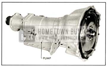
- Test Oil Pressures in Hydraulic Control System. See Figure 5-221.
When diagnosing almost all cases of improper operation it is necessary to have accurate knowledge of oil pressures in the hydraulic control system. These pressure tests should be made before performing an y mechanical work. See Paragraph 5-34 and Figure 5-221.
- Check Engine and Transmission Mountings. Check the engine and transmission mounting bolts and condition of the rubber mountings. Also check for any marks on transmission case or oil pan that would indicate that these parts had been damaged by some obstruction, which might affect alignment of the 1959 Buick Triple Turbine transmission.
5-33 1959 BUICK TRIPLE TURBINE TRANSMISSION TROUBLE DIAGNOSIS
With the results of test and inspection recorded, causes of 1959 Buick Triple Turbine operational faults can be determined from the suggestions below and in Paragraph 5-34.
- Car will not move in any range-rear wheels free.
- Linkage incorrectly adjusted.
- Low or no front pump pressure due to:
- (a) Low oil level.
- Oil screen clogged.
- Worn or scored front pump and/or reaction flange.
- Case and /or valve body gaskets not sealing and allowing air to enter hydraulic circuits.
- Pressure regulator valve binding and hung up.
- Car will not move in forward range only.
- Forward and neutral clutches not operating.
- Rear sprag and neutral clutch not operating.
- Reverse clutch stuck in applied position.
- Car will not move in reverse range only.
- Reverse clutch not operating.
- Forward clutch stuck in applied position.
- Grade retard clutch stuck in applied position.
- Front sprag slipping.
- No grade retard operation only.
- Grade retard clutch not operating.
- Will not shift into G detent position be- cause of binding in parking pawl slide and roller.
- Excess slippage in forward and reverse.
- Low oil level.
- Linkage not properly adjusted.
- Forward and neutral clutches slipping.
- Low front pump pressure.
- Front sprag slipping.
- Front sprag and /or rear sprag slipping.
- Stator control linkage not properly adjusted.
- Converter anti leak down valve not operating properly or missing.
- Pressure regulator valve stuck in by-pass position.
- Excess slippage at high throttle and no top speed in forward.
- Neutral clutch not applying.
- Neutral clutches slipping.
- Stator control linkage not properly adjusted.
- Car creeps forward in neutral.
- Linkage not properly adjusted.
- Neutral clutch and /or forward clutch not releasing or not assembled properly.
- Grade retard clutch not releasing or not assembled properly.
- Car will not hold in park or will not go in park.
- Linkage not properly adjusted.
- Parking pawl slide and roller binding.
- Parking pawl broken.
- Grade retard backing plate retainer ring not in groove or missing.
- Forward clutch does not operate properly.
- Low or no apply pressure due to:
- Valve body and /or case gaskets not sealing.
- O-rings on adapter sleeve damaged or missing.
- Piston outer seal and /or inner oil ring damaged or missing.
- Porous output shaft support.
- Modulator valve and /or limit valve hanging up due to burrs, dirt, etc.
- Neutral clutch apply circuit has excessive leak.
- Piston and /or output shaft support damaged or burred causing piston not to apply or release.
- Piston outer seal lip turned over causing piston to hang.
- Clutch plates warped or worn.
- Clutch plates not properly installed.
- Low or no apply pressure due to:
- Neutral clutch does not operate properly.
- Low or no apply pressure due to:
- Valve body and /or case gaskets not sealing.
- O-rings on adapter sleeve damaged or missing.
- The two rear oil rings on the grade retard reaction shaft damaged or missing.
- The two front oil rings on the output shaft damaged or missing.
- Any one of, or all of first turbine shaft oil rings damaged or missing.
- Piston outer seal and /or inner seal damaged or missing.
- Forward clutch apply circuit has excessive leak.
- Piston and /or front carrier damaged or burred causing piston not to apply or release.
- Piston outer seal lip turned over causing piston to hang.
- Clutch plates warped or worn.
- Clutch backing plate retaining ring not properly installed or missing.
- Low or no apply pressure due to:
- Reverse clutch does not operate properly.
- Low or no apply pressure due to:
- Valve body and /or case gaskets not sealing.
- Porous apply channel in case.
- Reaction flange gasket not sealing.
- Reaction flange and/or case mating surfaces irregular.
- Piston outer seal and/or inner seal damaged or missing.
- Piston and /or reaction flange damaged causing piston to hang.
- Piston outer seal lip turned over causing piston to hang.
- Clutch plates warped or worn.
- Clutch plates not properly installed.
- Clutch pressure plate not properly installed.
- Low or no apply pressure due to:
- Grade retard clutch does not operate properly.
- Low or no apply pressure due to:
- Valve body and /or case gaskets not sealing.
- Adapter sleeve O-rings damaged or missing.
- Piston outer seal and /or inner seal damaged or missing.
- Porous output shaft support.
- Piston and /or output shaft support damaged causing piston to stick.
- Piston outer seal lip turned over causing piston to stick.
- Clutch backing plate retaining ring not properly installed or missing.
- Clutch plates worn or warped.
- Clutch plates not properly installed.
- Low or no apply pressure due to:
- Stator does not operate properly.
- Linkage not properly adjusted.
- Stator piston control valve stuck due to roughness of rear carrier bore, dirt, etc.
- Low or no apply pressure due to:
- Valve body and /or case gaskets not sealing.
- Porous apply channel in case.
- Reaction flange gasket not sealing.
- Reaction flange and case mating surfaces irregular.
- Second turbine shaft rear oil ring damaged or missing.
- The two front oil rings on second turbine shaft damaged or missing.
- Any one of three oil rings on reaction shaft damaged or missing.
- One or both of the front oil rings on second turbine shaft damaged or missing.
- Stator modulator valve stuck.
- Limit valve stuck.
- Stator piston ring damaged or missing or incorrect ring and gap.
- Stator blades not rotating freely due to:
- Piston stuck in bore or carriers because of burrs, dirt, etc.
- Stator blade ring damaged.
- Stator blades damaged.
- Front and /or rear carrier damaged, dirty, etc.
- Stator piston retaining ring improperly installed or missing.
- Stator piston control valve not gauged properly or shims below spring not laying flat in bore.
- Stator piston control valve retainer not in proper position or missing.
- Stator free wheel rollers not properly installed or roller spring damaged or missing.
1959 Buick Oil Pressure check Location, right side
1959 Buick Oil Pressure check Location, left side
5-34 1959 BUICK TRIPLE TURBINE TRANSMISSION OIL CIRCUITS
The following illustrations and descriptions may prove of value in 1959 Buick Triple Turbine Transmission trouble diagnosis. The important oil circuits are illustrated with all sealing points to enable the service man to locate possible points of leakage which should be examined carefully during disassembly.
For Example:
Trouble-Forward Clutch Slips.
Possible points of leakage-(1) Valve body gaskets, (2) Output shaft support adapter sleeves and O-rings, (3) Forward clutch piston inner seal, ( 4) Forward clutch piston outer seal.
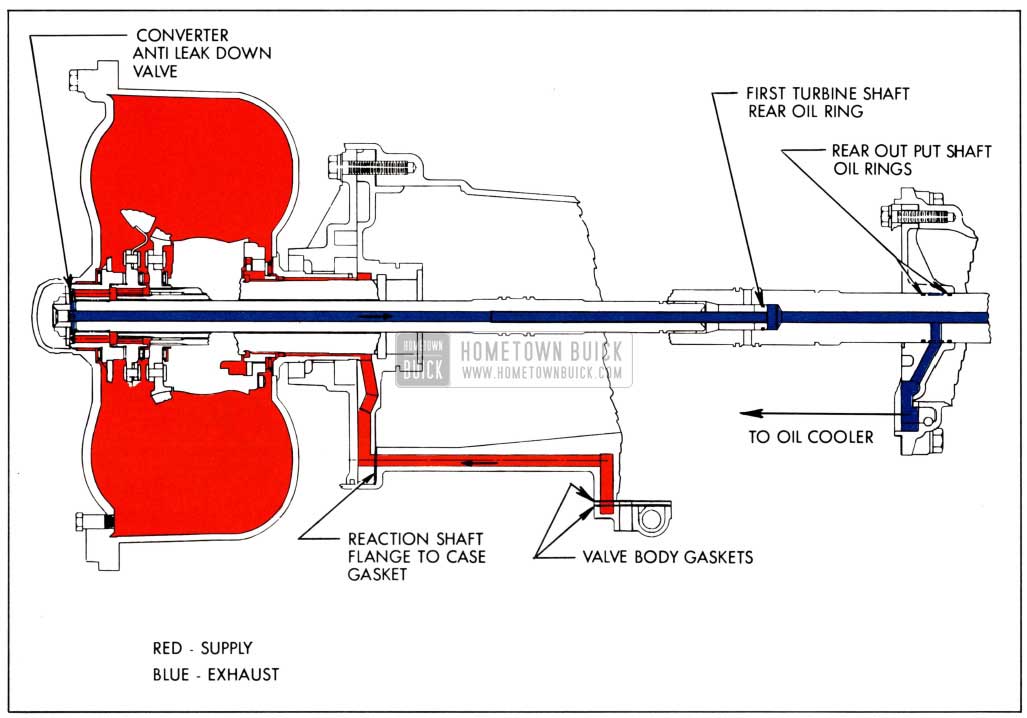
1959 Buick Triple Turbine Oil Circuit through Converter to Oil Cooler
Oil at line pressure leaves an exit port of the pressure regulator valve between the first and second lands, passes through the valve body plate and gaskets to the case. Drilled passages in the case carry the oil forward through the reaction flange gasket to the reaction flange. A cast channel and drilled hole in the reaction flange conduct the oil to a counter bored recess in the reaction flange behind the front pump driving lugs of the converter pump. The oil flows inside the converter pump hub between the hub and stator reaction shaft, through the Flight Pitch stator needle thrust bearing and stator free wheel pilot bearing, into the converter. Oil flows out of the converter between the second and third turbines, forward through drilled holes in the third turbine hub and first turbine disk hub to a counter bored recess in the first turbine disk hub where it is retained by a spring loaded converter anti-leak down valve. Upon sufficient build up of converter charging pressure, the valve is tipped off its seat. The oil then flows through drilled holes in the first turbine shaft; thence rearward the length of the first turbine shaft into the first turbine shaft tube which extends into the output shaft. An oil ring on the first turbine shaft tube plug prevents leak back. Thus the oil is directed through the output shaft to a hole between the two rear output shaft oil rings where it exits through the converter oil transfer flange to the rear bearing retainer line to oil cooler.
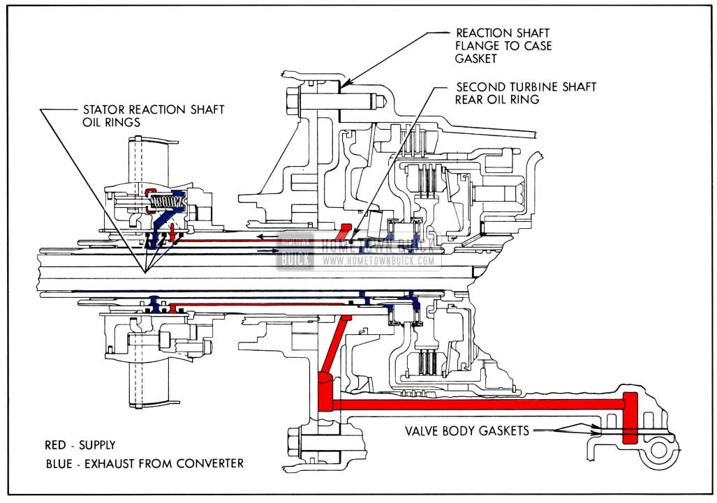
1959 Buick Triple Turbine Stator Valve Oil Supply and Exhaust
- Oil at modulated pressure to the stator piston control valve leaves the valve at an exit port between the first and second lands, passes through the valve body plate and both gaskets to the case where drilled passages conduct it through the reaction shaft flange gasket to the reaction shaft flange. Cast and drilled passages in the reaction shaft flange carry the oil to an undercut in the flange which allows the oil to flow through a drilled hole in the reaction shaft to the space between the reaction shaft and the second turbine shaft. The rearmost oil ring on the second turbine shaft prevents the oil from flowing to the rear, so the oil is directed forward to the center oil ring of the second turbine shaft. Just rearward of the center second turbine shaft oil ring a drilled hole in the reaction shaft allows passage to a groove cut in the O.D. of the reaction shaft between the center and rear oil rings. The oil then flows through the rear slot in the stator rear carrier sleeve through a drilled hole in the stator rear carrier to the cavity formed by the stator piston control valve shoulder and the stator rear carrier.
- Exhaust oil through the center of the stator piston control valve leaves the stator rear carrier through a drilled hole connected to the front slot in the stator rear carrier sleeve. From the sleeve the oil enters a groove in the reaction shaft between the front and center oil rings. A drilled hole through the reaction shaft allows the oil to enter a groove and pass through a hole in the second turbine shaft between the front and center oil rings and occupy the space between the second and third turbine shafts. The oil here lubricates the second turbine to third turbine shaft bushing and also flows rearward to a hole in the third turbine shaft to the space between the first and third turbine shafts. The oil then flows rearward to a second hole in the third turbine shaft forward of the neutral clutch hub and behind the front planet set ring gear hub where it exits to lubricate the caged needle thrust bearing in the neutral clutch hub and other components of the neutral clutch.
PRESSURE TEST SPECIFICATIONS
With engine and 1959 Buick Triple Turbine transmission warmed up:
- Support car in a safe manner with wheels not touching floor and brakes off.
- Connect pressure gauge at point to be checked.
- Connect reliable tachometer to engine.
- Start engine and take pressure reading at specified RPM and stator lever position; stop engine, remove gauge and replace plug.
These pressures should be attained with a correctly functioning 1959 Buick Triple Turbine Transmission.
NOTE: Never drive car on road test with stator linkage disconnected.
1959 Buick Oil Circuit Through Converter to Oil Cooler
1959 Buick Stator Valve Oil Supply and Exhaust
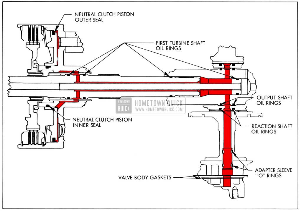
Neutral Clutch Piston Oil Supply
With the selector lever in either Drive “D” range or Reverse “R” range, oil at line pressure leaves the manual control valve, passes through the valve body plate and both gaskets to the case where cast passages direct it through the center oil adapter sleeve and O-rings, to the output shaft support. A drilled hole in the output shaft support directs the oil to a groove and hole in the grade retard reaction shaft between the center and rear oil rings. A groove and hole in the output shaft between the two forward oil rings direct the oil to the space formed by the forward end of the first turbine shaft tube plug and the rear of the first turbine shaft inside the output shaft. The two rear oil rings of the first turbine shaft prevent excessive leakage at this point. The oil then flows forward outside the first turbine shaft tube, between the tube and the first turbine shaft I.D. to a drilled hole in the first turbine shaft where the oil exits to a groove between the two front oil rings of the first turbine shaft. Oil flows from the first turbine shaft groove to a drilled hole and groove in the front planet set carrier to a drilled hole leading to the rear of the neutral clutch piston. Oil is contained in the neutral clutch piston bore by the neutral clutch piston outer and inner rubber seal.
1959 Buick Neutral Clutch Oil Supply
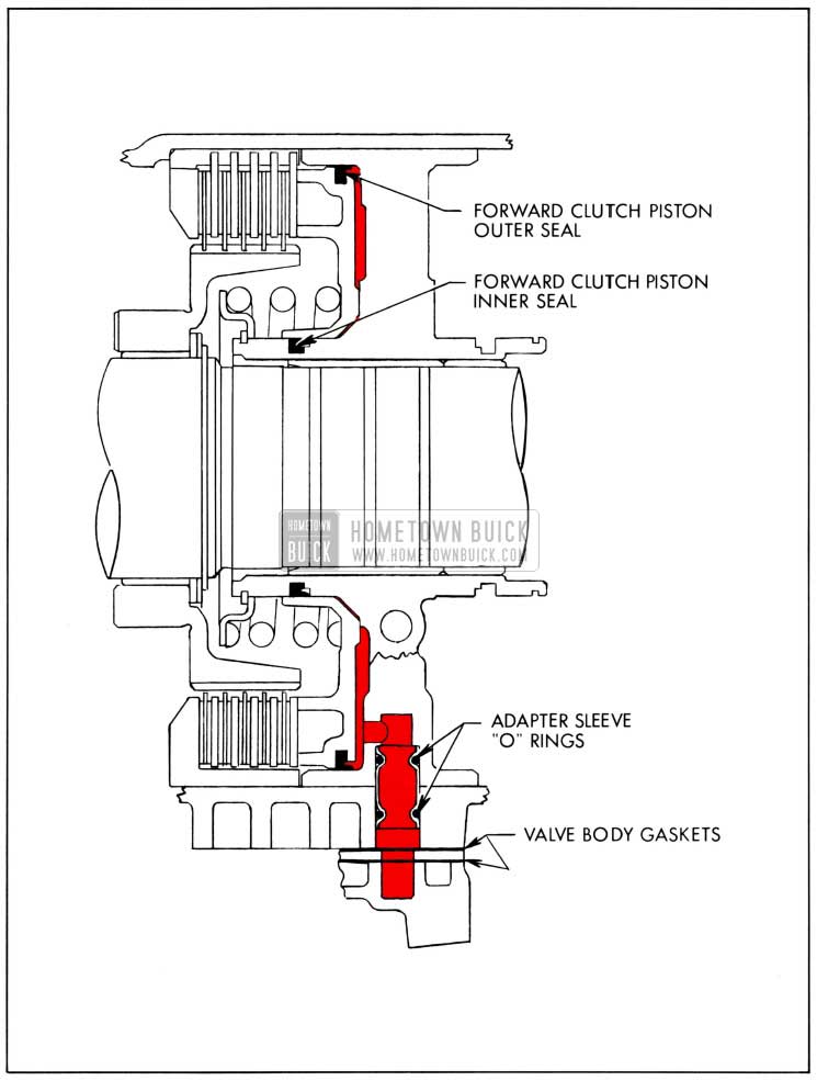
Forward Clutch Piston Oil Supply
With the selector lever in Drive “D” range, oil to the forward clutch piston leaves the control valve at an exit port between the fourth and fifth lands, passes the valve body plate and both gaskets to enter the case. The oil then passes through an adapter sleeve and O-rings. (Left hand adapter sleeve of the three removed through the valve body portion of the case with the 1959 Buick Triple Turbine transmission upside down and viewed from the rear.) Leaving the adapter sleeve the oil enters the output shaft support and flows forward through a drilled hole to bear on the forward clutch piston. The oil is contained in this area by the forward clutch piston inner and outer rubber seals.
1959 Buick Forward Clutch Piston Oil Supply
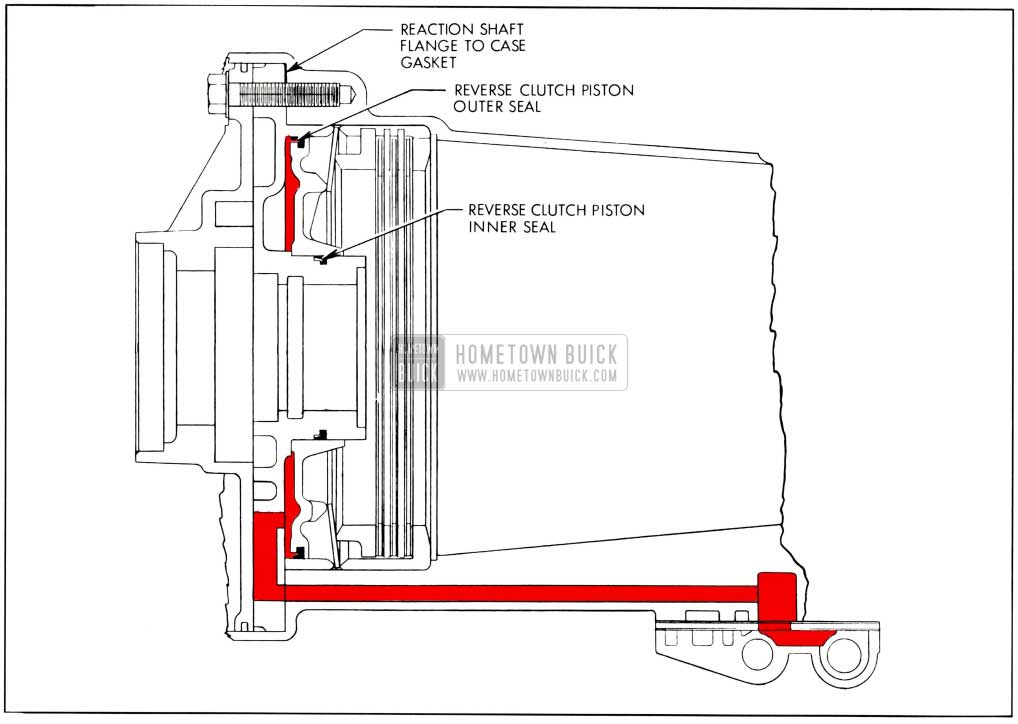
Reverse Clutch Piston Oil Supply
With the selector lever in Reverse “R” range, oil leaves the manual control valve at an exit port between the first and second lands, passes through the valve body plate and both gaskets to the case where a drilled passage conducts it forward, through the reaction shaft flange gasket to the reaction shaft flange. A drilled hole in the rear of the reaction shaft flange allows the oil to enter the cavity in the rear of the reaction shaft flange and bear on the reverse clutch piston. Oil is contained in this area by the reverse clutch piston inner and outer rubber seals.
1959 Buick Reverse Clutch Piston Oil Supply
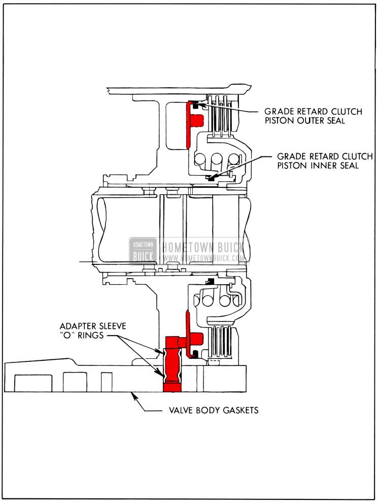
Grade Retard Clutch Piston Oil Supply
With the selector lever in Grade Retard “G” range, oil leaves the manual control valve at an exit port between the first and second lands, passes through the valve body plate and both gaskets to enter the case. The oil then passes through an adapter sleeve and O-rings. (The right hand adapter of the three removed from the valve body section of the case with the 1959 Buick Triple Turbine transmission upside down and viewed from the rear.) Leaving the adapter sleeve the oil enters the output shaft support and flows to the rear through a drilled hole to bear on the grade retard piston. Oil is contained in this area by the grade retard clutch piston inner and outer rubber seals.
1959 Buick Grade Retard Clutch Piston Oil Supply
5-35 1959 BUICK TRIPLE TURBINE TRANSMISSION LINKAGE ADJUSTMENT
Shift Control Adjustment
If a 1959 Buick Triple Turbine transmission does not shift properly, the shift control linkage adjustment may easily be checked as follows:
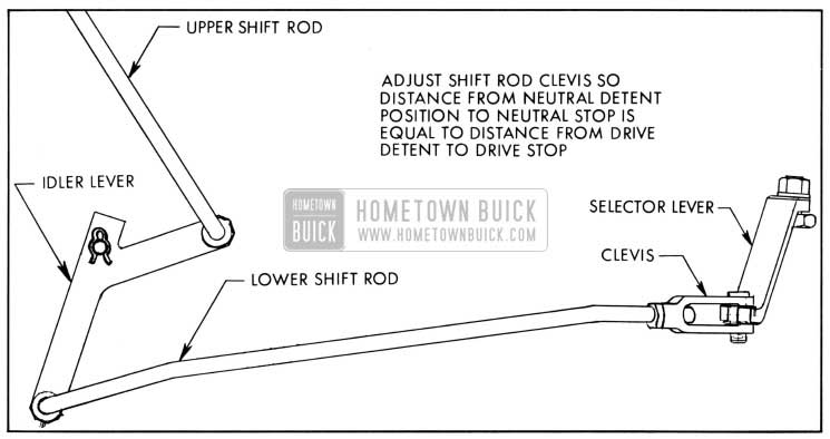
1959 Buick Shift Control Adjustment
- Move manual control lever carefully until 1959 Buick Triple Turbine transmission is shifted into its Drive detent position (manual lever will seem to seat).
- Move manual control lever toward Grade Retard (without lifting toward steering wheel) and note how far it moves before contacting stop.
- Move manual control lever until transmission is in Neutral “N” detent position.
- Move manual control lever toward Reverse and note how far it moves before it contacts stop.
- If movement from Drive detent to stop is the same as movement from Neutral detent to stop, shift control linkage is correctly adjusted.
If above check shows linkage to be incorrectly adjusted, adjust linkage as follows:
- With manual control lever in Drive, raise car to gain access to linkage adjusting clevis on lower shift rod.
- Loosen clevis lock nut. Remove cotter pin, clevis pin and spring washer.
- Lengthen or shorten lower shift rod by turning clevis until distance between Drive detent and stop is equal to distance between Neutral detent and stop.
NOTE: If external linkage has been checked and adjusted properly and 1959 Buick Triple Turbine transmission still doe s not shift correctly; oil pan must be removed and internal adjustments made.
1959 Buick Triple Turbine Stator Linkage Adjustment
- With throttle in wide open position, adjust length of upper stator rod so ball joint stud at forward end will just slip freely in stator lever hole with stator rod held forward to stop and lever held rearward against pickup.
- Lengthen stator rod one turn to allow wide open throttle operation and provide an easy check for correct stator linkage adjustment. (Slight shake or free movement at wide open throttle.)
- Connect ball joint to stator lever and tighten lock nut.
Stator Operation Check
Following is a quick check to determine whether or not the stator blades are making a full shift from low to high angle.
- Have engine and transmission warmed up and stator linkage properly adjusted.
- Connect a reliable tachometer and start engine in “Park” range.
- Set engine speed at exactly 1500 RPM (High step of fast idle cam).
- Block wheels. Have helper firmly apply brakes and shift 1959 Buick Triple Turbine transmission to Drive range. Engine speed should decrease to 1000 RPM plus or minus 60 RPM. If engine speed does not decrease sufficiently, the stator blades are in high angle position, or not fully in low angle position. If engine speed decreases to 1000 RPM, the stator blades are in low angle.
- Move stator lever on carburetor forward to stator high angle position without disturbing throttle setting. In a few seconds, engine speed should increase approximately 150 RPM. If engine speed does not increase approximately 150 RPM, it is an indication that blades are not shifting fully to high angle position. If engine speed increases 150 RPM or more the stator blades are making a full shift from low to high angle.
1959 Buick Triple Turbine ransmission Control Dial Pointer Adjustment
If the control dial pointer does not line up with the letters on the dial face, after checking the shift control linkage adjustment as described in subparagraph c above, adjust dial pointer as follows:
- Shift manual control to Drive position.
- Remove steering column lower housing.
- Access hole in mast jacket allows loosening and adjustment of spring loaded cable clamp to properly position dial pointer. Pointer should be adjusted in Drive “D” range.
- Retighten clamp screw, check pointer position and reinstall steering column lower housing.
Leave A Comment
You must be logged in to post a comment.