SECTION 11-A 1959 BUICK RADIO
11-1 1959 BUICK RADIO DESCRIPTION AND OPERATING INSTRUCTIONS
Description
Three different 1959 Buick radios are available as optional equipment – the 1959 Buick Sonomatic, the 1959 Buick Wonderbar, and the 1959 Buick Transistor Portable combination car and pocket radio.
1959 Buick Transistor Portable Unit
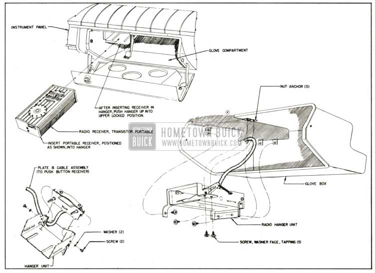
The 1959 Buick Transistor Portable radio is a 2 piece unit consisting of 1 unit permanently installed in the instrument panel, and a portable unit which plugs into a retractable rack in the glove compartment.
The permanently installed unit in the dash is not a complete radio, and will not function until the portable unit is installed in its carrying rack. When the 1959 Buick portable radio is installed, the permanent unit is connected to handle the circuitry to the car battery, antenna and speaker and to handle the tuning of the 1959 Buick radio while the portable unit assumes an assisting function. The permanent unit contains 2 additional transistors to boost performance and to give instantaneous sound delivery.
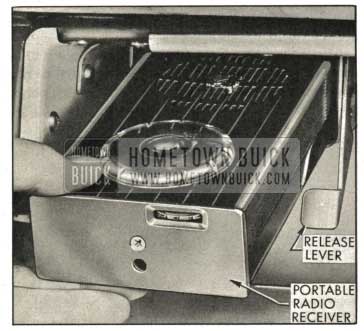
To remove the portable unit from its hanger, the tang on the linkage within the glove compartment should be depressed, and the portable unit will drop downward allowing removal. See Figure 11-2.
1959 Buick Removal of Portable Transistor Unit
The portable unit, when removed from the glove compartment, is a complete radio within itself utilizing 6 separate transistors and 4 mercury cell batteries.
On the end of the portable unit is the On-Off switch and volume control while on the face of the unit is the manual controlled station selector.
The instrument panel portion or permanent unit of the receiver looks, and performs like the Sonomatic push-button rec iver, except that it plays the instant it is turned on. Since the portable unit can be locked in the glove compartment, out of sight, theft is discouraged.
The 1959 Buick Sonomatic and Wonderbar radio installation consists of a receiver with separate speaker mounted at the center of the instrument panel. All 3 radios use the sectional antenna mounted on left front fender, and suppression parts installed at various locations to eliminate interference. The 1959 Buick Wonderbar radio installation also includes a foot control switch mounted on the toe panel to left of the brake pedal.
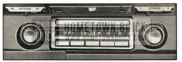
The 1959 Buick Wonderbar, Sonomatic, and the Transistor Portable, when in the car, have five push buttons for push-tuning of five pre-selected stations. In addition to the push buttons, a control knob permits manual selection of other stations.
The 1959 Buick Wonderbar radio receiver also contains an automatic signal-seeking tuner by which the operator can change stations by merely depressing the single selector bar on the receiver, or the foot control switch on the toe panel. The seeking operation is a uni-directional sweep of the broadcast band from low to high frequency with instantaneous return. The tuning mechanism is driven by a spring loaded mechanical motor which is stopped on station by a triggering circuit actuated by voltage developed from an incoming signal. The number of stations on which the tuner will stop can be regulated by use of the sensitivity control knob on the receiver.
A manual antenna which must be extended and retracted by hand is standard equipment. An electrically operated antenna is available as optional equipment. In the latter antenna, a motor drives a nylon tape attached to the upper section of the antenna. A 3-position slide switch on lower edge of instrument panel roll controls the motor, which will run in either direction. Pushing the switch handle to the right raises the antenna and pushing handle to the left lowers the antenna. When the handle is released the switch returns to center “Off” position.
CAUTION: Never attempt to force an electric antenna up or down by hand. This will cause permanent damage to the operating mechanism.
1959 Buick Switch, Volume, and Tone Control Operation
The engine can be started with the 1959 Buick radio on, because of the addition of the audio-power transistor which eliminates the need for a vibrator.
Clockwise rotation of the switch knob, to left of dial, turns the 1959 Buick radio on, and further rotation increases the volume.
High fidelity (true tone) is provided when the tone control knob, behind the switch knob, is at the mid position of the tone control range. A detent in the circuit provides a method of quick location of this position. Rotation clockwise of the tone control knob will diminish bass speaker response. Rotation counterclockwise will diminish treble speaker response.
The 1959 Buick rear seat speaker may be optionally installed at the factory or by the dealer. On the 1959 Buick 4700 & 4800 series the assembly will be concealed beneath the package shelf and the bezel will be eliminated.
When 1959 Buick rear seat speaker is installed, a separate sliding speaker control is mounted on the under side of the upper instrument panel roll.
The right position of the control turns on the rear speaker only, the midway position blends front and rear speakers together in any desired ratio, and the left position turns on the front speaker only. After the volume has been set by the 1959 Buick radio volume control, it will remain constant regardless of the position of the rear seat speaker control.
Push Button Tuning Operation 1959 Buick Wonderbar or Sonomatic
To tune in the station for which the push button is set simply push the button in as far as possible. The button will move easily at start, then a slightly harder push is required to complete the travel. At end of button travel the tuner will rest at the station for which the button has previously been set as described in paragraph 11-5 (b).
Selective Tuning Operation 1959 Buick Wonderbar Radio
NOTE: To insure adequate sensitivity for selective tuning of the 1959 Buick Wonderbar radio it is be st to have antenna extended at least half way.
With the 1959 Buick radio turned on, selective tuning of available stations is accomplished by depressing either the selector bar above the dial (fig. 11-3), or the foot control switch on toe panel to left of the brake pedal.
1959 Buick Receiver Controls-Wonderbar Radio
When the bar or switch is fully depressed and released the tuner will automatically move to the right and stop, accurately tuned, when it reaches the next station having adequate strength to stop it. The tuner will stop at a station having adequate strength even though the volume control is not turned up high enough for the station to be audible.
When the 1959 Buick tuner reaches the right end of the dial it flies back to the left end and again starts moving to the right until it reaches a station having sufficient strength to stop it. By holding the selector bar or foot control switch down, unwanted stations or areas of the dial can be quickly passed over.
The number of stations on which the tuner will stop in selective tuning is regulated by manual setting of the sensitivity control knob, which is located behind the manual tuning knob to right of the dial. See figure 11-3. This is a step control having three positions. This control is in the circuit only while the tuner is seeking and does not affect the “on station” sensitivity of the receiver.
Turning the sensitivity control knob clockwise, in the direction marked “MORE,” increases the number of stations that can be received. Turning knob counterclockwise, in direction marked “LESS,” decreases the number of stations by eliminating those having weak signal strength in the area where car is located. In the extreme “LESS” position of control knob the tuner usually will stop on the strong local stations only.
If the 1959 Buick Wonderbar tuner is operated in certain localities or around buildings where a strong signal is not available, the tuner will automatically search the band from one end to the other without stopping. The sensitivity control knob should be turned clockwise to include more stations, and the antenna should be fully extended when this condition is encountered.
Manual Tuning Operation
The instrument panel manual tuning knob is to right of the dial. See figure 11-3.
On the 1959 Buick Sonomatic radio, this knob may be used to tune in stations other than those for which the push buttons are set; it is also used when tuning to set the buttons for selected stations. On the 1959 Buick Wonderbar radio, the tuning . knob may also be used to tune in stations that are too weak to stop the electronic tuning mechanism.
The 1959 Buick Transistor Portable model uses the instrument panel tuning controls when both units are connected, but the portable unit uses its own tuning dial when removed from the car.
To obtain the best reception with the portable unit removed from the car, rotate the unit until the reception is at its best.
When tuning manually, and particularly when setting up a station on one of the push buttons, careful adjustment of the tuning knob is essential to good radio reception.
On push button selection, if the program sounds screechy or distorted, it is probably caused by improper tuning and can be corrected by adjusting the tuning knob slightly. Since the low notes are apparently more affected by tuning than the high ones, it is a good plan to tune the set to a point where the low notes are heard best and high notes are clear but not screechy. This point may be most readily found by listening to the background noise and tuning for the lowest volume and pitch of this noise. Turning the control knob back and forth until the station is almost lost on either side will enable the operator to hear the difference in reception and select the intermediate position giving best results.
11-2 1959 BUICK RADIO TROUBLE DIAGNOSIS ON CAR
The trouble diagnosis information in this paragraph is of a non-technical nature. It is intended as an aid in locating minor faults which can be corrected without a specialized knowledge of 1959 Buick radio and without special 1959 Buick radio test equipment. If the suggestions given here do not affect a correction, further testing should be done only by a trained radio technician having proper test equipment.
1959 Buick Radio Is Inoperative or “Dead”
- Turn on the 1959 Buick radio. The dial should light and a popping noise should be heard in the speaker.
- If dial does not light, check the fuse located in fuse block. If fuse is okay check 1959 Buick radio lead cable for proper connection to fuse block. Check cable for open circuit. If source of trouble has not been found, remove receiver for test by a trained radio technician.
- If fuse and tubes are satisfactory, substitute a test antenna consisting of a piece of wire about 10 feet long connected to a standard antenna lead-in cable. Place test antenna outside and away from the car. If 1959 Buick radio operates near normal with substitute antenna, some part of car antenna or lead-in is at fault.
- Lead-in wire may be checked for “grounds” by removing lead-in cable connector from 1959 Buick radio receiver and checking with an ohmmeter from connector tip to car body. This check should show an entirely “open” circuit. CAUTION: Do not check with a lamp or any device drawing current, since the conductor inside loom is only .010″ in diameter and will burn off easily if grounded.
- If source of trouble has not been found remove the receiver and check the tubes (Sonomatic and Wonderbar) by replacing one at a time until the bad one is located, or test the tubes with a reliable checker if available.
- If 1959 Buick radio is still inoperative it should be tested by a trained radio technician.
1959 Buick Radio Reception Is Weak
- Fully extend the antenna and turn on 1959 Buick radio. Turn volume control to maximum position and tune across the dial.
- If reception seems just slightly weak, tune in a station having good volume for listening and grasp the antenna rod with your hand. If volume increases adjust the antenna trimmer (par. 11-5). If volume decreases proceed with the following steps.
- Substitute a test antenna as described in subparagraph a, above.
- Open the receiver and check for weak tubes (Sonomatic and Wonderbar) by replacing one at a time until the faulty one is located, or test the tubes with a reliable checker if available. If this does not reveal source of trouble, remove the receiver for test by a trained 1959 Buick radio technician.
1959 Buick Radio Noisy with Car Standing Still
- Close and securely latch hood before checking for noise.
- Start engine, turn on 1959 Buick radio and tune radio to a spot between stations. Engine noise will usually appear in radio as a clicking sound that varies in frequency with speed of engine. If noise is present disconnect antenna lead-in cable from receiver.
- If engine noise stops when antenna is disconnected, check all high tension wires for full seat in sockets of coil and distributor cap.
- Check antenna lead-in cable shield and motor lead shield (electric antenna) for proper ground (par. 11-3) (g).
- If engine noise continues with antenna disconnected, check ignition coil and generator capacitors for clean, tight connections; also check the bond straps between engine and cowl to make sure that there are clean tight connections at both ends. Observe generator armature and brushes; if sparking is excessive, check for open armature.
- If source of noise has not been found, check ignition coil and generator capacitors against known good ones. Ignition oil capacitor lead must be attached to battery terminal of coil. Generator capacitor lead must be connected to “A” terminal of generator. Regulator capacitor must be connected to “BAT” terminal of regulator. All capacitors must have clean metal ground contact.
1959 Buick Radio Noisy with Car Moving at High Speed
- Turn on 1959 Buick radio and check for engine noise as described in subparagraph c above. If engine noise is present, correct as outlined.
- Drive over different types of roads, especially macadam, with 1959 Buick radio on and tuned between stations. Listen for presence of wheel or tire static. In mild form this static shows up as a click in radio that increases with speed; when more severe it shows up as heavy static or a constant roar. The surface of the road determines the strength of static discharge. Wheel or tire static very seldom occurs on dirt or gravel roads.
- If wheel or tire static is present, apply brakes lightly and if noise decreases check front wheels to see that static collectors have been properly installed and make sure that all grease has been wiped off contacts.
- In certain cases of wheel or tire static, the front wheel static collectors alone may not completely eliminate all noise from this source. Static Eliminator Powder, available through G.M.P.D. parts warehouses under Group 9.674, may be used in cases where proper conditioning of static collectors does not remedy tire static. An injector for installing the powder is also available under the same group number. This powder equalizes the electrical charges developed by the tire thus eliminating radio interference difficulties from this source.
1959 Buick Radio Noisy on Rough Road
- Turn on 1959 Buick radio and check for engine noise as described in subparagraph c above. If engine noise is present, correct as outlined.
- Jar the receiver by striking the case with heel of hand, or a rubber mallet. If this produces noisy reception, remove receiver cover and tap each tube with handle of screwdriver until noisy tube is found. Make sure that all tubes are firmly pressed into sockets. If this does not correct the noise, remove receiver for test by a trained radio technician.
- If noisy reception is not produced when receiver is jarred, fully extend antenna and turn 1959 Buick radio volume control on full. If noise appears in speaker check antenna and lead-in wire for loose connections. If movement of lead-in does not cause noise, rap antenna rod with insulated end of screwdriver; if noise then appears, check antenna for shorting to car body or corrosion between antenna sections.
1959 Buick Radio Noisy When Car Equipment is Operated
When excessively loud “clicks” and “pops” are heard in the 1959 Buick radio due to the operation of directional signals, brake lights, power seats or power windows, all ground connections to the 1959 Buick radio antenna and lead-in wire should be thoroughly checked. A poor ground connection at any point can produce the above trouble.
1959 Buick Electric Antenna Operates Improperly
- If operation of 1959 Buick antenna to full up or down position is slower than 8 seconds check for dirty, corroded, or bent antenna sections. Antenna sections must be kept clean and straight and may occasionally be oiled sparingly on surface with a light machine oil.
- If antenna sections are clean and straight and operation is still faulty, check all wiring including ground connections to cowl; also check for defective control switch.
- If cause of faulty operation has not been found, remove antenna and check for defective tube and nylon assembly or defective motor.
1959 Buick Electric Antenna Does Not Operate
- If 1959 Buick antenna fails to operate and motor does not operate as indicated by deflection on charge indicator, then check fuse, all wiring including ground connection to cowl; also check for defective control switch.
- If motor still does not operate, or new fuse blows out, either the motor or its leads are faulty and must be repaired or replaced.
- When motor operates but antenna will not raise or lower, then check for dirty corroded or bent antenna sections.
- If 1959 Buick antenna still fails to operate it will be necessary to remove antenna from car, disassemble for inspection and service.
11-3 1959 BUICK RADIO INSTALLATION INSTRUCTIONS
If 1959 Buick radio parts are removed from car for any reason, the following instructions must be carefully observed to insure proper reinstallation and satisfactory operation. These instructions cover reinstallation only; if an original installation is to be made carefully follow instructions contained in the parts package, particularly with reference to cutting holes in sheet metal and trim.
IMPORTANT: The standard 1959 Buick antenna is matched with the receiver within the range of the trimmer adjustment. Other antennas may not match the receiver within the range of the trimmer adjustment; therefore the use of other than a standard Buick antenna and leadin cable is not recommended.
Installation of 1959 Buick Receiver
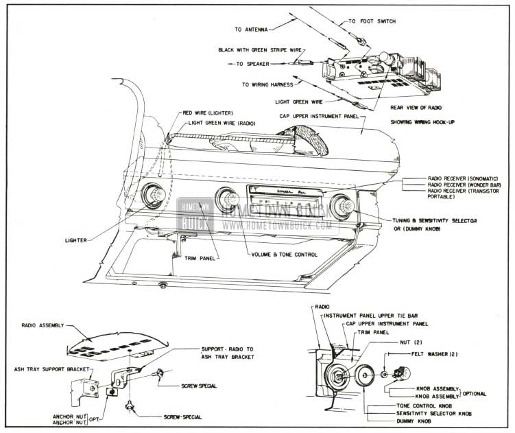
- Remove upper instrument panel ash tray and air conditioning outlet or trim panel.
- Install receiver by sitting in front seat and holding receiver at arm’s length while the two threaded bushings are inserted through control holes in instrument panel. Install and tighten hex nuts on bushings.
- Mount 1959 Buick radio supporting bracket loosely to underside of radio. Align with ash tray supporting bracket and tighten. See figure 11-4.
1959 Buick Receiver Installation
CAUTION: Make sure that spring clips on outer knobs properly engage fiats on control shafts.
- Connect the 1959 Buick radio lead cable to the fuse block. Install proper fuse (par. 10-5, b) in fuse clips and connect radio lead cable to lead at left lower corner of receiver. See figure 11-4.
- If Wonderbar foot control was disconnected or removed, reinstall with cable running up behind steering column pad. Plug cable into receiver and attach it to clip on instrument panel brace. Reconnect antenna battery and speaker wire to receiver.
Make antenna trimmer adjustment and reinstall ash tray, etc.
Installation of Interference Suppression Parts
The capacitor leads are connected to the armature (“A”) terminal of generator and to the “BAT” terminal of regulator. Capacitors must never be connected to the field (“F”) terminal of either unit as this will cause bad pitting of the voltage regulator points, thus preventing it from oper ting properly.
The built-in resistance of each spark plug wire approximates 4,000 ohms per foot.
The coil capacitor is mounted on the coil bracket and the lead is connected to the battery positive ( +) terminal of coil. If capacitor is connected to the distributor negative (-) terminal excessive pitting of distributor contact points will result.
The 1959 Buick Transistor Portable Radio uses a capacitor which is connected to the ignition coil resistor. A static collector is installed in each front wheel hub cup. For good results the cup and the center of steering knuckle spindle must be clean and free from grease. The center of static collector is made of self-lubricating material.
In addition to the items mentioned above, bond straps are connected between the cowl and the rear corners of the engine.
11-4 DISASSEMBLY AND REINSTALLATION OF 1959 BUICK ANTENNA
Disassembly of 1959 Buick Electric Antenna
Before removing 1959 Buick antenna from car, determine whether fault is in the antenna drive or in the switch. This is done as follows:
- Disconnect two leads from switch on instrument panel.
- Connect antenna to a 12 volt D.C. power supply. One lead of the power supply should be grounded to antenna motor case. Touch other lead to each of the terminals on wires that have been disconnected from switch. If antenna does operate, the fault is in the switch.
Disassembly and Procedure for 1959 Buick Antenna Drive
- Remove 1959 Buick antenna from car.
- Remove nut and lockwasher holding cover to drive housing. Remove cover.
- Remove spacer, retaining ring and washers from shaft. (Note the number of washers removed from this side of the reel.)
- Remove the reel by sliding it upward along the shaft.
- Remove any washers found between the reel and the gear and pulley assembly.
- Remove the protective cap on the adjusting screw then remove the adjusting screw and its pressure spring from the side of the drive housing.
- Remove the pressure arm which presses against the gear and pulley assy.
- Remove the 2 screws holding the body tube to the drive housing.
- Pull upward on the body tube until it is free of the drive housing. Connect the antenna motor to a 12 volt power source and raise the antenna to its extreme position. This will leave a minimum amount of nylon wrapped around the gear and pulley assy. Pull the remaining nylon off the gear and pulley assembly and out of the housing.
- Connect the 1959 Buick antenna motor to a 12 volt D.C. power source. Ground 1 lead of the power supply to the motor case. Touch the other lead to the “Up” (red and black striped) wire coming out of the motor case. If the motor shaft rotates and the drive pulley assembly does not rotate, replace the drive pulley assembly.
Another check can be made on the gear and pulley assembly: Remove the gear and pulley assembly from the housing a,nd hold the width of the unit to the light. If light is visible between the 2 welded portions replace the gear and pulley assembly. This test indicates whether excessive pressures have buckled the assembly in manufacture or in use.
Also check the nylon teeth on the assembly for abnormal wear or breakage. Defective teeth are difficult to observe and careful inspection under a strong light is necessary. If any are found, replace the gear and pulley assembly.
If the motor does not rotate, the motor is defective and must be replaced.
To remove the motor, remove the drive pulley assembly. Remove the 2 screws that hold the motor to the drive housing.
Pull the motor and worm gear from the drive housing gently to avoid damage to the oil seal.
Disassembly of the Body Tube
If 1959 Buick radio reception is weak and a loose connection is determined to exist in the antenna, it will be necessary to remove the body and replace the antenna tube and nylon assembly in the following manner:
- Complete the procedure, paragraph 11-4 (b), through step 9, then remove the plate covering the antenna lead-in at the tube.
- Remove the rubber surrounding the end of the wire which protrudes from the tube.
- With a soldering gun, melt the solder at the end of the tip of the wire, and remove the hollow tip.
- Slide the antenna and the attached nylon from the body tube.
Prior to assembly of the motor to drive housing, be sure that the thrust disc and the thrust ball are in place in the drive housing. This is very important. Assemble motor to drive housing and tighten screws. Be sure that there is some end play between the end of motor shaft and thrust ball in housing.
Connect the motor to a 12 volt D.C. power supply. Motor should rotate freely and draw about 4 amps. at 12 volts.
Assembly of the Body Tube
- Slide the new antenna and nylon assembly through the body tube.
- Pull the attached antenna wire through the lead-in opening. Take the hollow tip from the previous antenna and insert it over the wire protruding from the tube.
- Using a soldering gun, solder the hollow tip to the wire securely. See Figure 11-5.
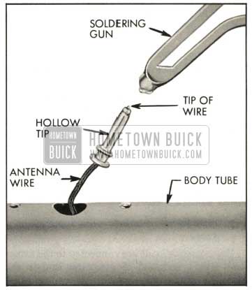
1959 Buick Antenna Wire Soldering
Feed in nylon through hole in drive housing and into drive pulley until about 1 1/4, turns of nylon are in the housing. See Figure 11-6 for proper routing of incoming nylon.
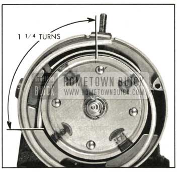
1959 Buick Reinstallation of Nylon In Drive Housing
Assembly of the 1959 Buick Antenna Drive
See fig. 11-7 for correct location of parts necessary for reassembly.
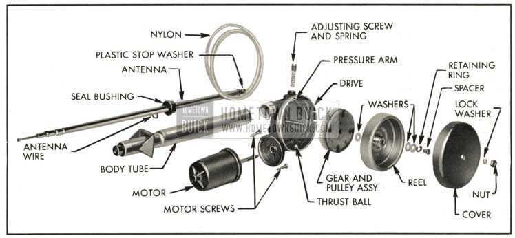
1959 Buick Electric Antenna Disassembled
- Replace the gear and pulley assembly on the shaft.
- Replace the pressure arm.
- Replace the pressure spring and adjusting screw in the side of drive housing. Do not tighten as yet.
- Push the body tube into place on the drive housing making sure that the plastic stop washer is seated against the lower seal bushing in the body tube. Tighten the 2 screws holding the body tube to the drive housing.
- Store the slack nylon in the reel and replace the reel on the shaft. Be certain that the nylon is in the reel and is not caught between the reel and drive housing.
- Replace washers and retaining ring on shaft.
- Tighten adjusting screw until end of screw extends 3/16″ to 1/4″ from point on casting where screw enters. See Figure 11-8.
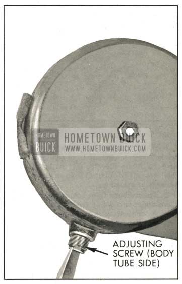
1959 Buick Setting Adjusting Screw
Reinstallation of 1959 Buick Manual Antenna in Car
Figure 11-9 shows all the necessary details for the reinstallation of the 1959 Buick manual operated antenna.
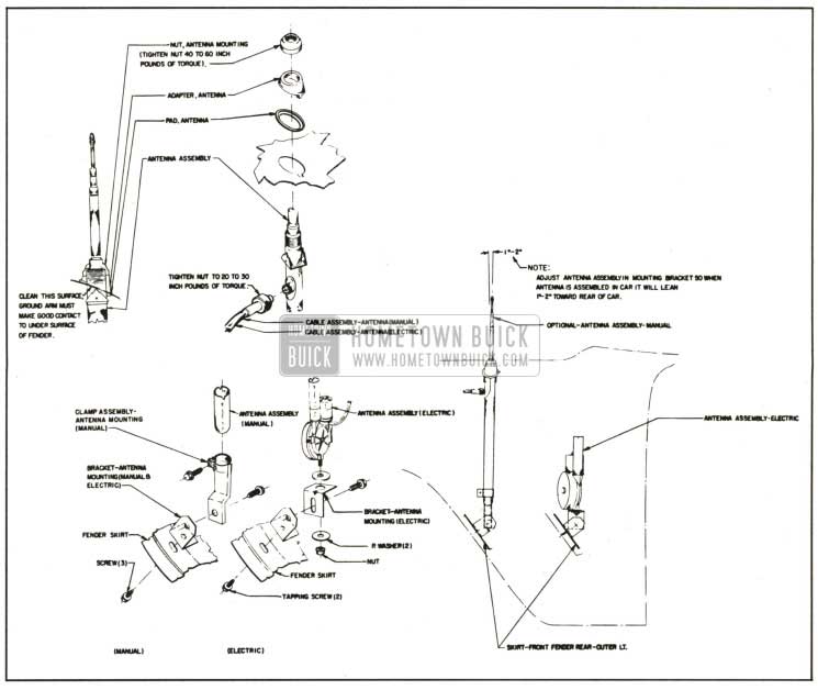
1959 Buick Antenna Installation Details
- When a 1959 Buick antenna is being installed on a fender, make a template from similar fender to properly locate the hole for the body tube. A template may be obtained from an antenna parts package, if available.
- Remove burr from hole cut in fender and clean under surface of fender around hole for good ground contact of antenna.
- Loosely assemble antenna to mounting supporting bracket.
- Connect 1959 Buick antenna lead-in cable to the antenna assembly, tighten securely, then insert antenna assembly through hole from under fender, with antenna lead-in connector pointing toward front of car.
- Place adapter and mounting nut on antenna assembly over pad and tighten nut securely, using Antenna Nut Wrench J 5185-1.
- Fully extend antenna, and adjust mounting support and clamp so that the antenna will lean one to two degrees rearward and one to two degrees inward from vertical. Tighten supports securely. See figure 11-9.
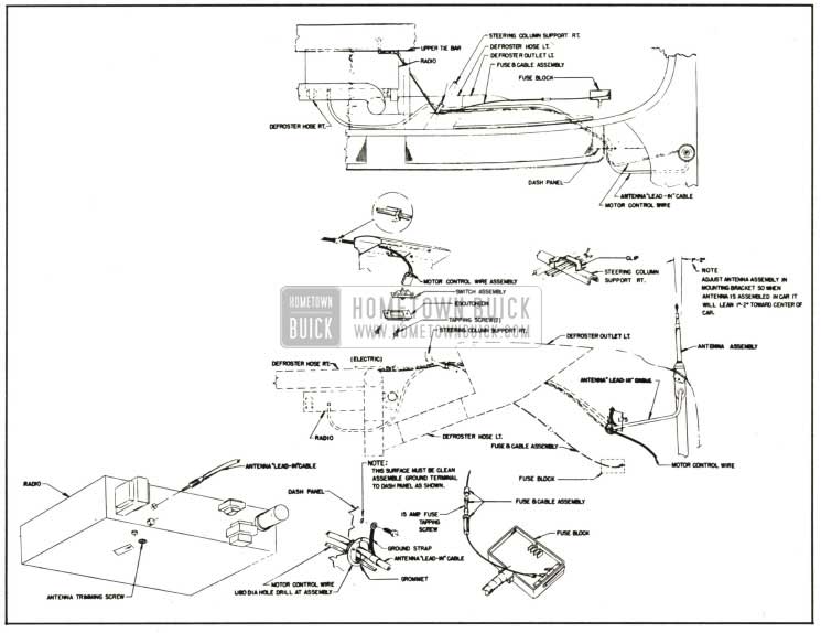
- Remove plug from hole provided in cowl. Install grommet and thread lead-in cable through grommet until ground lead is at body.
- Attach cable ground lead to cowl at hole provided. Be sure to clean paint from cowl surface at this point, then attach the lead terminal with a #10-16 x 1/2″ tapping screw. See Figure 11-10.
- Remove the 1959 Buick instrument panel, upper right and left.
- Route the lead-in cable up and over the left defroster outlet and clip the cable to the steering column right support.
- Route the cable behind and under the right defroster hose.
- Plug the 1959 Buick antenna lead-in wire into the right rear of the receiver.
Installation of 1959 Buick Electric Antenna
Figure 11-10 shows all necessary details for reinstalling the 1959 Buick electric motor driven antenna. The installation procedure is very similar to that described for manual antenna (Subpar. f) except for the following points.
1959 Buick Electric Antenna Installation
- Bring the motor wire through grommet in cowl with the lead-in cable and attach lead-in ground lead to cowl with a 10-16x 1/2″ tapping screw, with internal lockwashers on both sides of terminal. See figure 11-10.
- Remove instrument panel upper right and left. For the routing and the connection of the motor control wire assembly, see Figure 11-10.
- Route the motor control wire up and over the left defroster outlet. Plug the fuse and cable assembly into the motor control wire plastic connector.
- Clip the motor control wire assembly to the steering column support right located under the upper instrument panel center support.
- Fasten the motor control wire to the harness clip on the instrument panel upper tie bar.
- Pull the motor control wire assembly through the holes in the upper tie bar and the front of the instrument panel.
- Plug the motor control wire assembly plastic connector to the antenna switch assembly.
- Insert the antenna switch assembly into the instrument panel with the single terminal of the switch assembly toward the front of the car.
- Assemble the escutcheon and the switch to the instrument panel securely.
- Connect the fuse and cable assembly to the fuse block.
- Check 1959 Buick antenna for travel time from fully retracted to fully extended positions. Time should not exceed 8 seconds. If antenna operates too slow, or is inoperative, refer to paragraph 11-2.
11-5 1959 BUICK RADIO ADJUSTMENTS-ON CAR
When making the adjustments covered in this paragraph it is essential to have the car in a location that is as free as possible from outside inter!erence.
1959 Buick Antenna Trimmer Adjustment
An antenna trimmer adjustment is provided for matching the antenna coil in the receiver to the 1959 Buick antenna. This adjustment must always be made after installation of receiver and antenna, or after any repairs to these units. The adjustment should also be checked whenever the radio reception is unsatisfactory.
- Raise antenna to maximum height.
- Tune 1959 Buick radio to a station between 600 and 1000 K.C. that can barely be heard with volume turned full on.
- Insert a screwdriver up through the opening in the rear of the bottom of the receiver (fig. 11-10). Carefully turn the trimmer screw back and forth until a position is found that gives maximum volume.
Setting Push Buttons to Desired Stations
- Turn on the 1959 Buick radio.
- Pull button all the way out. It is desirable to set up the push buttons in logical sequence. For example, lowest frequency desired station on first button, next higher frequency station on second button, etc.
- Carefully tune in the desired station manually, then push the button all the way in.
- Move dial pointer away from the selected station and push the button to make certain the station will be properly tuned in.
- Turn tuning knob back and forth to make certain that best tuning is obtained with the push button. If best tuning is not obtained, repeat steps 2, 3, 4.
11-6 INSTALLATION OF 1959 BUICK REAR SEAT SPEAKERS
1959 Buick rear seat speakers may be installed on sedans by either the factory or by the dealers. A separate speaker may be mounted on the shelf behind the rear seat, or as on the Model 4867 it can be mounted in the notch of the rear seat back cushion.
A slider speaker control is used to vary the volume of each 1959 Buick speaker. When the control is moved, 1 speaker gradually fades out, while the other speaker becomes louder. At the extremes only 1 speaker can be heard. At midpoint both speakers can be heard equally.
The recommended procedure for installation is given below: For any questions concerning the installation procedure in the front part of the car, see fig. 11-11.
1959 Buick Rear Seat Speaker Control Installation
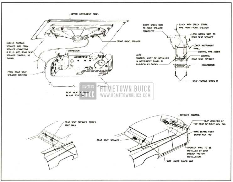
- Remove the plate covering the hole in the instrument panel for the installation of the speaker control. Speaker control is directly above the selector knob of the 1959 Buick radio.
- Remove glove box to enable removal of 2 screws holding right side of center air conditioning outlet.
- Remove remaining 4 screws holding center air conditioning outlet. Remove outlet.
- Remove the 1959 Buick speaker wire from the speaker connector and plug into the rear seat speaker control.
- Connect the green speaker wire to left control terminal, and plug the second control harness wire into the connector in the right side of the 1959 Buick radio.
- Place escutcheon over speaker control and install the unit to the instrument panel with the 2 screws provided.
- Replace the air conditioning center outlet.
- Replace the glove box.
- Route the green speaker wire across the upper portion of the instrument panel and down behind the right kick pad.
- Connect speaker wire to the wire which will run to the rear seat speaker.
- Remove sill plates on right side and run wire rearward under the floor mats approximately 2″ from the edge of the mat. Replace sill plates.
- Remove rear seat cushion and back.
- Remove rear compartment center cardboard panel and remove insulation from under side of package shelf, if used.
- Insert wire under seat cushion, behind the seat back, and over the top edge of the cardboard in the trunk compartment. Make certain that the wire is positioned so it will not be pinched when the cushions are replaced. It may be necessary in some cases to pry a small opening at the floor level for wire clearance. For assembling the rear seat unit, see fig. 11-12.
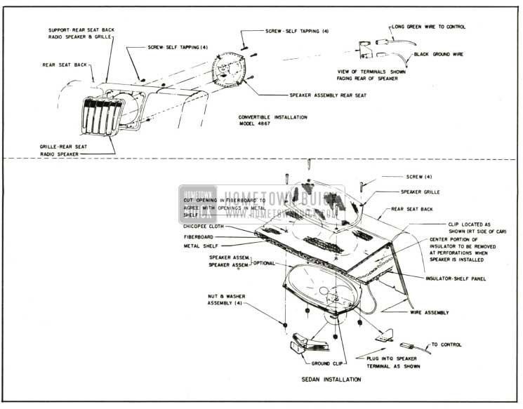
1959 Buick Installation of Rear Seat Speaker
11-7 1959 BUICK BUICK RADIO SCHEMATICS
To help with the servicing of 1959 Buick radios the schematics of each are shown in this section.
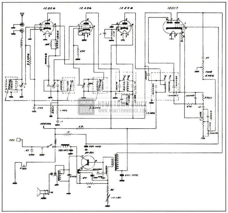
1959 Buick Radio Circuit Schematic-Sonomatic
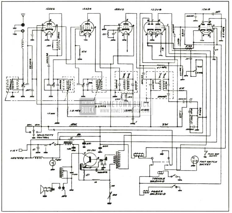
1959 Buick Radio Circuit Schematic-Wonderbar
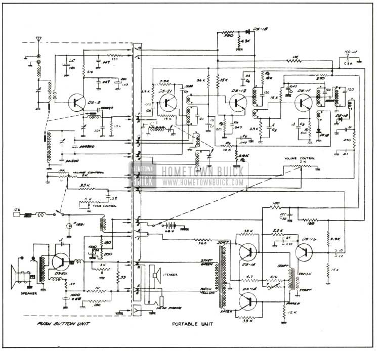
1959 Buick Radio Circuit Schematic-Transistor Model
Leave A Comment
You must be logged in to post a comment.