SECTION 7-A 1959 BUICK CHASSIS SUSPENSION SPECIFICATIONS AND DESCRIPTION
7-1 1959 BUICK CHASSIS SUSPENSION SPECIFICATIONS
Tightening Specifications
Use a reliable torque wrench to tighten the parts listed, to insure proper tightness without straining or distorting parts. These 1959 Buick chassis suspension specifications are for clean and lightly lubricated threads only; dry or dirty threads produce increased friction which prevents accurate measurement of tightness.
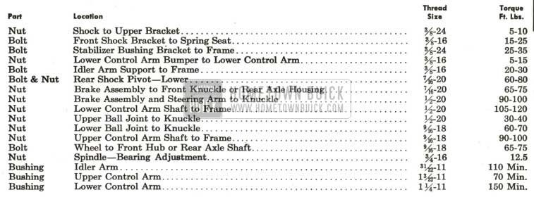
1959 Buick Chassis Tightening Specifications
1959 Buick Wheels and Tires
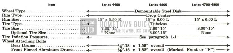
1959 Buick Wheels and Tires Specifications
1959 Buick Shock Absorbers

1959 Buick Shock Absorbers Specifications
1959 Buick Springs
1959 Buick Springs Specifications
Dimensional Specifications
NOTE : Dimensions and limits given in these specifications apply to new parts only. Where limits are given, “T” means tight and “L” means loose.
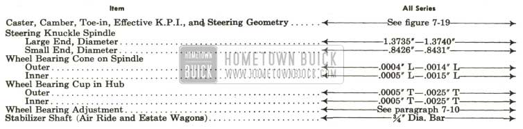
1959 Buick Chassis Dimensional Specifications
7-2 DESCRIPTION OF 1959 BUICK WHEEL SUSPENSION
1959 Buick Front Wheel Suspension
The 1959 Buick front wheel suspension allows each front wheel to rise and fall, due to change in road surface level, without appreciably affecting the opposite wheel.
Each 1959 Buick wheel is independently connected to the frame front cross member by a steering knuckle, ball and socket assemblies, and upper and lower control arm assemblies. See figure 7-1.
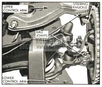
1959 Buick Front Wheel Suspension
The upper and lower arms are so placed and proportioned in length that they allow each knuckle, and wheel to move through a vertical arc only. The front wheels are held in proper relation to each other for steering by means of two tie rods which connect to steering arms on the steering knuckles and to the intermediate rod.
A coil type chassis spring is mounted between the frame front cross member and a spring seat in each lower control arm assembly.
Air Ride equipped 1959 Buicks have low rate front coil springs to match the rear air spring rate. A spring seat spacer between the spring seat and lower control arm accommodates the longer low rate spring.
A large rubber bumper is mounted on the outer end of each lower control arm to limit travel of the arm during compression of chassis spring. A similar rubber bumper is mounted on the frame under each upper control arm to limit travel of arm during rebound of 1959 Buick chassis spring.
Side roll of the front end of chassis (on Air Ride jobs and estate wagons) is controlled by a spring steel stabilizer shaft. The shaft is mounted in rubber bushings supported in brackets attached to lower flange of each frame side rail. The ends of stabilizer shaft are connected to the front sides of lower spring seats by links which have rubber grommets at both ends to provide flexibility at the connections and prevent rattle. See figure 7-7.
The lower control arm assembly consists of two drop forged steel arms solidly riveted to a
CAUTION: Rear shock absorbers on jobs equipped with Air Ride have an extended length which is approximately 1″ shorter than the extended length of standard shock absorbers. Standard rear shock absorbers must not be used on Air Ride jobs as serious damage to the air springs may result.
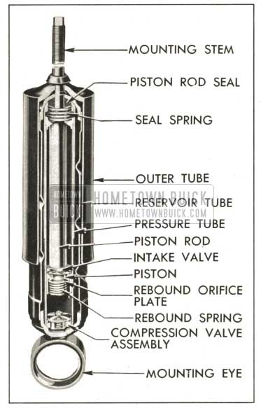
1959 Buick Typical Shock Absorber
1959 Buick Shock Absorber Construction and Operation
The 1959 Buick shock absorber consists of two concentric tubes, a piston and rod, and valves for controlling hydraulic resistance. The rear shock absorber has an additional tube which acts as a stone shield.
The pressure (inner) tube provides a cylinder in which the piston and rod operate. The upper end is sealed by a piston rod seal, and the lower end is closed by the compression valve assembly. This tube is completely filled with fluid at all times. The reservoir tube provides space for reserve fluid and for overflow from the pressure tube during operation.
The piston, piston rod and outer tube are attached to the car frame, while the pressure and reservoir tubes are attached as a unit to the chassis suspension through the lower mounting. As the wheel moves up and down with respect to the frame the 1959 Buick chassis spring compresses or expands, and the shock absorber is telescoped or extended. This action forces the fluid to move between the pressure and reservoir tubes through small restricting orifices in the valves. The relative slowness of fluid movement imposes restraint on the telescoping or extension of the shock absorber, thus providing the required dampening effect on spring action.
- Compression Stroke Operation. When the 1959 Buick chassis spring is being compressed the shock absorber is telescoped, causing the piston to move down in the pressure tube, forcing fluid through holes in the piston. The pressure lifts the intake valve plate, allowing fluid in lower chamber to pass into the upper chamber. As the piston rod moves downward into the pressure tube it occupies space previously filled with fluid and this displaced fluid is forced out of the lower chamber into the reservoir through the restricting orifice in the compression valve. On fast or extreme movements when the fluid flow exceeds the capacity of the orifice, the spring loaded relief valve in the compression valve assembly is forced open to permit more rapid escape of fluid. The amount of compression control is governed entirely by the volume of fluid displaced by the piston rod, and the resistance to chassis spring travel is governed by the area of the orifice and the strength of the compression relief valve spring.
- Rebound Stroke Operation. When the 1959 Buick chassis spring expands, or rebounds, the shock absorber is extended and its resistance is instantly effective. As the piston is pulled upward the intake valve plate seats and fluid in the upper chamber is forced through slots in the plate and holes in the piston to build up pressure against the rebound orifice plate. As the pressure increases, the rebound spring is compressed and the orifice plate leaves its seat to permit fluid to pass into the lower chamber. As the piston rod moves upward out of the pressure tube the space previously occupied by the rod is filled with fluid drawn into the lower chamber from the reservoir. A separate intake valve in the compression valve assembly opens to permit return of this fluid.
Leave A Comment
You must be logged in to post a comment.