GROUP 12 1959 BUICK FRAME AND SHEET METAL
12-1 CHECKING ALIGNMENT OF 1959 BUICK FRAME AND SUSPENSION
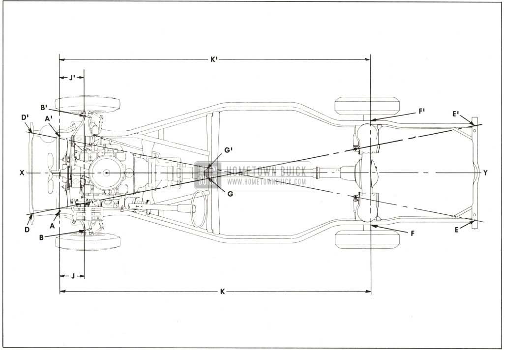
When a 1959 Buick frame has been damaged by accident the following procedure may be used to check alignment of the 1959 Buick frame, and the alignment of the chassis suspension members with the frame. This procedure should also be used to check alignment after repairs to 1959 Buick frame have been completed.
Checks are to be made with 1959 Buick frame assembled with power plant, body, etc. and car resting on wheels. The car should be placed on a clean floor that is reasonably level. Both sides of the front ends of the frame must be the same distance from the floor; the same condition must exist at rear end of frame. Where points are to be extended to floor by use of a plumb bob, it is desirable to attach clean pieces of paper to floor with tacks or tape so that the points can be clearly marked. Apply brakes or block wheels so that car cannot move.
- Using a plumb bob, extend the following points to the floor and mark where point of plum bob touches floor, as shown in figure 12-1.
1959 Buick Checking Alignment of Frame and Suspension
- A and A1 at rear stabilizer bracket to 1959 Buick frame bolts or holes.
- B and B1 at sharp corner at forward edge of lower ball joint plate.
- X at center of bolt hole in center of front spring support cross member (centerline of frame).
- D and D1 at center of corner rivets attaching front cross member to side rails.
- E and E1 at center of corner rivets attaching rear bumper cross member to side rails.
- F and F1 on side rails just rearward of rear axle housing, holding plumb line fiat against side rails.
- G and G1 at each side of torque ball flange.
- Move car out of the way. Using a chalked line, draw lines on the floor through the following points: A and A1, B and B1, F and F1.
- Divide the distance between F and Fl and mark the center point Y on line F-F1. Draw frame centerline through points X and Y.
- Measure diagonal distances D to E1 and D1 to E. If these diagonals are not equal within 3/16″ the 1959 Buick frame is bent.
- Measure the distances J and J1. If these are not equal within 1/4″ a lower control arm is bent.
- Measure the distances K and K1, which will be equal within 3/16″ if rear axle is not bent and is properly aligned with 1959 Buick frame. Points G and Gl should be equally distant from vehicle centerline X-Y. If distances K and K1 are not equal within 3/16″ and points G and G1 are equally distant from centerline, a bent rear axle housing or torque tube is indicated. If points G and Gl are not equally distant from centerline, look for misalignment of engine in the 1959 Buick frame.
12-2 1959 BUICK FRAME REPAIRS
Straightening and Welding
In case of frame distortion resulting from an accident it is permissible to straighten or weld the 1959 Buick frame if the distortion is not excessive.
Heat can be applied without materially weakening the steel, provided this is kept below 1200°F. This is a deep cherry red when viewed in subdued daylight, as in an average shop. Heat in excess of 1200°F. will weaken the metal structure and lead to eventual failure in service.
Replacement of 1959 Buick Frame Members
If a front spring support cross member is very badly distorted as a result of a front end collision, replacement is advisable because its rigid box construction makes proper straightening very difficult. Since the front suspension members are mounted on the front spring cross member, front end alignment will be affected if the cross member is not in perfect alignment.
The front spring support cross member is available for service replacement. The old member may be removed from the 1959 Buick frame by cutting the attaching rivets and welds, after removing other parts or assemblies to allow working space.
When installing a new frame member use hot rivets since they can be properly driven with hand tools. Cold driven rivets are not recommended because they cannot be securely driven with hand riveting tools. In places where hot rivets cannot be installed it is permissible to use finished bolts snugly fitted in reamed holes. Use lockwasher with bolts and draw nuts up tight. Weld a new member to adjacent members in the same manner that the replaced member was welded.
After installation of any new frame member, check the 1959 Buick frame for proper alignment as described in paragraph 12-1. After any repairs or replacements in front end of frame be sure to check front wheel alignment (par. 7-17).
12-3 1959 BUICK BODY MOUNTINGS
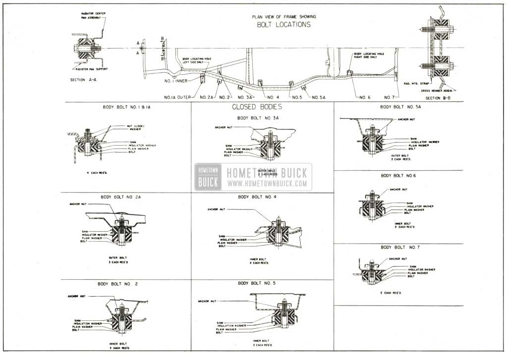
At each closed body mounting point, a rubber shim is placed between the body and the frame bracket and a rubber insulator washer is placed under the 1959 Buick frame bracket. A plain steel washer and a tubular spacer limit compression of the rubber parts to a predetermined amount as the body bolt is tightened. See figure 12-2. This form of mounting eliminates metal-to-metal transmission of road and chassis noise into the body.
1959 Buick Body Mountings-Closed Bodies
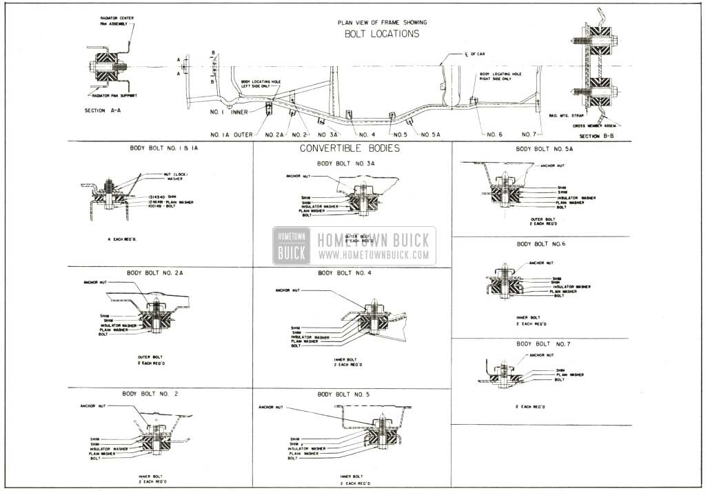
At some convertible body mounting points, a solid composition shim is placed between the body and the frame bracket and a plain steel washer and bolt anchors the body to the 1959 Buick frame. See figure 12-3.
1959 Buick Body Mountings-Convertible Bodies
In addition to the parts shown in figures 12-2 and 3, steel shims are added as required at individual mountings’ to compensate for variations in body and 1959 Buick frame in order to insure a firm mounting without distortion of body. Whenever it becomes necessary to remove body mountings, care must be taken to reinstall all of the mounting parts and steel shims in their exact original positions.
Closed bodies should not be re-shimmed to correct distortion of door openings. These openings should be shaped as required by the use of body jacks. The body should rest firmly on all mountings before bolts are tightened and steel shims should be added where body does not contact a mounting. Shims for this purpose are furnished under group 9.023.
Convertible bodies may be re-shimmed in cases where door locks do not latch securely after door is properly adjusted in body opening. In such cases, shims placed under the ends of body will close in the body door opening sufficiently to insure proper latching of door locks.
When body bolts are tightened use a torque wrench to tighten all bolts uniformly to 25 ft. lbs. torque. The specified torque is very necessary to insure proper compression of convertible body mounting shims, and to insure tightening against the spacers in closed body mountings. Excessive tightening must be avoided as distortion of mountings will result.
12-4 DESCRIPTION OF 1959 BUICK FRONT END SHEET METAL
1959 Buick Front End Sheet Metal Assembly
All 1959 Buick front end sheet metal parts are joined together in an assembly that may be removed and installed as one unit or the separate parts may be replaced.
The front end sheet metal assembly is attached to the 1959 Buick frame and body at adjustment points indicated in Figures 12-4, 12-5 and 12-6.
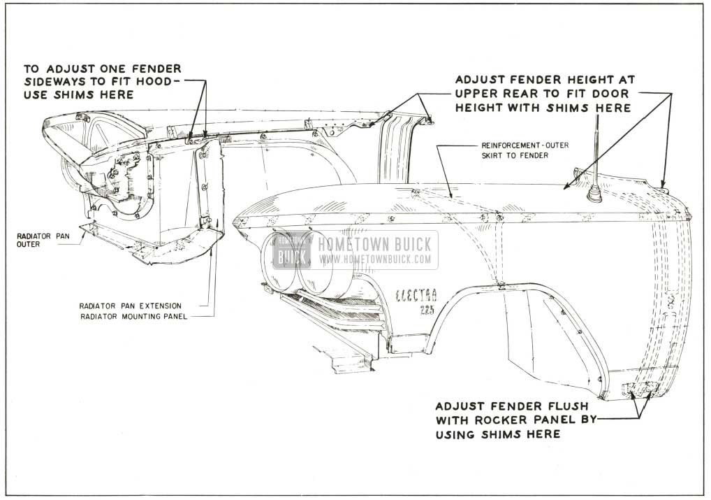
1959 Buick Front Fender Adjustment Points
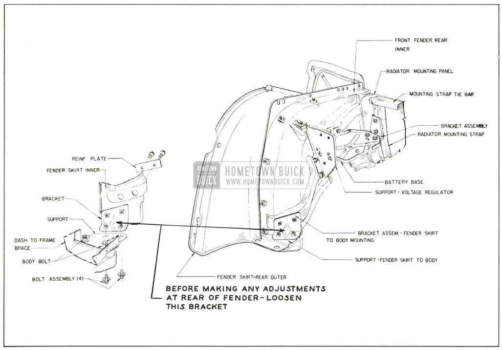
1959 Buick Fender Skirt To Body Bracket
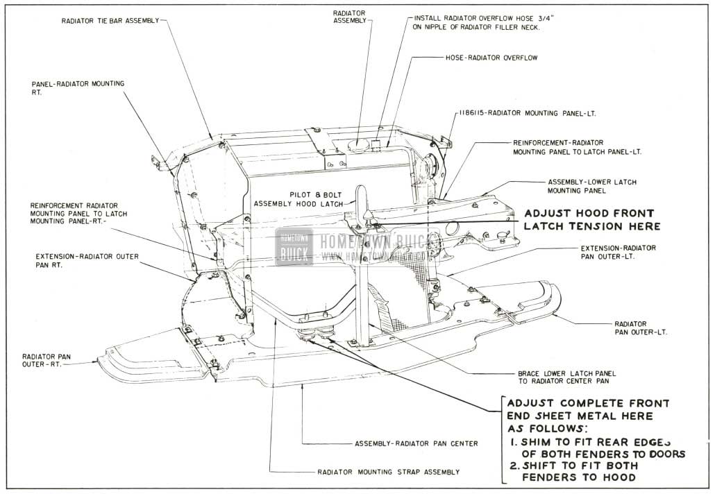
1959 Buick Front End Sheet Metal Adjustment Points
The front of the assembly is supported on the front spring cross member by two body type mounts at the radiator mounting strap.
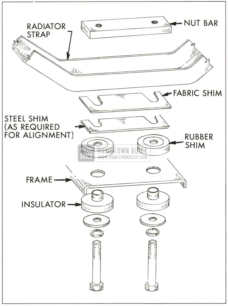
1959 Buick Radiator Strap Mounting
Shims at this location allow up and down movement of the front of the sheet metal assembly. Fore and aft and side adjustment is allowed by oversize holes in the radiator mounting strap. See Figure 12-7. One body type mounting supports the radiator pan assembly at the front frame cross member. The bracket to the cross member has slotted holes to allow up and down adjustement, while oversize holes in the radiator pan allow some adjustment fore and aft and to either side. See Figure 12-8.
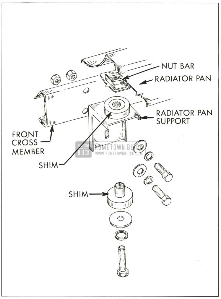
1959 Buick Radiator Pan Mounting
The 1959 Buick rear of the sheet metal assembly is supported on the body cowl at the vertical adjustment points indicated in Figure 12-4. Shims at the four upper rear locations in Figure 12-4 allow vertical adjustment of the rear assembly. The lower rear edge of the assembly is attached to the body at the rocker panel by two bolts on each side. See Figure 12-4. Shims are used at this location to provide in and out adjustment of the lower rear edge of the fender.
1959 Buick Hood, Hinges and Latch Mechanism
The 1959 Buick hood panel is of one piece construction, strengthened and held to shape by front and rear transverse reinforcements of stamped sheet metal.
The rear of the 1959 Buick hood assembly is attached to the body cowl and fender on each sidy hinge assemblies which permit the front of the hood to be raised. A heavy coil spring connected between each hinge assembly assists in raising the hood and holds it in the open position. See Figure 12-9.
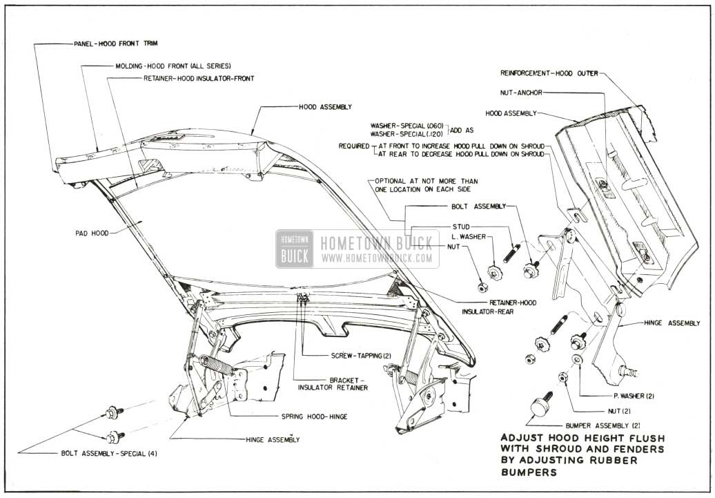
1959 Buick Hood Assembly
The front of the hood is held down by a dovetail bolt on the lower latch mounting panel (Figures 12-6 and 12-10) which engages a latch mechanism in the front of the hood assembly.
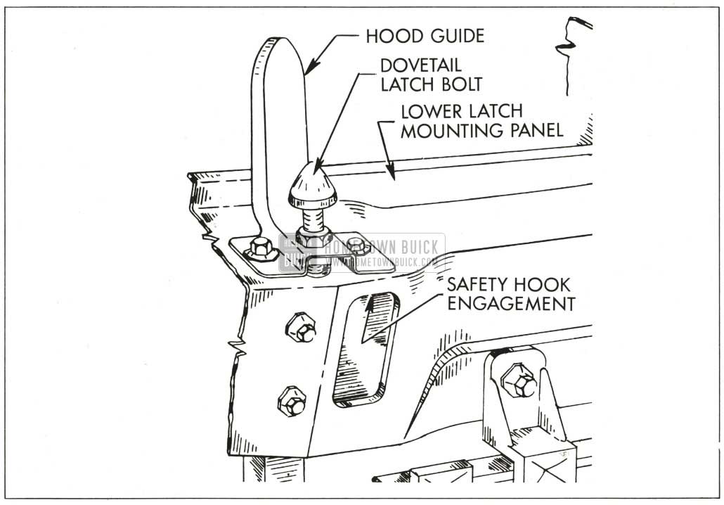
1959 Buick Lower Hood Latch Bolt and Guide
The 1959 Buick hood is unlocked by lifting a release lever located beneath the 1959 Buick hood front moulding and raising the hood at the same time. The single release lever also release a safety hook. The release lever must. be held up until the hood is lifted beyond the catch for the safety hook. See Figure 12-11.
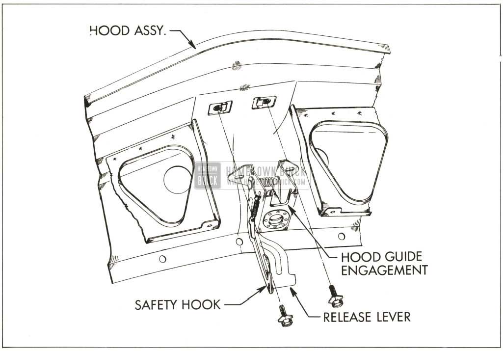
1959 Buick Upper Hood Latch
12-5 1959 BUICK FENDER, BUMPER AND HOOD ALIGNMENT INSPECTION
The 1959 Buick hood, front fenders and bumper must be aligned with each other on every car to take care of slight variations in form and dimensions of the individual parts. Sheet metal parts stamped in a given set of dies will vary somewhat in form and dimensions due to variations in the hardness of different batches of sheet metal, which cause the stampings to spring in varying amounts when released from the form dies.
The 1959 Buick hood and front fenders are properly aligned during the installation at the factory; however, some readjustment may be required after a car has been shipped or has been in service for some time. This is because sheet metal parts may take a different “set” as a result of vibration and shock incident to shipping or operation during the break-in period. In judging the need for readjustment it must be understood that exactly uniform fit and spacing cannot be obtained on all cars of a given model.
1959 Buick Hood Noises or Panel Flutter
Squeaks or grunting noises in the hood when driving over rough roads do not necessarily indicate misalignment of hood and fenders. These noises may be caused by metal contact at some point where clearance should exist or by worn or dry hood bumpers.
If the 1959 Buick hood squeaks, check with 1/16″ thick feeler all around the hood for clearance at fenders and cowl. If an edge of metal is making contact at any point where clearance should exist a bright metal spot will usually be found. Such spots may be depressed by spring hammering to provide clearance.
A grunting noise in the hood is usually caused by dry rubber bumpers or cowl ledge lacing. Lubricate all rubber bumpers on fender rails and cowl with Lubriplate. To correct a persistent case of squeaking or grunting where hood top panel contacts ledge lacing, even when lubricated, cement a %6″ thick strip of felt to panel where the lacing makes contact.
To prevent hood panel flutter, the rear end of hood panel must have firm contact with the rubber bumpers and lacing attached to cowl ledge. The hood may be raised or lowered by adjustment at hinges. See figure 12-9.
Preliminary Tightening
Before deciding upon any adjustment to correct hood or fender misalignment it is advisable to check tightness of all attaching screws and bolts, since a true picture of correction requirements cannot be obtained when the sheet metal is loose and free to shift.
After all parts are properly tightened inspect fender and hood alignment (subpar. c) and hood alignment (subpar. d). Make all inspections before performing any adjustments because an adjustment at one point will usually alter alignment at other points. The preliminary inspection should determine the adjustments that will produce the best overall alignment of hood and fenders at all points.
1959 Buick Fender and Hood Alignment at Front Doors
With 1959 Buick front doors closed there should be no metal-to-metal contact between doors and rear ends of front fenders. Check for clearance at frequent points, using a strip of fibre or other soft material 1/32″ thick. The spacing between rear end of front fenders and the shoulder on front edge of doors should be approximately 1/8″, and fairly uniform from top to bottom.
Before making any adjustment of sheet metal to provide necessary clearance at points mentioned, first make sure that front doors are properly aligned in the body openings. If fender and door panel surfaces are not reasonably flush connection may be made by adding or removing shims between the fender and the cowl. See Figure 12-4. Where spacing between rear edge of front fender and door is objectionably uneven from top to bottom, it may be necessary to adjust the shims between radiator mounting strap and cross member (Figure 12-7) or loosen lower rear fender attaching bolts and pry between fender and rocker panel or draw fender into position and retighten bolts. See Figure 12-4 and 12-5.
1959 Buick Hood Alignment Inspection
When closed and latched, the 1959 Buick hood should bear firmly against the front rubber bumpers on latch mounting panel and on cowl. Height of hood and width of space between hood and fenders should be reasonably even from front to rear. See Paragraph 12-6 (d) for hood adjustment and Paragraph 12-6 (a) for fender adjustment.
12-6 1959 BUICK FENDER BUMPER AND HOOD ADJUSTMENT AND REPLACEMENT
1959 Buick Front Fender and Bumper Adjustment
If the 1959 Buick front end of the sheet metal assembly is too high or too low, resulting in objectionably uneven vertical spacing between the front fenders and doors, it will be necessary to add or remove shims at front support location. See Figures 12-6 and 12-7. Whenever shims are to be added or removed at the front support location, the radiator pan support bracket to 1959 Buick frame bolts must be loosened and retightened after adjustment is complete. See Figure 12-8. Also, it will be necessary to loosen the lower rear attaching bolts both at the shimming location and at the rear skirt to number one body mount bracket.
Slight adjustment of fender to door spacing can be made by loosening the lower rear shimming bolts and also skirt to number one body mount bracket and inserting a screw driver between the rocker panel and fender to pry opening wider at lower edge, or have a helper lean on front fender to lessen gap at bottom.
Retighten shimming bolts and skirt bracket bolts.
Rear height of the 1959 Buick front fenders is adjustable at rear shimming locations shown in Figure 12-4. When shimming for rear height it will be necessary to loosen lower rear attaching bolts and the rear skirt to number one body mount bracket.
When 1959 Buick hood to fender spacing is out of adjustment, on one side only, adjustment can be made by shimming at location shown in Figure
12-4. If hood to fender adjustment is such that front end sheet metal assembly must be moved to right or left to provide good hood clearance, all sheet metal assembly to frame and body attaching bolts must be loosened and the assembly shoved sideways as provided for by slotted holes in the component parts.
In and out adjustment of the lower rear edge of the front fender is accomplished by shimming at the two fender to body attaching points shown in Figure 12-4. The fender line should be flush with the rocker panel. Whenever adjustment is to be made at this location, the rear skirt to number one body mount bracket bolts must be loosened. See Figure 12-5.
The 1959 Buick bumper attaching bolt holes in frame side rails, back bar and bumper face plate are slotted to permit movement of the bumper and permit proper alignment with adjacent-parts.
Removal and Installation of 1959 Buick Hood Springs
- Support 1959 Buick hood in extreme “up” position, preferably by chain fall if available.
- To remove hood spring, insert Remover and Installer J-6325 through loop in forward end of spring with bend of tool approximately one inch from loop. Push tool toward rear of car, using inside corner formed by hinge as a pivot. Unseat spring from notch and move tool into notch.
- Then push tool forward, causing hood spring to slide clear of hinge.
- To replace 1959 Buick hood spring, insert Remover and Installer J-6325 through loop in forward end of spring. Push tool rearward, using hinge as a pivot, and seat spring into notch.
Removal and Installation of 1959 Buick Hood Assembly
- Support hood in extreme “up” position.
- Place folded rags under rear corners of hood to prevent possible damage to fenders.
- Scribe a reference line along edge of each hinge flange to hood can be replaced in same position.
- Remove four hood hinge to hood bolts.
- Lift 1959 Buick hood from car.
- To install, reverse above procedure.
1959 Buick Hood Adjustments
- Rear Height. Rear hood height is determined by three adjustable bumpers. The rear of the 1959 Buick hood will always pull down on these bumpers. However, rear hood tension may also need adjusting if the hood does not pull down tight against these bumpers. See step 2.
- Rear Tension. Too little tension is indicated if the rear hood area flutters. To increase tension, add shims between the hood and the hinges at the front bolts. See Figure 12-9.
Too much tension is indicated if the rear area of the hood bends as it is closed. To decrease tension, add shims between the hood and the hinges at the rear bolts. See Figure 12-9.
- Front Height. This is determined by two adjustable bumpers. However, the front of the hood may . not contact these bumpers unless the hood latch is correctly adjusted as described in step 4.
- Latch Tension. Latch tension is determined by the length of the latch bolt. If the front of the closed hood is not held tightly against the bumpers, the latch bolt must be shortened. If the hood can’t be closed or is hard to close, the latch bolt must be lengthened.
To adjust the latch bolt, loosen the jam nut on the lower end and turn the bolt by means of the screwdriver slot in the upper end. Then retighten the jam nut and close the hood to recheck latch tension. See Figure 12-10.
- 1959 Buick Hood Alignment. Clearance at the rear of the closed hood should be approximately 1/8″ to 3/16″, and the spacing should be fairly uniform from side to side.
Clearance between the sides of the closed hood and each fender should be approximately 1/8″ to 3/16″, and the spacing should be fairly uniform from front to rear. Along the sides, the hood and fender contours should be flush within reasonable limits.
Fore-and-aft movement of the hood is allowed by slotted bolt holes in the hinges. Before adjusting, scribe a reference line along the edge of each hinge flange. Then loosen the hinge to hood bolts and shift the hood from this line as required. To adjust the front end of the hood sideways, shift the hood at one hinge only.
- Latch Alignment. Raise and lower the front end of the hood slowly several times to check for proper alignment between the latch bolt and guide on the lower panel and the upper latch assembly on the hood. The latch bolt and guide should enter the opening in the upper latch without any side strain or other interference. See figures 12-10 and 12-11.
The 1959 Buick hood lower latch bolt and guide cannot be shifted appreciably, therefore, any alignment must be made at the upper latch assembly. Make sure that the hood is properly aligned as described in step 5. Loosen the upper latch mounting bolts and tighten finger tight. Close the hood, thereby causing the upper latch to shift into alignment. Open the hood and tighten the bolts, being careful not to disturb the position of the upper latch. See figure 12-11.
Leave A Comment
You must be logged in to post a comment.