SECTION 8-B ROTARY VALVE 1959 BUICK POWER STEERING GEAR AND PUMP
8-8 ROTARY VALVE 1959 BUICK POWER STEERING GEAR AND PUMP SPECIFICATIONS
Tightening Specifications
Use a reliable torque wrench to tighten the parts listed to insure proper tightness without straining or distorting parts. These 1959 Buick Power Steering Gear specifications are for clean and lightly lubricated threads only; dry or dirty threads produce increased friction which prevents accurate measurement of tightness.
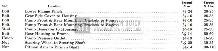
1959 Buick Power Steering Gear Tightening Specifications
1959 Buick Power Steering Gear Specifications
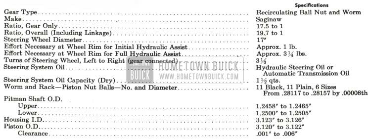
1959 Buick Power Steering Gear Specifications
1959 Buick Power Steering Pump Specifications
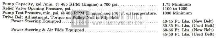
1959 Buick Power Steering Gear Pump Specifications
8-9 DESCRIPTION OF ROTARY VALVE 1959 BUICK POWER STEERING GEAR AND PUMP
The rotary valve 1959 Buick power steering system is standard equipment on the 4700 and 4800 Series and is offered as optional equipment on the 4400 and 4600 Series.
The 1958 power steering system was used on a few early 1959 Series 4400 cars. See the 1958 Buick Chassis Service Manual for information on servicing this system.
The rotary valve 1959 Buick power steering gear gives precise, positive steering with very little driver effort. Initial hydraulic assist is obtained with approximately .3 degrees of steering wheel rotation and one pound of effort at the steering wheel rim. Full hydraulic assist is obtained with approximately 4 degrees of wheel rotation and 31,4 pounds of effort at the wheel rim.
The hydraulic pump is used to supply oil under pressure to operate the steering gear. With the engine idling, oil flow is 1.75 GPM. The housing of the pump is enclosed in a reservoir which minimizes the possibilities of external leakage. A twist-off cap is used on the reservoir to simplify checking the oil level. See Figure 8-11.
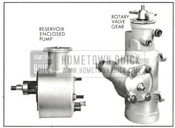
1959 Buick Rotary Valve Power Steering Gear and Pump
With the engine running, steering is entirely manual under conditions which require an effort of less than one pound at the steering wheel rim. When a greater effort is required, the power mechanism operates to assist in turning the front wheels. The effort then required at the steering wheel rim is limited to a maximum of approximately 3 1/4 pounds for normal steering and parking conditions.
When the engine is not running or if any part of the power mechanism is inoperative, the steering gear will operate manually giving the driver full control of the car.
The driver’s effort on the steering wheel is always proportioned to the force necessary to turn the front wheels. When the effort on the wheel drops to less than one pound, power assistance ceases. When the steering wheel is released to recover from a turn, the front wheels return to the straight-ahead position in the normal manner without assistance or interference from the power mechanism. Through this conventional steering action the driver always has the “feel” of steering.
1959 Buick Power Steering Gear Assembly
The 1959 Buick power steering gear assembly is the recirculating ball type, having a ratio of 17.5 to 1.
The upper end of the pitman shaft has a gear sector meshing with a rack-piston nut. The one piece rack-piston nut serves as a nut for the recirculating balls and as a power piston to which the oil under pressure is applied. The rack-piston nut has a Teflon piston ring located on its lower outside diameter which serves as a seal between the rack-piston nut and its cylinder gear housing. See Figure 8-12.
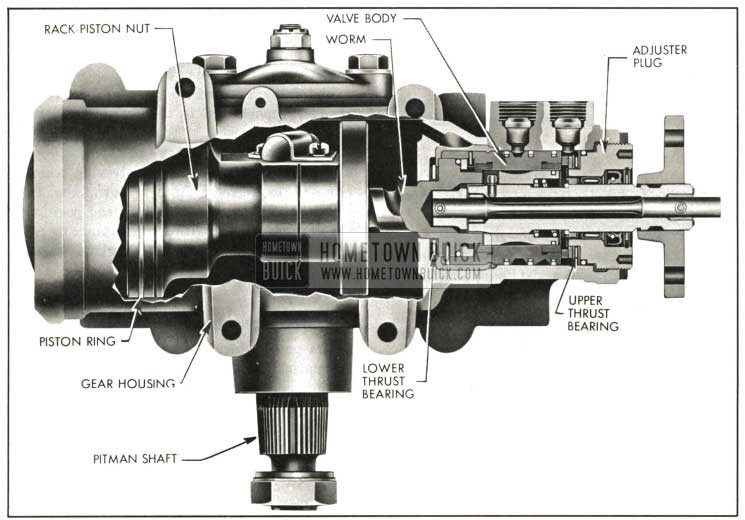
1959 Buick Power Steering Gear Assembly
A worm shaft turns in the rack-piston nut using the selectively fitted steel balls as a rolling thread. The ball groove is shallower in the center of the worm so that when the proper size balls are used, there is a slight worm to rack-piston nut preload in the straight-ahead position.
Worm shaft radial loads are transmitted to the gear housing through the rack-piston nut. Worm end thrust is caused by the tendency of the worm to thread itself into or out of the rack-piston nut as the steering wheel is turned right or left. This end thrust is absorbed entirely by the upper and lower thrust bearings. The upper thrust bearing is located between the valve body and adjuster plug and the lower thrust bearing is located between the housing and upper end of worm.
The upper steering shaft is a separate shaft supported in the steering column jacket. Its upper end is supported by a ball bearing and its lower end by an adapter and ball bearing assembly.
The steering shaft is connected to the 1959 Buick power steering gear through a flexible coupling. This flexible coupling helps absorb minor shocks and vibrations, dampens out hydraulic noises and gear rattle and also allows slight variations in alignment between the gear assembly and the steering column jacket assembly.
The 1959 Buick power steering gear identification number is stamped on approximately the center of the gear housing side cover. The first 3 digits show the day of the year (1 through 365) the gear was tested. The last digit shows the year (8 for 1958, etc.).
1959 Buick Rotary Valve Assembly
The 1959 Buick rotary valve assembly controls the flow of oil from the pump to the proper side of the rack-piston nut when power assistance is required and cuts off this flow when power assistance is not required.
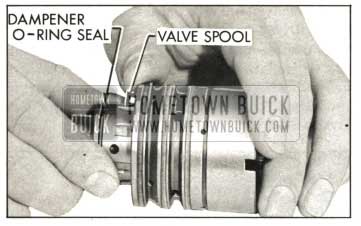
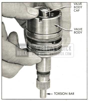
The 1959 Buick rotary valve assembly is located in the upper section of the gear housing and consists of a stub shaft, a torsion bar, a valve body, a valve spool and a valve body cap. See Figure 8-13.
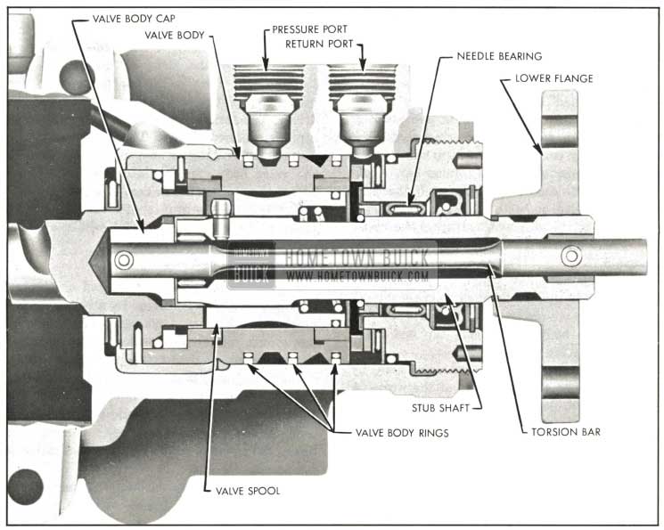
1959 Buick Rotary Valve Assembly
The stub shaft is attached to the upper steering shaft through the flange assembly. The lower flange is splined to the stub shaft and is retained by a pinch bolt. The torsion bar is located in the center of the stub shaft. The valve spool is an open center valve and is positioned on the lower end of the stub shaft. The valve body encloses the valve spool. The valve body cap is located at the lower end of the valve body.
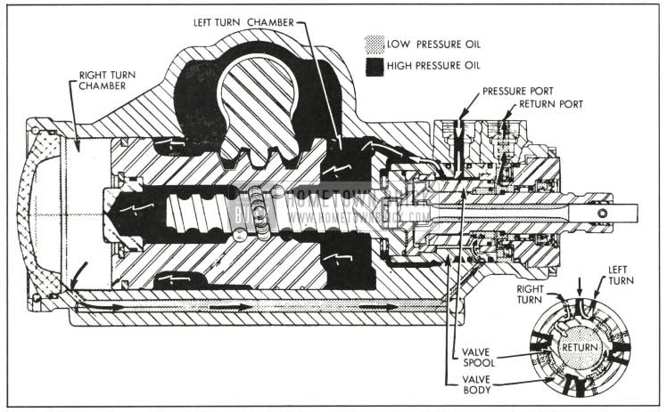
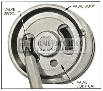
The valve body has two large oil grooves around its outside diameter. Each groove has four holes drilled into the inside diameter of the valve body. The lower groove is lined up with the pressure port in the gear housing. The upper groove is lined up with a drilled passage in the housing which directs oil to the right turn chamber in the housing, located at the lower end of the rack-piston nut. Three valve body Teflon rings provide leak proof seals for the oil grooves on the valve body. The inside diameter of the valve body has eight slots machined in it, four are connected to the pressure groove by the four drilled holes. See Figure 8-14.
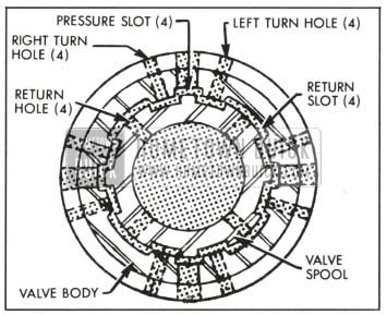
1959 Buick Upper End View of Valve Body and Valve Spool
The other four slots, which are wider, are connected to the return port in the housing through the valve spool. Near the center of the valve body are four other drilled holes which are used to direct oil to a passage in the housing that opens to the left turn chamber. This chamber is located at the upper end of the rack-piston nut.
The valve spool which fits inside the valve body may have an outside diameter as low as only .0004 in. smaller than the inside diameter of the valve body. This close fit allows very little, if any, oil flow between the two surfaces. The valve spool has four holes drilled near the upper end of it which are in line with the four return slots in the valve body. These holes allow oil to flow from the return slots in the valve body to the center of the spool and on to the return port in the housing. The outside diameter of the spool has eight slots machined on it, four are for opening the right turn holes in the valve body to the pressure slots or to the return slots in the valve body. The other four slots on the spool serve the same function for the left turn holes in the valve body.
Basically the 1959 Buick rotary valve assembly is divided into two separate assemblies which are fastened together by the torsion bar. To completely understand how the rotary valve functions, it must be known what parts are firmly attached together. Starting with the stub shaft which is fastened to the steering wheel through the upper steering shaft, the first assembly consists of the stub shaft, valve spool and upper end of the torsion bar. A pin on the outside diameter of the stub shaft retains the valve spool to it and a pin at the upper end of the stub shaft attaches the upper end of the torsion bar and shaft together. See Figure 8-15.
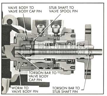
1959 Buick Attaching Pins for Valve Parts
The other assembly which is connected to the wheels of the car through linkage, pitman shaft and rack-piston nut, consists of the worm, valve body, valve body cap and lower end of the torsion bar.
The worm is attached to the valve body by a pin located at the upper end of the worm. A pin on the inside diameter of the valve body fastens the valve body cap to the valve body. To complete this assembly, a pin attaches the valve body cap to the lower end of the torsion bar.
When there is resistance to turning between the roadbed and the wheels of the car, the parts attached to the worm will also resist turning. Thus, when the steering wheel is turned by the driver, the torsion bar will deflect and allow the stub shaft and valve spool to rotate with the steering wheel. When this occurs, the relationship between the valve spool and valve body is changed and oil flow is directed by the slots on the valve spool through the holes in the valve body to the proper side of the rack-piston nut to assist the driver. The torsion bar deflection is limited to a predetermined amount. The upper end of the worm has two tangs which fit through slots in the valve body cap and into two slots in the end of the stub shaft. In case of a power mechanism failure, the stub shaft will contact the tangs of the worm and steering will be manual.
1959 Buick Oil Pump and Hoses
The oil pump, which is mounted on the engine in position to be driven by a belt from the crankshaft balancer, converts some engine power into oil pressure which is used against the rack-piston nut to rotate the pitman shaft.
Only one pump is used for all 1959 Buick power steering equipped cars. When a car is equipped with air ride, the oil pump and air ride compressor are both driven by the same belt; therefore, a heavy duty belt is used and the belt tension is increased.
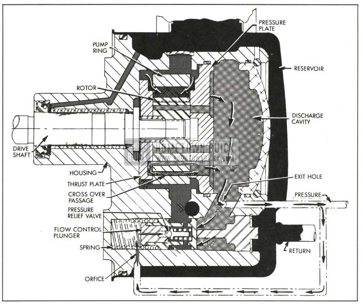
The 1959 Buick pump reservoir encloses the pump housing and provides a reserve supply of oil to assure complete filling of the hydraulic system. See Figure 8-16. The reservoir cap is vented which permits escape of any air that may be introduced into the system during assembly of the various units and maintains atmospheric pressure in the reservoir.
1959 Buick Oil Pump Assembly
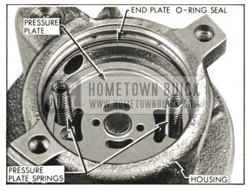
The 1959 Buick pump housing encloses the rotor assembly and the flow control plunger and spring. The rotor assembly consists of a drive shaft, a thrust plate, a rotor with ten vanes, a pump ring and a pressure plate. Inside the flow control plunger is a pressure relief valve.
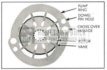
The rotor is loosely splined to the end of the drive shaft, is located adjacent to the face of the thrust plate and is enclosed by the pump ring. See Figure 8-17.
1959 Buick Pump Ring and Rotor
The rotor has a pressed-in sleeve which fits through the thrust plate and keeps the rotor in alignment. The rotor contains ten vanes which slide radially outward to contact the hardened and ground inside cam surface of the ring. As the shaft and rotor rotate, centrifugal force and fluid pressure against the inner ends cause the vanes to follow the cam contour of the ring. The cam surface is so shaped that two opposite pumping chambers are formed which cause a complete pumping cycle to occur every 180 degrees of rotation of the rotor. The pump ring has two crossover passages drilled in it which transfer oil from the thrust plate into a discharge cavity located at the rear of the pressure plate. In each pumping chamber, the increasing pockets formed between rotor, vanes and ring pick up oil from two openings, one between the pressure plate and ring and the other between the thrust plate and ring. See Figure 8-8. The oil is then propelled by the decreasing pockets in each pumping chamber into the discharge cavity through an opening in the pressure plate and an opening in the thrust plate which is connected to the crossover passage in the ring. The oil flows from the discharge cavity into a passage which is open to the rear of the flow control plunger and to a restricted exit hole in the housing. A certain quantity of oil flows through the exit hole and on to the steering gear rotary valve assembly. The exit hole also is connected to another passage in the housing (shown out of location at bottom of Figure 8-16) which directs oil through an orifice and into the spring chamber of the flow control plunger. Pressure in the discharge cavity is always greater than the pressure of the oil that has passed through the restricted exit hole.
The flow control plunger regulates the opening of a by-pass passage through which oil may be returned back to the suction and reservoir section of the pump. The oil under pressure flowing through the by-pass at high velocity causes an increase in pressure in the suction section of the pump.
When the pump is running without demand for steering pressure, pressure in the discharge cavity is great enough to push the flow control plunger open against a spring load of approximately ten pounds. The pressure in the spring chamber tends to close the plunger but, since pressure in the discharge cavity is always greater than in the spring chamber, the plunger is not closed. The movement of the plunger is controlled by the spring tension and the difference in pressure on the front and rear side of the plunger.
When power steering is demanded and the steering gear rotary valve restricts free circulation of oil as described later (Par. 8-10), the pump pressure builds up rapidly. When pump output pressure reaches a predetermined maximum, the increased pressure in the spring chamber forces the pressure relief valve open and oil escapes from the spring chamber into the by-pass passage. As oil pressure is relieved in the spring chamber, the high pressure in the pump discharge cavity overcomes the reduced pressure in the spring chamber plus the spring load to completely open the flow control plunger. Oil is then pumped into the by-pass passage until the line pressure opposing the pump drops below the relief valve setting permitting this valve to close. The flow plunger then resumes normal operation.
The flow control plunger starts to open at 300-400 RPM of pump and is functioning when the pump is running 465 RPM ( 400 RPM of engine). The minimum flow a new pump must produce is 1.75 gal. per minute at 465 pump RPM against a pressure of 700 psi. The flow plunger permits a maximum flow of 2.3 gal. per minute at 1500 RPM against a pressure of 50 psi. The pressure relief valve is set for 1100 to 1200 psi.
The 1959 Buick power steering pump identification number is stamped on the lower front surface of the housing. The first 3 digits show the day of the year (1 through 365) the pump was tested. Next is a letter for manufacturer identification (S for Saginaw). The last digit shows the year (8 for 1958, etc.).
A pressure hose connects the exit hole in the pump housing to the rotary valve in the steering gear housing and a return hose connects the rotary valve to the pump reservoir.
8-10 OPERATION OF ROTARY VALVE 1959 BUICK POWER STEERING GEAR
Neutral or Straight-Ahead
1959 Buick Oil Flow in Neutral or Straight-Ahead Position
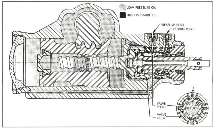
Figure 8-18 shows the rotary valve in the neutral or straight-ahead position. Oil flows from the pump into the pressure port of the gear, through the open center valve spool and back to the pump reservoir through the return port. The slots on the valve spool are so positioned in the valve body that the oil entering through the pressure port is directed to the return slots in the valve body, then through the center of the spool which is open to the return port. There is no flow to either side of the rack-piston nut, but each side is full of oil at all times. In the straight-ahead position the pressure on both sides is equal. The oil acts as a cushion that absorbs road shocks so they are not transferred to the steering wheel, thus giving safer and more effortless driving. In addition, this oil lubricates all the internal components of the gear.
All passages in the gear are open in the straight-ahead position and the valve remains in this position at all times except when effort applied to the steering wheel is more than one pound. The rotary valve’s open center position design reduces pump losses to a minimum by allowing a minimum of restriction to oil flow in the straight-ahead position.
Right Turn
1959 Buick Oil Flow In Right Turn Position
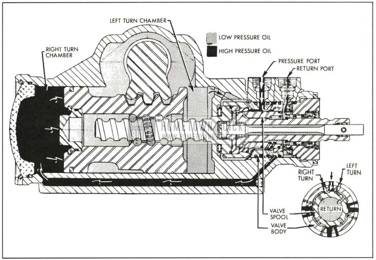
Figure 8-19 illustrates the operation of the gear when the steering wheel is turned to the right. Due to the resistance to turning between the front wheels and the roadbed, the torsion bar is deflected, changing the relationship between the slots in the valve spool and the slots in the valve body. The right turn slots on the valve spool are closed off from the return slots in the valve body and are opened more to the pressure slots. The left turn slots of the spool are closed off from the pressure slots and opened more to the return slots. This causes oil to flow into the right turn chamber of the housing and force the rack-piston nut upward. As the rack-piston nut moves upward, it applies turning effort to the 1959 Buick Pitman shaft.
The oil in the left turn chamber in the housing is simultaneously forced out through the valve and back to the pump reservoir. The higher the resistance to turning between the roadbed and the car wheels, the more the position of the valve spool is changed in relationship to the valve body and the higher the oil pressure on the lower end of the rack-piston nut. Since the amount of hydraulic pressure directed to the right turn chamber is dependent upon the resistance to turning, the driver is assured of the proper amount of smooth hydraulic assistance at all times.
The instant the driver stops applying steering effort to the steering wheel, the valve spool is moved back into its straight-ahead position in the valve body by the torsion bar. When this happens, the oil pressure is again equal on both sides of the rack-piston nut and the steering geometry of the car causes the wheels to return to the straight-ahead position.
Left Turn
1959 Buick Oil Flow Left Tum Position
Figure 8-20 illustrates the operation of the gear when the steering wheel is turned to the left. The resistance to turning of the front wheels causes the torsion bar to deflect, changing the relationship between the valve spool slots and the valve body slots. The slots are reversed from the right turn position and change the flow of oil into the left turn chamber in the housing, moving the rack-piston nut downward. Thus, turning effort is applied to the pitman shaft. The oil in the right turn chamber is forced through the valve back to the reservoir. When the driver stops applying steering effort, the valve spool returns to its straight-ahead position.
Steering Effort
During normal driving, the steering wheel effort will range from 1 to 2 1/4, pounds. The parking effort ranges from 2 to 3 1/4 pounds, depending upon the road conditions. Full hydraulic assist is obtain a with approximately 3 1/4 pounds of effort at steering wheel rim. The more the turning resistance, the greater the pressure in the right or left turn chamber and the more effort the driver must apply to the steering wheel to turn the car. This proportional effort gives the driver the “feel of the road” at all times.
During normal driving conditions, the hydraulic oil pressure in the turn chambers should not exceed 125 psi. Pressure for cornering should not exceed 400 psi and parking pressure may range up to 1100-1200 psi depending upon the road surface.
8-11 TROUBLE DIAGNOSIS – 1959 BUICK POWER STEERING GEAR AND PUMP
This paragraph covers only those causes of trouble which may be due to the hydraulic power mechanism. Causes which are due to the steering linkage and front suspension are the same as described for standard steering gear in Paragraph 8-3.
Hard Steering While Driving
- Lower coupling flange rubbing against adjuster plug. Loosen pinch bolt and assemble properly.
- Steering adjustment tight. Check adjustment by dropping pitman arm from gear or disconnecting linkage from pitman arm ball.
- Insufficient pressure build-up in power cylinder due to leak or faulty valve. Replace defective parts.
Poor Return of Steering Gear to Center
- Lower coupling flange rubbing against adjuster plug. Loosen pinch bolt and assemble properly.
- Steering gear misalignment. Re-shim at frame.
- Tight pitman sector to rack-piston nut adjustment. Adjust in car to specification.
- Rack-piston nut to worm preload too tight. Remove gear and replace balls as required.
- Thrust bearing adjustment incorrect. Remove gear and adjust to specification.
- Sticky valve spool. Remove and clean valve. Replace rotary valve assembly if necessary.
Pump Inoperative, or Poor or No Assist
NOTE: Refer to subpar. k, step 4 to deter- mine if pump is at fault.
- Loose drive belt. Tighten belt.
- Low oil level. Fill reservoir.
- Air in the oil. Locate source of air leak and correct.
- Defective hoses. Correct by either repairing or replacing hoses.
- Flow control valve stuck open. Remove burrs or dirt.
- Loose screw in end of flow control valve. Tighten.
- Pressure plate not flat against ring. Properly seat pressure plate against ring.
- Extreme wear of pump ring. Replace part.
- Scored pressure plate, thrust plate and /or rotor. Lap away light scoring. Replace heavily scored parts.
- Vanes not installed properly. Install properly.
- Vanes sticking in rotor slots. Free up by removing burrs or dirt.
- Faulty flow control valve assembly. Replace assembly.
Car Leads to One Side or the Other
Badly worn valve. Replace valve assembly.
Momentary Increase in Effort When Turning Wheel Fast to the Right
- Air in system. Bleed gear.
- Low oil level in pump. Check oil level in pump reservoir.
- High internal leakage. Replace rack-piston ring, rack-piston nut end plug seal, and /or replace valve.
Momentary Increase in Effort When Turning Wheel Fast to the Left
- Air in system. Bleed gear.
- Low oil level in pump. Check oil level in pump reservoir.
- High internal leakage. Replace rack-piston ring, rack-piston nut end plug seal, and /or replace valve.
External Oil Leaks
Wipe gear and pump thoroughly and make sure source of leakage is determined.
- Gear leaks.
- Loose hose connections. Tighten.
- Damaged hose. Replace.
- Side cover O-ring seal. Replace seal. (d) Pitman shaft seal. Replace seals.
- Housing end plug O-ring seal. Replace seal.
- Adjuster plug O-ring seal. Replace seal.
- Torsion bar O-ring seal. Replace valve.
- Pitman shaft lash adjuster nut. Replace nut.
- Stub shaft seal. Replace seal.
- Pump leaks.
- Oil leaking at top of reservoir as it is too full. Remove oil to proper level.
- Oil leaking at top of reservoir caused by air bubbles in oil. Locate course of air leak and correct.
- Reservoir O-ring seal damaged. Replace O-ring.
- Reservoir O-ring seal improperly installed. Install properly.
- Pressure union or studs not tightened sufficiently. Torque union to 20 foot pounds and studs to 30 foot pounds.
- Pressure union or studs cross threaded or damaged at seat. Replace damaged parts.
- Defective pressure fitting seat on hose end. Replace hose.
- Damaged pressure union O-ring seals. Replace seals.
- Defective shaft seal. Replace seal.
- Damaged shaft at seal area. Replace shaft.
- Leaks in metal parts. Replace defective part. (Example: Drawing crack in reservoir.)
Noise
- Gear noise (rattle or chuckle).
- Loose over-center adjustment. Adjust to specification.
NOTE: A slight rattle may occur on turns because of the increased lash off the “high point.” This is normal and the lash must not be reduced below the specified limits to eliminate this slight rattle. - Gear loose on frame. Check gear-to frame mounting bolts. Tighten bolts to 60 foot pounds.
- Loose over-center adjustment. Adjust to specification.
- Gear noise (“hissing” sound).
- A hissing noise is natural when steering wheel is at end of travel or when slowly turning at stand-still. Do not replace valve unless “hiss” is extremely objectionable. Investigate clearance around safety drive riveted pins. Be sure there is no metal-to-metal contact around flexible coupling as this will transmit valve hiss to car.
- Pump noise.
- Loose belt. Tighten belt.
- Hoses touching other parts of car. Adjust hose positions.
- Low oil level. Fill reservoir.
- Air in the oil. Locate source of air leak and correct.
- Excessive back pressure caused by hoses or steering gear. Locate restriction and correct. With pressure gauge installed in pressure hose between pump and gear and engine running at 1500 RPM and without turning the steering wheel, pressure should not exceed 125 psi.
- Scored pressure plate. Lap away light scoring. Replace heavily scored part.
- Vanes not installed properly. Install properly.
- Vanes sticking in rotor slots. Free up by removing burrs or dirt.
- Extreme wear of pump ring. Replace part.
- Face of thrust plate scored. Lap away light scoring. Replace heavily scored part.
- Scored rotor. Lap away light scoring. Replace heavily scored part.
- Defective flow control plunger. Replace.
- Valve noise (squawk when turning or when recovering from a turn).
- Cut or worn dampener O-ring on valve spool. Replace dampener O-ring.
- Loose or worn valve. Replace rotary valve assembly.
Excessive Wheel Kickback or Loose Steering
- Air in system. Add oil to pump reservoir and bleed.
- Excessive lash between pitman shaft sector and rack-piston. Adjust to specification.
- Loose thrust bearing adjustment. Remove gear and adjust to specification.
- Rack-piston nut to worm preload too low. Remove rack-piston nut and worm, and change balls to obtain specified preload.
1959 Buick Steering Wheel Surges or Jerks When Turning With Engine Running
Loose pump belt. Adjust to specification.
Hard Steering When Parking
- Loose pump belt. Adjust to specification.
- Low oil level in reservoir. Fill to proper level. If excessively low, check all lines and joints for evidence of external leakage.
- Steering gear adjustments tight. Adjust to specification.
- Insufficient oil pressure. If all the above checks do not reveal the cause of hard steering make the following tests of oil pressure:
- Disconnect the pressure line at oil pump. Attach pressure gauge to pump. Connect the hose to end of gauge where the valve is located.
- With engine at warm idle and gauge valve open, note the oil pressure on the gauge while turning steering wheel from one extreme position to the other. Especially note the maximum pressure which can be built up with the wheel held in either right or left extreme position.
CAUTION: Do not hold wheel in extreme position for an extended period of time because it will drastically increase the oil temperature and will cause undue wear on the oil pump. - With oil temperature between 150°F and 170°F, as measured with a thermometer in the reservoir, the maximum oil pressure should not be less than 1000 psi for satisfactory power steering operation.
- If the maximum oil pressure is less than 1000 psi, it indicates trouble in the pump, oil hoses, steering gear, or a combination of these parts. To eliminate the hoses and gear, close the gauge valve and quickly test pressure of the pump only with the engine at warm idle, then open the valve to avoid increasing oil temperature. A minimum pressure of 1000 psi should be present with valve closed.
- Comparing the maximum pressures obtained in these two tests will indicate source of trouble as follows: Step (b) pressure low, and Step (d) pressure normal-indicates faulty external oil lines or steering gear. Step (b) and Step (d) pressures equally low-indicates faulty oil pump.
- Low oil pressure in gear caused by restriction in hoses.
- Check for kinks in hoses. Remove kink.
- Foreign object stuck in hose. Remove hoses and remove restricting object or replace hose.
- Low oil pressure due to steering gear.
- Leakage at side cover O-ring, housing end plug O-ring, pitman shaft seals. Replace defective seals.
- Pressure loss in cylinder due to worn piston ring or scored housing bore. Remove gear from car for disassembly and inspection of ring and housing bore.
- Leakage at valve rings, valve body to worm seal, rack-piston end plug seal. Remove gear from car for disassembly and replace seals.
- Loose fit of spool in valve body or leaky valve body. Replace rotary valve assembly.
No effort required to turn
Broken torsion bar. Replace valve.
8-12 REMOVAL AND INSTALLATION OF 1959 BUICK PITMAN SHAFT SEALS, STEERING GEAR AND OIL PUMP
Removal and Installation of 1959 Buick Pitman Shaft Seals with Steering Gear in Car
If, upon inspection of the gear, it is found that oil leakage exists at the 1959 Buick pitman shaft seals, the seals may often be replaced without removing gear assembly from car as follows:
- Disconnect pitman arm from pitman shaft.
- Thoroughly clean end of pitman shaft and gear housing, then tape splines on end of pitman shaft to insure that seals will not be cut by splines during disassembly and assembly.
NOTE: Only one layer of tape should be used; an excessive amount of tape will not allow the seals to pass over it, due to the close tolerance between the seals and the pitman shaft.
- Remove pitman shaft seal retaining ring with No. 3 Truarc pliers J-4245.
- Start engine and turn steering wheel fully to the left so that oil pressure in the housing can force out pitman shaft seals. Turn off engine.
NOTE: Use suitable container to catch oil forced out of gear. This method of removing the pitman shaft seals is recommended, as it eliminates the possibility o f scoring the housing while attempting to pry seals out.
- Inspect seals for damage to rubber covering on OD. If OD appears scored, inspect housing for burrs and remove before attempting new seal installation.
- Clean the end of housing thoroughly so that dirt will not enter housing with the installation of the new seals.
- Lubricate the seals thoroughly with petroleum jelly and install seals with Installer J-6219. Install the inner single lip seal first, then a back-up was}J.er. See Figure 8-45. Drive seal in far enough to provide clearance for the other seal, back-up washer and retaining ring. Make sure that the inner seal does not bottom on the counter bore. Install the outer double lip seal and the second back-up washer in only far enough to provide clearance for the retaining ring. Install retaining ring.
- Fill pump reservoir to proper level, start engine and turn wheel to left and check for leaks.
- Remove tape and reinstall Pitman arm.
Removal of 1959 Buick Power Steering Gear
- Place fender cover over left front fender.
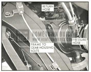
- Disconnect the pressure and return line hoses at the steering gear and elevate ends of hoses higher than pump to prevent oil from draining out of pump.
- Disconnect the two upper-to-lower flange bolts. See Figure 8-21.
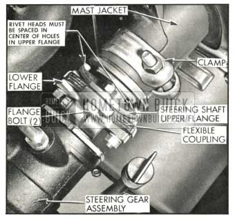
1959 Buick Power Steering Gear Coupling
1959 Buick Power Steering Gear Attaching Bolts
Installation of 1959 Buick Power Steering Gear Assembly
- Install the 1959 Buick gear assembly by reversing the procedure for removal. See Paragraph 8-8 (a) for tightening specifications.
IMPORTANT: When installing gear assembly in car, the riveted pins on the lower flange and flexible coupling must be installed in the center of their correct slots in the upper flange (small pin in small slot and large pin in large slot). See Figure 8-21. The clip on the loose end of the horn ground wire must be installed on flange bolt between flexible coupling and upper flange.
- Fill the pump reservoir with automatic transmission oil (engine stopped).
- NOTE: Make sure that all hose connections are tight.
- Start engine to run pump. Maintain proper oil level in the reservoir by adding oil as required.
- When oil level remains constant, rotate the steering wheel through its entire range slowly a few times with engine running.
- Recheck oil level, then replace reservoir cap.
NOTE: If air becomes trapped in the oil, the oil pump may be noisy until all air is out of oil. This may take some time since air trapped in oil does not bleed out rapidly.
Removal of 1959 Buick Oil Pump
- Disconnect belt from pump pulley and remove pulley nut. Remove pump pulley using a suitable three-jaw puller.
- Disconnect return and pressure hoses from pump. See Figure 8-23. Use shipping plugs and caps to cover the hose connector and union on pump and open ends of the hoses to avoid entrance of dirt.
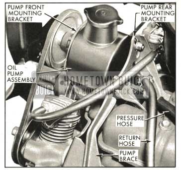
1959 Buick Oil Pump to Engine Mounting
Installation and Bleeding of Oil Pump
- Install the oil pump by reversing the procedure for removal. See Paragraph 8-8 (a) for tightening specifications.
- When pump is reinstalled on engine, adjust drive belt tension by using torque wrench applied to the pulley nut. With a new belt the tension should be set so the pulley will slip in belt when 1,0-1.5 ft. lbs. torque is applied to pulley nut. With a used belt the torque should be 30-35 ft. lbs. If equipped with air ride the belt tension should be: New belt 50-55 ft. lbs.; Used belt 1,.5-50 ft. lbs.
- Fill the reservoir to proper level with specified automatic transmission oil. Start engine to run pump. Maintain oil level in reservoir by adding oil if necessary.
- When oil level remains constant, rotate the steering wheel through its entire range slowly a few times with engine running, then check oil level and correct if necessary. Replace reservoir cap.
8-13 ADJUSTMENT OF 1959 BUICK POWER STEERING GEAR AND LINKAGE
Adjustment of 1959 Buick Power Steering Gear in Car
- Disconnect 1959 Buick pitman arm from intermediate tie rod and check tightness of Pitman arm nut with an 18″ wrench.
NOTE : Never attempt to adjust steering gear with pitman arm connected to intermediate rod.
- Turn 1959 Buick steering wheel slowly through its full travel to check for binding; tight spots or uneven action.
- Turn steering wheel to extreme right or left position. Apply Scale J-544-A to a spoke at rim of wheel and, while pulling scale at 90 degrees to spoke, check the pull required to turn the wheel steadily in the range where lash normally exists between rack-piston nut and pitman shaft sector. The lash range exists for one eighth turn of steering wheel from either extreme position.
- The reading on the scale should be between 1/2 and 1 1/4, pounds, which would indicate normal pre-load at the thrust bearing and drag at the valve assembly.
NOTE :The scale reading should be close to the minimum specification on a gear that has been in use for a short period of time. On a new gear the reading will be greater because of the higher valve drag. This drag drops off rapidly when gear is operated.
- Loosen pitman lash adjuster lock nut and turn lash adjuster counterclockwise a few turns.
- Check the pull required to turn the wheel through the “high-point” or no lash range. The reading should be 1/8 to 5/8 pound higher than previous reading, which would indicate normal ball preload between worm and rack-piston nut.
- If readings are not within specifications, remove 1959 Buick power steering gear and recheck adjustment on bench as outlined in sub. paragraph b.
- If readings are within specifications turn pitman shaft lash adjuster clockwise as required to obtain a scale reading 1/2 to 1 pound higher than was obtained in step 6. This reading is taken when pulling wheel through “high-point” with lock nut tight. Total reading should be between 1 1/8 to 2 1/2 pounds.
IMPORTANT: Total reading should be kept to a minimum. The only case when reading would be near maximum is on a new gear (see note in Step 1).
Adjustment of 1959 Buick Power Steering Gear Out of Car
- This adjustment is made when the gear is completely assembled. Assemble 1959 Buick power steering gear assembly to Fixture J-6448. See Figure 8-24.
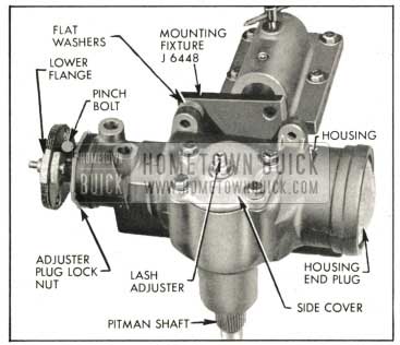
1959 Buick Steering Gear Assembled to Mounting Fixture
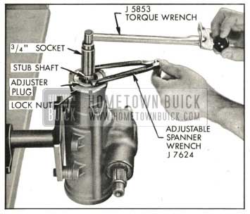
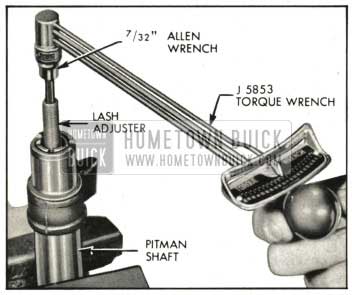
1959 Buick Adjusting Thrust Bearing Preload
Then tighten adjuster plug until thrust bearing preload is 3 to 4 inch pounds in excess of drag measured with adjuster plug backed out. Total of thrust bearing preload and valve drag should not exceed 8 inch pounds.
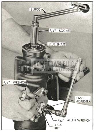
1959 Buick Adjusting Pitman Shaft Lash Adjuster
This reading is taken when rotating stub shaft through “high-point” range with lash adjuster nut tight. Hold lash adjuster from rotating with Allen wrench and tighten lash adjuster nut securely. Total “high-point” pull should not exceed 16 inch pounds.
Adjustment of 1959 Buick Power Steering Linkage
Refer to Figure 8-5 for the correct adjustment of both manual and power steering linkage.
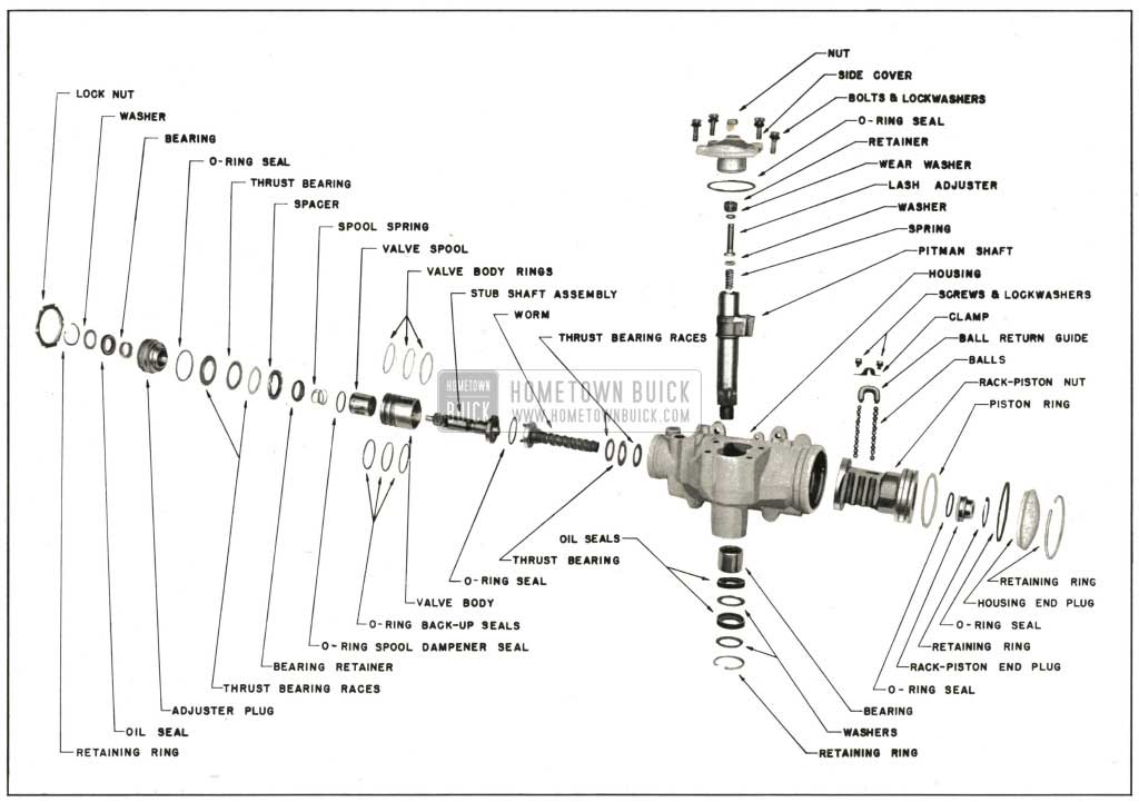
1959 Buick Exploded View of Rotary Valve Power Steering Gear
8-14 DISASSEMBLY, INSPECTION AND ASSEMBLY OF 1959 BUICK ADJUSTER PLUG ASSEMBLY AND ROTARY VALVE ASSEMBLY
Removal of 1959 Buick Adjuster Plug Assembly and Rotary Valve Assembly
- Thoroughly clean exterior of gear assembly with a suitable solvent. Drain the unit by placing the valve ports down and turning the worm through its entire range two or three times.
- Assemble gear housing to fixture, J-6448. See Figure 8-24.
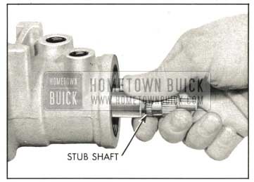
- Mark the stub shaft and lower flange for correct assembly. Remove lower flange pinch bolt (7/16″, 12 point socket) and remove flange from stub shaft.
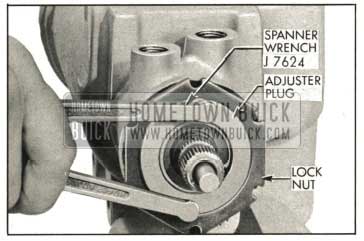
- Loosen adjuster plug lock nut and remove adjuster plug using adjustable spanner wrench, J-7624. See Figure 8-28.
1959 Buick Removing Adjuster Plug Assembly
1959 Buick Removing Rotary Valve Assembly
NOTE: If it is only necessary to service the rotary valve assembly, proceed with sub paragraph e. below.
Disassembly of 1959 Buick Adjuster Plug Assembly
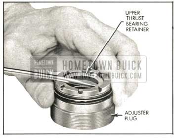
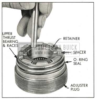
- Remove the upper thrust bearing retainer with a screw driver, being careful not to damage the needle bearing bore. See Figure 8-30. Discard retainer. Remove thrust bearing spacer, upper thrust bearing and thrust bearing races.
1959 Buick Removing Upper Thrust Bearing Retainer
1959 Buick Removing Stub Shaft Seal Retaining Ring
1959 Buick Removing Needle Bearing
Inspection of 1959 Buick Adjuster Plug Assembly
- Inspect thrust bearing spacer for cracks.
- Inspect thrust bearing rollers and thrust bearing races for wear, pitting, scoring, cracking or brinelling. Replace any damaged parts.
Reassembly of 1959 Buick Adjuster Plug Assembly
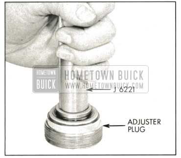
- If needle bearing was removed because of damage, install new needle bearing from thrust bearing end of adjuster plug, by pressing against identification end of bearing using Tool J-6221. End of bearing must be flush with bottom surface of stub shaft seal bore.
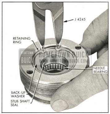
- Lubricate new stub shaft seal with automatic transmission oil and install seal and back-up washer with spring in seal toward plug using Tool J-5188. Install seal only far enough in adjuster plug to provide clearance for retaining ring. See Figure 8-33. Install retaining ring with No. 3 Truarc Pliers, J-4245, making certain ring is properly seated.
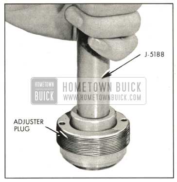
1959 Buick Installing Stub Shaft Seal
1959 Buick Installing Upper Shaft Thrust Bearing Retainer
Disassembly of 1959 Buick Rotary Valve Assembly
NOTE: It is very uncommon to have to make any service repairs to the valve assembly with the possible exception of the valve spool dampener O-ring seal. DO NOT disassemble the valve unless absolutely necessary since this may result in damaging the assembly. If the valve spool dampener O-ring seal requires replacement, remove the valve spool only, replace the O-ring and reinstall the spool immediately. DO NOT disassemble further.
CAUTION: Cleanliness of parts, tools and work area is of the utmost importance during servicing of the valve assembly.
- Remove cap to worm O-ring seal and discard.
- Remove valve spool spring by prying on small coil with a small screw driver to work spring onto bearing surface of stub shaft. Slide spring off shaft. Be very careful not to damage stub shaft surface.
- Remove the valve spool by holding the valve assembly in one hand with the stub shaft pointing downward. Insert the end of a . pencil of wood rod through the opening in the valve body cap and lightly push on the valve spool until it is far enough out of the valve body to be withdrawn. See Figure 8-35.
1959 Buick Separating Valve Spool From Valve Body
Withdraw the spool with a steady rotating pull to prevent jamming. See Figure 8-36.
1959 Buick Withdrawing Valve Spool From Valve Body
If slight sticking occurs, make a gentle attempt to reverse the withdrawal procedure. If this does not free spool, it has become cocked in the valve body bore. Do not attempt to force the spool in or out if it becomes cocked, but continue with the following step.
CAUTION: The valve spool must be removed with extreme care. The clearance between the valve body and the spool may be as low as .0004 inch. The slightest cocking of the spool may jam it in the valve body.
- Remove the stub shaft, torsion bar and cap assembly by holding the valve assembly with stub shaft downward as shown and rapping torsion bar lightly against work-bench to dislodge the cap from valve body to cap pin. See Figure 8-37. Complete the removal of the stub shaft torsion bar and cap assembly.
1959 Buick Removing Stub Shaft, Torsion Bar and Cap Assembly From Valve Body
Inspection of 1959 Buick Rotary Valve Assembly
NOTE: The 1959 Buick rotary valve assembly is a precision unit with selectively fitted parts and is hydraulically balanced when assembled at the factory. Only those parts which are listed in parts book are replaceable and interchangeable. No other valve parts are individually interchangeable. If replacement of any non-serviceable valve part is necessary, the rotary valve assembly should be replaced.
- If the valve assembly leaks externally between the torsion bar and stub shaft, the valve assembly should be replaced. The torsion bar O-ring seal in the stub shaft is not serviced.
- Inspect the pin in the valve body that engages the valve cap for being badly worn, cracked, or broken. If the pin is damaged the valve assembly should be replaced.
- Inspect the smaller of the two grooves in the valve body. If it is worn badly the valve assembly should be replaced.
- Inspect the valve spool drive pin in the stub shaft. If it is worn badly, cracked or broken the valve assembly should be replaced.
- Examine the valve spool O.D. and the valve body I.D. for nicks, burrs or bad wear spots. If any are found, the valve assembly should be replaced. A slight polishing is normal on the valving surfaces.
- Check the fit of the spool in the valve body. Lubricate the spool with automatic transmission oil and install it in the valve body without the dampener O-ring seal on it. The spool should rotate smoothly without binding or catching. If spool does not rotate smoothly, the valve assembly should be replaced.
- Measure the length of the valve spool spring. The free length should be approximately 3/4 to 7/8 inch. If it measures 11/16 inch or less, the spring should be r laced because this indicates that the spring has taken a set.
- Examine the needle bearing surface on the , stub shaft for being badly worn, brinelled or scored. If damaged, the valve assembly should be replaced.
Reassembly of 1959 Buick Rotary Valve Assembly
CAUTION: All parts must be free and clear of dirt, chips, etc., before assembly and must be protected after assembly.
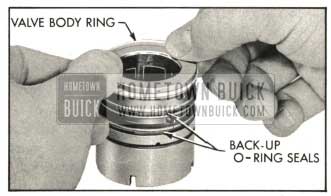
- If removed from valve body, lubricate three new ring back-up O-ring seals in automatic transmission oil and assemble in the three ring grooves on the valve body. Do not allow the seals to become twisted. Assemble three new valve body rings in the ring grooves over the O-ring seals by carefully slipping over the valve body. See Figure 8-38.
1959 Buick Installing Valve Body Rings
NOTE : The valve body rings may appear loose or twisted in the grooves, but the heat of the oil during operation after assembly will cause them to straighten.
- Lubricate a new valve dampener O-ring seal in automatic transmission oil and install in valve spool groove. Do not allow seal to twist in grooves.
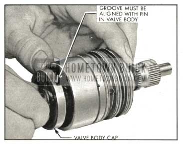
- Assemble the stub shaft torsion bar and cap assembly in the valve body, aligning the groove in the valve cap with the pin in the valve body. See Figure 8-39.
1959 Buick Assembling Stub Shaft, Torsion Bar and Cap Assembly In Valve Body
Tap lightly on the cap with a soft mallet until cap is against the shoulder in the valve body. Valve body pin must be in the cap groove. Hold these parts together during the rest of valve assembly.
CAUTION: Because the clearance between the spool and valve body is very small, extreme care must be taken when assembling these parts.
- Place seal protector J-6222 over stub shaft and slide valve spool spring over stub shaft with smaller diameter coil going over end of shaft last. See Figure 8-40. Work spring on shaft with a small screw driver until small coil of spring is seated in the stub shaft groove. Be careful not to damage surface of shaft.
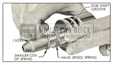
1959 Buick Installing Valve Spool Spring
NOTE : Spring must be seated properly in groove in stub shaft.
- Lubricate a new cap to worm O-ring seal in automatic transmission oil and install in valve body.
NOTE: If during the assembly of the valve, the stub shaft and valve cap were allowed to slip out of engagement with the valve body pin, the spool will be permitted to enter the valve body too far. The spool dampener O-ring seal will expand into the valve body oil slots and will prevent withdrawal of the spool. If this has occurred, attempt to withdraw spool with a slight pull and much rotary motion. If this does not free the spool make sure spool is free to rotate and place valve body on a flat surface with notched end up. Tap spool with wooden or plastic rod until O-ring seal is cut and spool can be removed. Install new dampener O-ring seal and proceed with assembly as before starting with step 2 above.
Installation of 1959 Buick Rotary Valve Assembly and Adjuster Plug Assembly
- Align the narrow pin slot on the valve body with the valve body drive pin on the worm. Insert the valve assembly into the gear housing by pressing against the valve body with the finger tips. Do not press on stub shaft or torsion bar. See Figure 8-41.
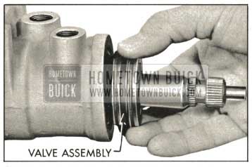
1959 Buick Inserting Valve Assembly In Housing
The return hole in the gear housing should be fully visible when valve is assembled properly. See Figure 8-42.
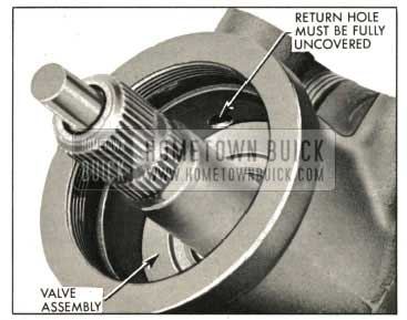
1959 Buick Valve Assembly Properly Installed In Housing
CAUTION: Do not push against the stub shaft during assembly as this may cause the stub shaft and cap to pull out of the valve body, allowing the spool dampener O-ring seal to slip into valve body oil grooves. Be sure valve is properly seated before installing adjuster plug assembly.
- Place seal protector J-6222 over end of stub shaft. Install adjuster plug assembly in gear housing snugly with adjustable spanner wrench J-7624 then back plug off approximately 1/8 turn. Install adjuster plug lock nut if removed, but do not tighten.
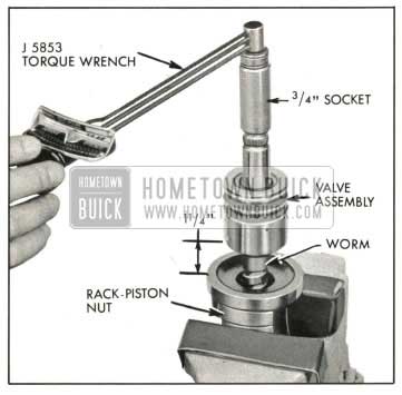
- Adjust the thrust bearing preload. Attach torque wrench J-5853 with a 3/4 inch, 12 point deep socket to the stub shaft. Turn stub shaft to approximately 1/2 turn from either extreme if rack-piston nut has not been removed from housing. Slowly rotate wrench in an arc approximately 60° (1/6 turn) in both directions several times to measure valve drag and record reading. See Figure 8-25. Then tighten adjuster plug until thrust bearing preload is 3 to 4 inch pounds in excess of valve drag measured with adjuster plug backed-out. Total of thrust bearing preload and drag should not exceed 8 inch pounds.
IMPORTANT NOTE: When rack-piston nut and pitman shaft have not been removed from gear housing, total “high-point” pull (approximately 2 1/4 turns from extreme right turn position) should be a minimum of 5 inch pounds higher than thrust bearing preload and drag. Total “high-point” pull should not exceed 16 inch pounds. If reading over “high-point” is not within limits it will be necessary to check the rack-piston nut ball preload and pitman shaft adjustment as instructed in Paragraph 8-13 (b).
- Tighten adjuster plug lock nut with adjustable spanner wrench J-7624. Recheck thrust bearing preload to be sure that tightening lock nut did not change adjustment.
- Install lower flange on stub shaft, lining up marks on the shaft and flange. Center bolt hole with groove on stub shaft.
- Install lower flange pinch bolt (7/16″ socket) and tighten to 20 ft.lbs.
8-15 DISASSEMBLY, INSPECTION AND ASSEMBLY OF 1959 BUICK PITMAN SHAFT ASSEMBLY
Removal of 1959 Buick Pitman Shaft Assembly
- Thoroughly clean exterior of gear assembly with a suitable solvent. Drain the unit by placing the valve ports down and turning the worm through its entire range two or three times.
- Assemble gear housing to fixture J-6448. See Figure 8-24.
- Rotate the stub shaft until pitman shaft gear is in center position (approximately 21,4 turns from extreme right position). Remove the housing side cover retaining bolts.
- Tap the end of the 1959 Buick pitman shaft with a soft mallet and slide shaft out of housing.
- Remove the side cover O-ring seal and discard.
Disassembly of 1959 Buick Pitman Shaft Assembly
- Remove the 1959 Buick pitman shaft seal retaining ring from end of housing using No. 3 Truarc Pliers J-4245 and remove outer seal back-up washer. Tap a screw driver between the outer seal and the inner back-up washer and pry out seal. Tap the screw driver between the inner seal and the shoulder in the gear housing and pry out inner seal. Be careful not to damage the seal bore in housing. Discard seals.
- Check the 1959 Buick pitman shaft needle bearing for being worn, pitted or scored. If damaged, remove needle bearing from gear housing bore by driving from the seal bore side of housing using Tool J-6657. See Figure 8-43. Discard bearing.
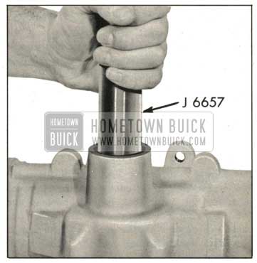
1959 Buick Removing Pitman Shaft Needle Bearing
lnspection of 1959 Buick Pitman Shaft Assembly
- Inspect 1959 Buick pitman shaft bearing surface in side cover for excessive wear or scoring. If worn or scored, replace side cover.
- Check the pitman shaft sector teeth and the bearing and seal surfaces. If worn, pitted or scored replace pitman shaft.
- Check the torque on the lash adjuster. See Figure 8-44. Torque should between 1and 8 inch pounds.
1959 Buick Checking Torque on Lash Adjuster
Reassembly of1959 Buick Pitman Shaft Assembly
- If 1959 Buick pitman shaft needle bearing was removed because of damage, install new needle bearing into gear housing bore from seal bore end, pressing against stamped identification on bearing with Tool J-6657. Press in until bearing clears shoulder in gear housing, .030″ maximum. Rollers in bearing must be free to rotate.
- Lubricate new pitman shaft seals in automatic transmission oil. Install the inner, single lip seal in bore first, then a back-up washer. See Figure 8-45.
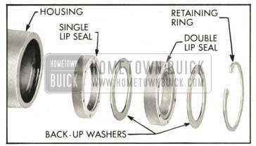
1959 Buick Pitman Shaft Seals
Using Tool J-6219, drive the seal and washer in far enough to provide clearance for the outer seal, back-up washer and retaining ring. See Figure 8-46.
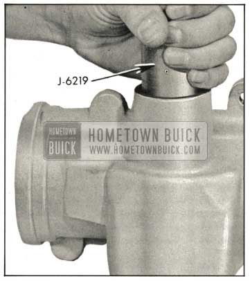
1959 Buick Installing Pitman Shaft Seals
The inner seal must not bottom on the counter bore. Install the outer double lip seal and the second backup washer in bore only far enough to provide clearance for the retaining ring with Tool J-6219. Install retaining ring with No.3 Truarc Pliers Tool J-4245, making certain that ring is seated properly.
Installation of 1959 Buick Pitman Shaft Assembly
- Lubricate a new side cover O-ring seal in automatic transmission oil and install in groove in the face of side cover.
- Turn the stub shaft until the center groove of the rack-piston is aligned with the center of the pitman shaft hole.
- Wrap masking tape over the end of 1959 Buick pitman shaft. Install the pitman shaft so that the center tooth in the sector meshes with the center groove of the rack-piston nut. Make sure the side cover O-ring seal is in place before pushing the side cover down on gear housing. Remove masking tape from end of shaft.
- Install the four side cover bolts with lock washers and tighten to 30 ft.lbs.
- Install new lash adjuster nut on lash adjuster, but do not tighten. Adjust pitman shaft as outlined in Paragraph 8-13 (b).
8-16 DISASSEMBLY, INSPECTION AND ASSEMBLY OF 1959 BUICK RACK PISTON NUT AND WORM ASSEMBLY
Removal of 1959 Buick Rack-Piston Nut and Worm Assembly
- Thoroughly clean exterior of gear assembly with a suitable solvent. Drain the unit by placing the valve ports down and turning the worm through its entire range two or three times.
- Assemble gear housing to Fixture J-6448. See Figure 8-24.
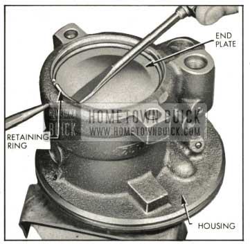
- Rotate housing end plug retainer ring so that one end of ring is over hole in gear housing. Spring one end of ring with punch to allow screw driver to be inserted to lift ring out. See Figure 8-47.
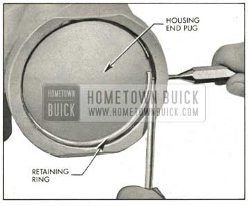
1959 Buick Removing Housing End Plug Retaining Ring
CAUTION: Do not rotate farther than necessary or the balls from the rack-piston and worm assembly will fall out.
- Remove and discard housing end plug O-ring seal.
- Remove rack-piston nut end plug retaining ring using No. 3 Truarc Pliers J-4245. Pull out rack-piston end plug with water pump pliers. See Figure 8-48.
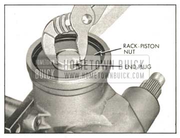
1959 Buick Removing Rack-Piston Nut End Plug
1959 Buick Removing Rack-Piston Nut From Housing
Turn stub shaft so that rack-piston nut will go onto the tool and remove rack-piston nut from gear housing. Keep ball retaining tool completely through rack piston nut to prevent balls from falling out.
Disassembly of 1959 Buick Rack-Piston Nut and Worm Assembly
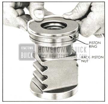
- Cut and remove piston ring on rack-piston nut and discard ring.
- Remove ball return guide clamp to rack piston nut screws and lockwashers and remove clamp.
- Place the 1959 Buick rack-piston nut on a clean cloth and remove ball return guide and ball retaining tool. Make sure all 22 balls are caught on the cloth.
Inspection of 1959 Buick Rack-Piston Nut and Worm Assembly
- Inspect gear housing bore. If badly scored or worn, replace housing.
- Inspect the worm and rack-piston nut grooves and all the balls for excessive wear or scoring. Inspect rack-piston nut teeth for pitting, wear or scoring. Inspect O.D. of rack-piston nut for wear, scoring or burrs. If either the worm or rack-piston nut need replacing, both must be replaced as a matched assembly.
- Inspect ball return guides, making sure that the ends where the balls enter and leave the guides are not damaged. Replace if necessary.
- Inspect lower thrust bearing and races for wear, pitting, scoring or cracking. Replace any damaged parts.
- Inspect the hose connectors on gear housing. If badly brinelled or scored, replacement will be necessary. To remove the connectors, tap threads using 5/16-18 tap. Thread a bolt with a nut and flat washer into the tapped hole. Pull the connector by holding the bolt and turning the nut off the bolt. Wash and blow the housing out thoroughly to remove any tapping chips. To install new connector, use Replacer J-6217 to drive connector in place.
- Inspect the ball plug in gear housing. If it is leaking or raised above the housing surface, it may be driven in flush to %6 inch below surface. The ball can be tightened by staking the housing. If the leakage cannot be stopped, the housing should be replaced.
Reassembly of 1959 Buick Rack-Piston Nut and Worm Assembly
- Thoroughly clean and lubricate the internal parts with automatic transmission oil.
- Install new piston ring on rack-piston nut by inserting ring in groove as shown and carefully working it around rack-piston nut. See Figure 8-50.
1959 Buick Installing Piston Ring on Rack-Piston Nut
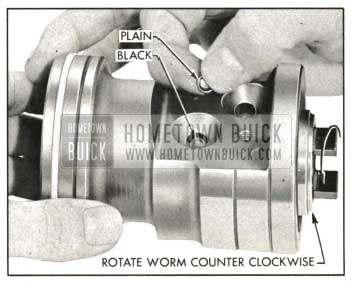
1959 Buick Loading Balls In Rack-Piston Nut
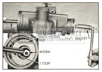
Attach torque wrench J-5853 with 3/4 inch, 12 point deep socket to the stud shaft. See Figure 8-52.
1959 Buick Checking Rack-Piston Nut Ball Preload
Rotate the wrench through a total arc of approximately 60 degrees (1/6 turn) in both directions several times and take a reading. The highest reading obtained with the worm rotating should be from 1 to 5 inch pounds. If the reading is too high, disassemble and reassemble, using the next size smaller plain balls and recheck. (A rack-piston nut with a ball size of 7 does not have a number stamped on the flat surface. For ball sizes other than 7, the ball size is stamped on the flat surface of the rack-piston nut.) If the reading is too small, use the next size larger plain balls and recheck. Remove valve assembly from worm.
- Turn the 1959 Buick rack-piston nut and worm assembly to a horizontal position in the vise and insert ball retaining tool J-7539 in end of worm and turn worm out of the rack-piston nut. Do not allow the tool to separate from the worm until worm is fully removed from rack-piston nut.
Installation of 1959 Buick Rack-Piston Nut and Worm Assembly
- Assemble lower thrust bearing (1″ I.D. x 1 5/8″ O.D.) and races on worm. Install new cap to worm O-ring seal. Assemble rotary valve assembly to worm by aligning narrow pin slot in valve body with pin on worm.
- Insert the valve assembly and worm in gear housing as an integral unit. See Figure 8-42. Continue installation of rotary valve assembly and adjuster plug assembly as outlined in Paragraph 8-14 (h). Do not install lower flange on stub shaft.
NOTE : The thrust bearing preload should be adjusted to read between 3 and 4 inch pounds in excess of valve assembly drag. Total reading .including valve assembly drag not to exceed 8 inch pounds.
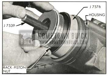
- Install ring compressor sleeve tool J-7576 in gear housing and hold it tightly against shoulder in the housing. See Figure 8-53.
1959 Buick Installing Rack-Piston Nut in Housing
Insert the rack-piston nut into the housing until the ball retaining tool J-7539 engages the worm. Turn the stub shaft, drawing the rack piston nut into the housing. When the piston ring is into the housing bore, the ball retaining tool and the ring compressor may be removed.
8-17 DISASSEMBLY, INSPECTION AND ASSEMBLY OF 1959 BUICK SAGINAW OIL PUMP
Disassembly of 1959 Buick Saginaw Oil Pump
- Use shipping caps to cover the hose union and pipe on pump and thoroughly clean exterior of pump.
- Remove reservoir cap and drain out oil in pump reservoir.
- Install pump in a soft jaw vise with pump shaft pointing down. Do not clamp pump too tightly in vise as this may distort bushing.
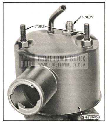
- Remove two reservoir to pump housing studs and special sealing flat washers. See Figure 8-54.
1959 Buick Oil Pump Reservoir
1959 Buick Removing End Plate Retaining Ring
1959 Buick Pump Housing With End Plate Removed
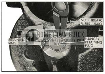
1959 Buick Removing Plunger Plug Retaining Ring
CAUTION: The plunger retaining plug is spring loaded and may pop out of housing.
- 13. Remove flow control plunger and spring from housing.
NOTE : Do not disassemble flow control plunger as this is a factory assembled unit.
- 14. Remove shaft seal, if defective, with Remover J-5822 installed on a suitable slide hammer. See Figure 8-58. Be careful not to expand remover on surface of housing bushing.
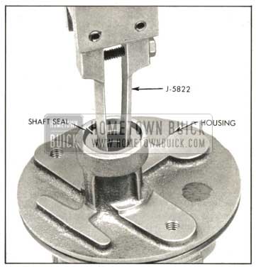
1959 Buick Removing Shaft Seal
Inspection of 1959 Buick Saginaw Oil Pump Parts
- Clean shaft with solvent. Wipe dry with clean, lint-free cloth and inspect shaft for wear. Clean all parts thoroughly with solvent before inspecting.
- Check fit of the ten vanes in slots of rotor; vanes must slide freely but fit snugly in slots. Tightness may be removed by thorough cleaning or removal of irregularities using a hard Arkansas stone. Replace rotor if excessive looseness exists between rotor and vanes, and replace vanes if they are irregularly worn or scored. Light scoring on the rotor can be repaired by carefully lapping surface of rotor.
- Inspect all ground surfaces of the rotor ring for roughness or irregular wear. Slight irregularities may be removed with a hard Arkansas stone. Replace ring if inside cam surface is scored or worn and inspect outside radius of vanes very closely for damage.
- Inspect the surfaces of the pressure plate and thrust plate for wear or scoring. Light scoring can be repaired by carefully lapping until surface is smooth and flat, after which all lapping compound must be thoroughly washed away.
- Inspect the control plunger bore in the housing for scoring, burrs or other damage. Hair line scratches are normal. Inspect bushing in housing, if worn or scored replace housing.
- Inspect the surfaces of the flow control plunger for scores and burrs. Hair line scratches are normal. Replace plunger if badly scored or if it is the cause of low pump pressure. Check the small screw in the end of the plunger, if loose, tighten being careful not to damage machined surfaces.
- Inspect the stud sealing flat washers. If seal in washer is damaged, replace washer.
Assembly of 1959 Buick Oil Pump
NOTE: Use Figure 8-59, Exploded View of Oil Pump as a guide during assembly.
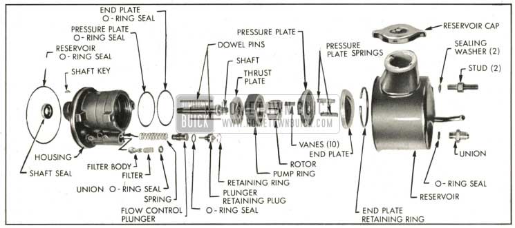
1959 Buick Exploded View of Oil Pump
- Make sure all parts are absolutely clean. Lubricate seals and moving parts with automatic transmission oil during assembly.
- If shaft seal was removed, use Installer J-7017 to drive new seal into housing with spring side of seal toward housing. See Figure 8-60. Seal must be firmly seated in housing.
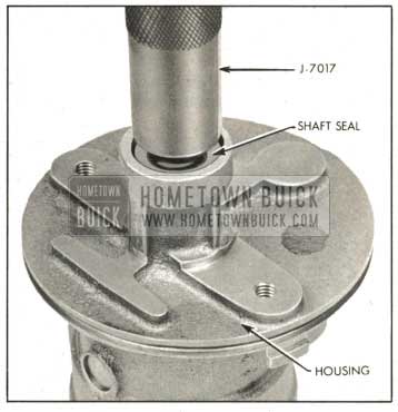
1959 Buick Installing Shaft Seal
NOTE: Arrow on outer edge of pump ring points in direction of pump rotation.
- Install rotor on pump shaft with alignment sleeve toward front of housing. Rotor must be free on shaft splines.
- Install ten vanes in rotor slots with radius edge toward outside and flat edge toward center of rotor.
- Lubricate the outside diameter and chamber of pressure plate with petroleum jelly and install on dowel pins with ported face toward pump ring. Dowel pins fit into slots in plate that are nearest outside diameter of plate. Use a soft plastic or wood rod and lightly tap around outside diameter of pressure plate to seat it. See Figure 8-61.
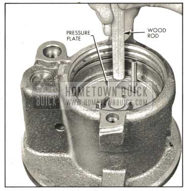
1959 Buick Seating Pressure Plate In Housing
Pressure plate will travel about 1/16″ to seat. Never press or hammer on the center of pressure plate as this will cause permanent distortion and result in pump failure.
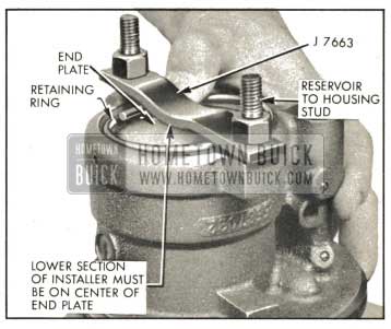
1959 Buick Installing Housing End Plate and Retaining Ring
Attach installer to housing using the reservoir to housing studs with long end of studs threaded in housing. Press end plate down by tightening studs until ring groove in housing is evenly exposed. Install retaining ring. Be sure ring is completely seated in housing groove and end plate is aligned properly. Remove studs.
CAUTION: Press end plate into housing only far enough to install retaining ring in groove.
- Install new reservoir O-ring seal on housing. Place filter assembly in outlet hole. Place new union O-ring seal in counter bore in housing.
- Install reservoir on housing and line up holes for studs and union. Tap reservoir with a soft mallet to seat it on housing. Install reservoir to housing studs with sealing flat washers. Tighten studs to 30 ft. lbs. Be sure that reservoir O-ring was not unseated or damaged during reservoir to housing assembly.
- Assemble new O-ring seal on union. Install union on pump and tighten to 20 ft. lbs.
- Remove pump from vise and install shaft key on shaft. Support shaft on the opposite side while installing key.
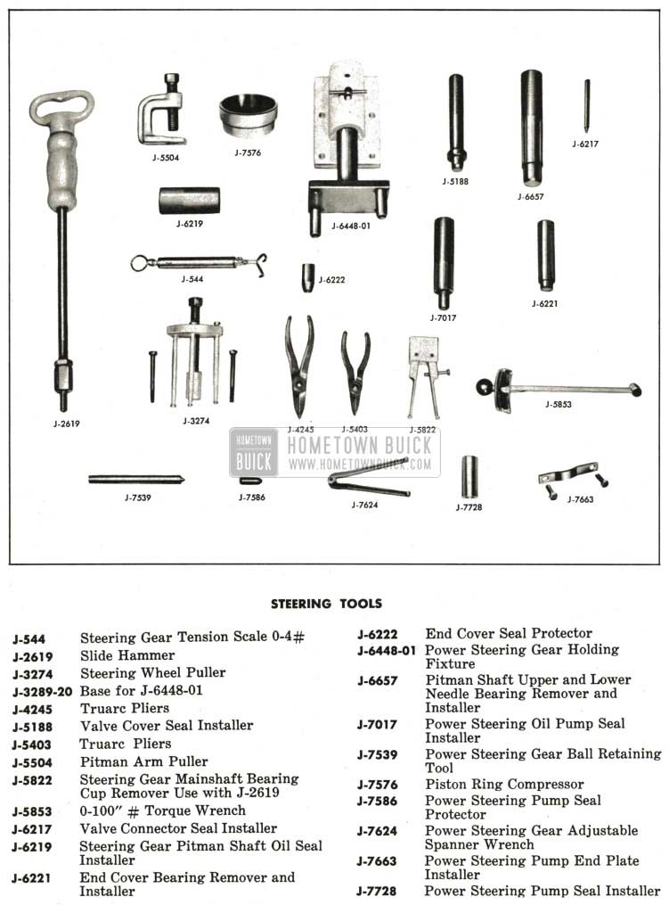
1959 Buick Steering Gear and Linkage Special Tools
Leave A Comment
You must be logged in to post a comment.