SECTION 2-B 1959 BUICK ENGINE DESCRIPTION
2-4 1959 BUICK ENGINES AND MOUNTINGS
1959 Buick Engines in Each Series
The 1959 Buick V-8 engines used in all series are of the same basic design, differing in displacement, compression ratio, power, carburetor equipment and manifolding.
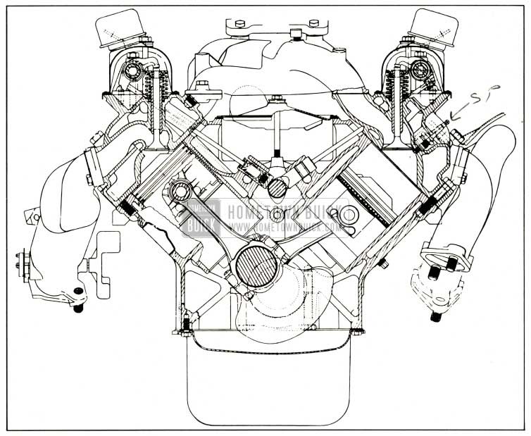
1959 Buick Engine End Sectional View
The 1959 Buick Series 4400 Synchromesh engine is equipped with a cast iron flywheel for clutch application, while the engines used with automatic transmissions are equipped with a triangular steel flywheel for torque converter application.
- Series 4400 engines. These engines have a bore of 4.125″ and a stroke of 3.4″ providing a displacement of 364 cubic inches. These engines are often referred to as “364” engines. Standard equipment on the 364 engines is 2 barrel carburetor and 2 port intake manifold. A factory installed optional power pack, available on automatic transmission jobs, includes a 4 port intake manifold and 4 barrel carburetor.
The Synchromesh engine has a compression ratio of 8.5 to 1 and the automatic transmission engine has a ratio of 10.5 to 1. The lower ratio of the synchromesh engine is accomplished by the use of pistons having a lower dome height than those used in the 10.5 to 1 ratio engine.
- Series 4600 , 4700, 4800 engines. These engines have a bore of 4.1875″ and a stroke of 3.640″ providing a displacement of 401 cubic inches. These engines are often referred to as “401” engines. All 401 engines are equipped with 10.5 to 1 compression ratio pistons, a 4 port manifold and 4 barrel carburetors and are coupled to either the twin turbine or triple turbine automatic transmission.
- Parts interchangeable between 364 and 401 engines.
Following is a list of major parts which are interchangeable between the two 1959 Buick engines. Other parts also are interchangeable but in every case the master parts list should be consulted before making replacements:
- Cylinder heads and bolts
- Inlet valves
- Exhaust valves
- Valve spring, inner and outer Valve spring cap and key Camshaft bearings
- Crankshaft bearing front, front intermediate and rear intermediate
- Connecting rod bearings
- Engine oil pan and gasket
- Oil pump and screen assembly
- Crankcase breather and air cleaner assembly
- Oil gauge rod
- Oil filter assembly and gasket
- Timing chain cover assembly and gasket
- Fan assembly
- Water pump cover assembly and gasket
- Left exhaust manifold on single (also on duals)
- Right exhaust manifold assembly Fuel pump, gasket, and eccentric Front engine mounts
- Timing chain and sprockets
- Hydraulic valve lifter
- Valve rocker arm
- Valve rocker arm shaft and bracket
- Valve rocker arm cover assembly and gasket
- Connecting rod bolt and nut
- Power pack air cleaner and silencer assembly
1959 Buick Engine and Transmission Mountings
The 1959 Buick engine and transmission assembly is supported in the frame on three synthetic rubber pads. One mounting pad is located on each side of the engine near the front end and approximately midway between top and bottom of the cylinder crankcase. The mounting pads are fastened between the crankcase and the cross member at front end of car frame. The front mountings are designed to support the weight of the 1959 Buick engine and control its torsional characteristics. See figure 2-2.
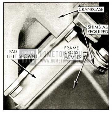
1959 Buick Front Engine Mounting
- Synchromesh and Twin Turbine Transmission mountings. The rear (transmission) mountings of synchromesh and Twin Turbine Transmission equipped cars are composed of two parts-a mounting pad to support part of the weight of the 1959 Buick engine and transmission assembly and a thrust pad to take the drive thrust from the rear wheels. The mounting pad is located between the transmission rear bearing retainer and the transmission support. The thrust pad is located between the rear edge of transmission support and a thrust plate extended downward from the rear bearing retainer. See figure 2-3.
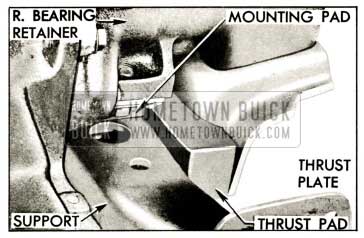
1959 Buick Synchromesh and Twin Turbine Mounting
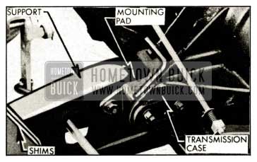
1959 Buick Triple Turbine Mounting
2-5 1959 BUICK ENGINE CONSTRUCTION
1959 Buick Cylinder Crankcase
The 1959 Buick cylinder crankcase has two banks of four cylinders each, which form a 90 degree angle. The crankcase section extends below the centerline of the crankshaft to form a continuous flat surface with the rear bearing cap and the 1959 Buick timing chain cover, permitting installation of the lower crankcase with a one-piece gasket. The upper portion of the flywheel housing is cast integral with the cylinder crankcase.
The right bank of cylinders (as viewed from rear) is set slightly forward of the left bank so that connecting rods of opposite pairs of cylinders can be connected to the same crankpin. Starting at front end, cylinders in the right bank are numbered 1-3-5-7 and cylinders in the left bank are numbered 2-4-6-8.
1959 Buick Crankshaft and Bearings
The 1959 Buick crankshaft is supported in the crankcase by five steel-backed full precision type bearings, all having the same nominal diameter.
All bearings are identical except those which take end thrust. The 364 engine crankshaft rear bearing is a thrust bearing as is the case with No. 3 bearing in the 401 engine. See figures 2-5 and 2-6.
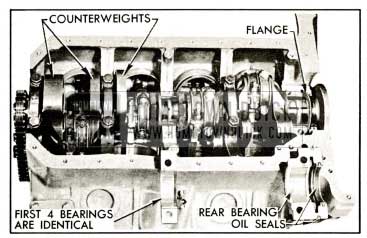
1959 Buick 364 Engine Crankshaft and Bearings
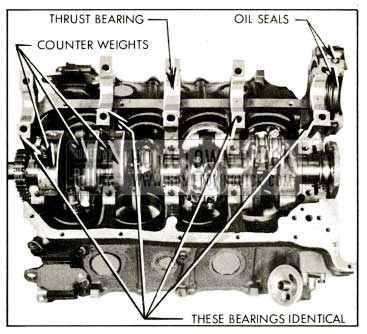
1959 Buick 401 Engine Crankshaft and Bearings
The 1959 Buick crankshaft is counterbalanced by weights forged integral with crank cheeks. Maximum counterweighing in the space available is obtained by machining the weights to a contour which allows a minimum uniform clearance with cylinder barrels and piston skirts. Additional counterbalancing is obtained by an offset flywheel flange.
All 1959 Buick engines are equipped with a harmonic balancer and fan pulley assembly.
1959 Buick Connecting Rods and Pistons
1959 Buick connecting rod s are steel drop forgings of 1-beam section, having bosses on each side so that metal can be removed as required to secure correct weight and balance during manufacture. The lower end of each rod is fitted with a steel backed full precision type bearing. The upper end of the 1959 Buick connecting rod has a hole into which the wrist pin is pressed. The outer ends of the pin float in the bosses in the piston.
The tin plated aluminum alloy pistons have full skirts and are cam ground. Two compression rings and one oil control ring are located above the piston pin. Two transverse slots in the oil ring groove extend through the piston wall and permit drain back of oil collected by the oil ring. Shallow depressions cast into the head provide clearance between the piston and valves in operation. See figure 2-7.
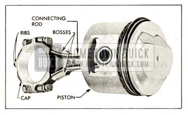
1959 Buick Connecting Rod and Piston Assembly
The cast iron compression rings in the two upper grooves of piston are distinguished by a small groove (a bevel on some rings) cut around the inner edge on one side. The rings are installed with identification mark up. See figure 2-36.
The oil ring in the lower groove consists of two thin steel rails separated by a spacer (fig. 2-36) and backed by an expander placed in the piston groove. The rails and spacer of a new ring are lightly held together with a cement which dissolves and releases the parts when oil is applied at start of operation.
1959 Buick Cylinder Heads
Both 1959 Buick cylinder heads are identical except for treatment of the water inlet ports which exist in both ends of each head. When a head is prepared for installation on one bank of cylinders, the water inlet port on the rear end is plugged and the front port is left open for connection to the water pump. This places the plugs in opposite ends of the right and left heads; therefore, the heads cannot be interchanged.
All valves are mounted vertically in the 1959 Buick cylinder head and in line from front to rear, so they operate at 45 degrees to the centerline of cylinders. The angle and location of the inlet valve and port causes the incoming fuel-air charge to sweep angularly downward to one side of the cylinder centerline, resulting in a whirling action which thoroughly mixes the charge and produces a beneficial turbulence during the compression stroke.
With the 1959 Buick spark plug located centrally in top of the combustion chamber the point gap is well exposed to the sweep of the incoming charge. This reduces the concentration of exhaust gases that may have remained in this area after exhaust of the previous charge. As noncombustible exhaust products are removed from the area around the spark plug the tendency toward misfiring at part throttle is reduced.
The central location of the spark plug causes burning of the fuel charge to proceed uniformly outward in all directions toward edges of the combustion space. The short flame travel speeds up the combustion process, causing the fuel mixture to burn in a shorter period of time than that at which detonation is likely to occur. High turbulence on the compression stroke and short flame travel following ignition permits the use of a high compression ratio with present day fuels.
1959 Buick Camshaft and Valve Mechanism
The 1959 Buick camshaft is located in the angle of the cylinder block above the crankshaft where it is supported in five steel-backed, babbitt-lined bearings. It is driven from the crankshaft by sprockets and a single outside guide type chain. See figure 2-8.
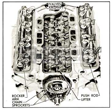
1959 Buick Engine Valve Mechanism
1959 Buick hydraulic valve lifters and solid one-piece steel push rods are used to operate the overhead rocker arms and valves of both banks of cylinders from the single camshaft. This system requires no lash adjustment at time of assembly or in service; therefore, no adjusting studs or screws are provided in the valve train. Construction and operation of the 1959 Buick hydraulic valve lifters are described in sub-paragraph f below.
The eight rocker arms for each bank of cylinders are mounted on a tubular steel shaft supported on the cylinder head by four die cast brackets. The 1959 Buick rocker arms are offset to accommodate the different planes of movement of the valves and the push rods which pass through the cylinder head to one side of the valves.
The valves operate vertically in guides pressed into the cylinder head and each valve has two concentric springs to insure positive seating throughout the operating speed range. Inlet valve heads are 1 7/8″ and exhaust valve heads are 1 7/2″ in diameter. Valves and rocker arms are protected by a cover which seats against a raised horizontal surface on each cylinder head, and a cork gasket insures against oil leaks.
1959 Buick Hydraulic Valve Lifters
In addition to its normal function of a cam follower, each hydraulic valve lifter also serves as an automatic adjuster which maintains zero lash in the valve operating linkage under all operating conditions. By eliminating all lash in the operating linkage and also providing a cushion of oil to absorb operating shocks, the 1959 Buick hydraulic valve lifter promotes quiet valve operation. It also eliminates the need for periodic valve adjustment to compensate for wear of parts.
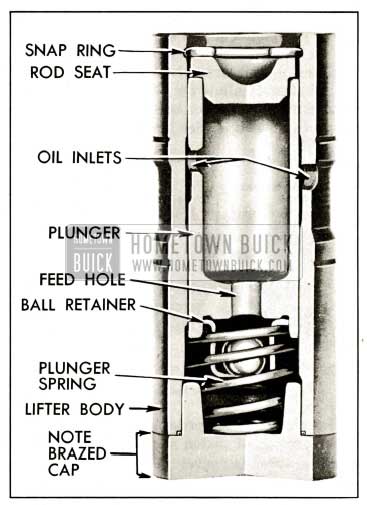
1959 Buick Hydraulic Valve Lifter, Sectional View
As shown in figure 2-9, all parts of a hydraulic lifter are housed in the body, which is the cam follower. The body and the plunger are ground to very close limits, then a plunger is selectively fitted to each body to assure free movement with very little clearance. The push rod seat is free to move with the plunger in the body and, as its name implies, it provides a spherical seat to support the lower end of the push rod.
The plunger and seat are pressed toward the upper end of the lifter body by a coil spring which also holds a check ball retainer against the lower end of the plunger; When lifter is out of 1959 Buick engine a spring wire retainer holds all parts in the body. The ball retainer holds a check ball in position over the lower end of a feed hole in the plunger and limits its travel to .004″-.008M. See figure 2-9.
When the valve lifter is installed in 1959 Buick engine the push rod holds the seat and plunger downward clear of the plunger retainer at all times. The plunger spring then presses the lifter body down against the camshaft and presses the plunger and seat up against the push rod with an eight pound load, which is enough to take up all lash clearances between parts in the valve linkage without affecting positive seating of the valve.
Oil is fed to all lifters through galleries in the crankcase, as described in paragraph 2-6. Oil enters each lifter through grooves and oil holes in the lifter body and plunger, and flows down into the chamber below the plunger through the feed hole in plunger. The first few cycles of operation after the 1959 Buick engine is started forces out all air and completely fills the plunger and lower chamber of each lifter with oil.
At the start of a cycle of valve operation the lifter body rests on the camshaft base circle, the plunger spring holds all lash clearances out of the valve linkage, and the check ball rests on its retainer so that the plunger feed hole is open to permit passage of oil between the plunger and lower chamber.
As the rotating camshaft starts raising the valve lifter body, oil in the lower chamber begins to flow through the open plunger feed hole but the flow immediately seats the check ball against the plunger to prevent appreciable loss of oil from the lower chamber. The lifting force against the body is then transmitted through the entrapped oil to the check ball and plunger so that the plunger and push rod seat move upward with the body to operate the linkage which opens the 1959 Buick engine valve.
As the camshaft rotates further to close the 1959 Buick engine valve the valve spring forces the linkage and lifter to follow the cam down. When the engine valve seats, the linkage parts and lifter plunger stop but the plunger spring forces the body to follow the cam downward .002″ to .003″ until it again rests on the camshaft base circle. Oil pressure against the check ball ceases when the plunger stops, the check ball drops down against its retainer, and the plunger feed hole is again opened to permit passage of oil between plunger and lower chamber.
During the valve opening and closing operation a very slight amount of oil escapes through the clearance between plunger and body and returns to the crankcase. This slight loss of oil (called “leakdown”) is beneficial in providing a gradual change of oil in the lifter, since fresh oil enters the lower chamber when the feed hole is opened at the end of each cycle of operation.
It should be noted that during each cycle of operation the vertical movement between the body and plunger is on4.y .002″ to .003″ but the check ball moves through its full travel of .004″ to .008″. Full opening of the plunger feed hole at the end of each cycle not only permits replacement of oil lost’ from the lower chamber, as previously described, but also permits control of the volume of oil in lower chamber to compensate for expansion and contraction of the valve linkage parts due to changes in 1959 Buick engine temperature.
When 1959 Buick engine temperature increases and the valve linkage parts expand, the plunger must move to a slightly lower position in the lifter body to assure full closing of the engine valve. When engine temperature decreases and the linkage parts contract, the plunger must move to a slightly higher position in body to prevent lash clearances in the valve linkage. In either case, the capacity of the lower chamber changes and the volume of oil present is automatically controlled by passage of oil through the open plunger feed hole.
2-6 1959 BUICK ENGINE LUBRICATION SYSTEM
The 1959 Buick engine lubrication system is of the force feed type in which oil is supplied under full pressure to crankshaft, connecting rods, and camshaft bearings, and is supplied under controlled volume to the valve lifters, rocker arm bearings, and push rods. All other moving parts are lubricated by gravity flow or splash.
Oil Supply. The supply of oil is carried in the lower crankcase (oil pan) which is filled through filler caps in the rocker arm covers. The filler openings are covered by combination filler and ventilating caps which contain filtering material to exclude dust. A removable oil gauge rod on right side of crankcase is provided for checking oil level.
Oil Pump. Oil is picked up and circulated by the spur-geared oil pump assembly which is mounted on the lower side of the cylinder crankcase at the rear end, where it extends down into the oil sump. The pump shaft is coupled to the ignition distributor shaft, which is driven from the camshaft through spiral gears. The pump inlet is equipped with a stationary screen of ample area. If the screen should become clogged for any reason, oil may be drawn into the pump over the top edge of the screen, which is held slightly clear of the screen housing by three embossments. The oil pump body contains a non-adjustable spring loaded pressure valve, which regulates the maximum oil pressure to 40 pounds.
Drilled passages in the oil pump body and cylinder crankcase conduct all oil from the pump to the oil filter.
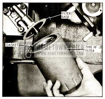
1959 Buick Engine Oil Filter Installation
Oil Filter. The AC full flow type oil filter is externally mounted on the right side of crankcase at the rear end. The filter permits rapid passage of oil with a minimum drop in pressure. Normally, ALL 1959 Buick engine oil passes through the filter element. If the element becomes restricted enough to produce 4 1/2 to 5 1/2 pounds difference in pressure between the inlet and outlet ports of the filter, a spring-loaded ball type valve in the filter base will open to by-pass the element and route oil directly into the main oil gallery.
Main Oil Gallery. The 1959 Buick main oil gallery runs full length of the crankcase in the angle below the camshaft. Through connecting passages drilled in the crankcase it distributes oil at full pressure to all crankshaft and camshaft bearings, from which oil is than distributed to all other working parts of the 1959 Buick engine. See figure 2-11.
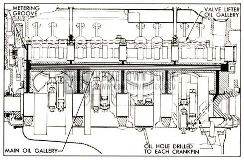
1959 Buick Oil Galleries-364 Engine Shown
1959 Buick Crankshaft , Rods, and Pistons. Holes drilled in the crankshaft carry oil from the crankshaft bearings to the connecting rod bearings. Pistons and cylinder walls are lubricated by oil forced through a small notch in the bearing parting surface on connecting rod, which registers with the hole in the crankpin once in every revolution. Piston pins are lubricated by splash.
Timing Chain and Sprockets. A small amount of oil which escapes from the 1959 Buick camshaft front bearing flows down the front face of the cylinder crankcase. A sheet metal trough mounted on the crankcase causes the oil to drop on the crankshaft sprocket, from which it is then transferred to the timing chain.
Valve Lifters and Oil Galleries. Oil holes in the crankcase and camshaft front bearing align with a groove in the 1959 Buick camshaft front bearing journal which meters the flow of oil from the main oil gallery to the valve lifter oil gallery in each bank of cylinders. The drilled oil gallery, running full length of each cylinder bank, cuts into the lower sides of all valve lifter guide holes to supply an adequate volume of low pressure oil to each hydraulic valve lifter. Oil enters each lifter through grooves and holes in the lifter body and the plunger. See figure 2-11 and 2-12.
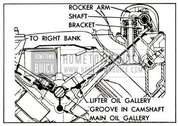
1959 Buick Oil Supply to Lifters, Rocker Arms and Valves
Rocker Arms, Valves, and Push Rods. The 1959 Buick rocker arms and valves on each cylinder head are supplied with low pressure oil from the valve lifter oil gallery through connecting passages drilled in the front end of cylinder block and head. See figure 2-12. The oil passage in cylinder head ends in a counter bored recess surrounding the bolt which attaches the rocker arm shaft front bracket. The oversize bolt hole through the bracket permits oil to flow up into the hollow rocker arm shaft, which is plugged at both ends.
Each rocker arm receives oil through a hole in the shaft, and parallel grooves in the rocker arm assure proper lubrication of the bearing surface. Oil is metered to the push rod ball seat and to the valve stem through holes drilled in the rocker arm. Excess oil drains off and returns to the oil pan through passages in cylinder head and cylinder block.
2-7 1959 BUICK ENGINE CRANKCASE VENTILATION
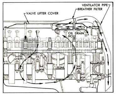
The 1959 Buick crankcase is ventilated by means of suction provided by a ventilator pipe which projects down under the car. Air passing the open end creates a suction when the car is moving forward. Air is drawn in through two ventilating type filter caps, located at the top center of each rocker arm cover. The air spreads out, ventilating the entire rocker arm area before being drawn down through the push rod holes in the heads. The air, well distributed by the push rod holes, enters the 1959 Buick crankcase and then flows to the rear and upward to enter the breather filter. The metal gauze filled breather filter is built into the rear end of the lifter cover to remove oil from the air stream before it leaves the crankcase. The air flow is reversed by baffles in the filter, thereby separating the oil which then drains back through a hole in the rear of the filter. After the oil is removed, the ventilating air is drawn down and out through the ventilator pipe.
1959 Buick Crankcase Ventilation
2-8 1858 BUICK ENGINE COOLING SYSTEM
The 1959 Buick engine cooling system is the pressure type, with thermostatic coolant temperature control and water pump circulation. A thermo gauge to indicate temperature of coolant is mounted on instrument panel. The gauge assembly includes a capillary tube with a bulb which attaches to the left cylinder head so as to extend into the water jacket.
A Harrison tube and center type of radiator core of brass and copper is used on all models. On automatic transmission equipped cars the lower radiator tank houses the transmission oil cooler.
All 1959 Buick engines are normally equipped with an 18 1/2″ unshrouded fan. Air conditioner equipped jobs have a 20″ shrouded fan driven by a torque sensitive clutch.
The 1959 Buick cooling system is sealed by a pressure type radiator filler cap which causes the system to operate at higher than atmospheric pressure. The higher pressure raises the boiling point of coolant and increases the cooling efficiency of the radiator. The fifteen pound pressure cap used on all series permits a possible increase of approximately 38° F. in boiling point of coolant.
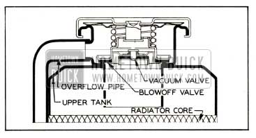
The pressure type radiator filler cap contains a blow off or pressure valve and a vacuum or atmospheric valve. See figure 2-14.
1959 Buick Pressure Type Radiator Cap Installation
The pressure valve is held against its seat by a spring of pre-determined strength which protects the 1959 Buick radiator by relieving the pressure if an extreme case of internal pressure should exceed that for which the cooling system is designed. The 1959 Buick vacuum valve is held against its seat by a light spring which permits opening of the valve to relieve vacuum created in the system when it cools off and which otherwise might cause the radiator to collapse.
The coolant is circulated by a centrifugal pump mounted on the timing chain cover which forms the outlet side of the pump. The fan and pulley(s) are bolted to the forward end of the pump shaft. In this manner both the fan and pump are belt driven by a crankshaft driven pulley mounted forward of the harmonic balancer.
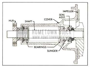
The pump shaft is supported on two single row ball bearings pressed on the shaft and shrunk fit in the aluminum water pump cover. The bearings are permanently lubricated during manufacture and sealed to prevent loss of lubricant and entry of dirt. The pump is sealed against coolant leakage by a packless non-adjustable seal assembly mounted in the pump cover in position to bear against the impeller hub. See figure 2-15.
1959 Buick Water Pump Cover Assembly
The inlet pipe cast on the pump cover feeds into the passage formed by the cover and the front face of the impeller, which is mounted on the bearing shaft with the vanes facing rearward. Coolant flows through the inlet passage to the low pressure area at the center, where it then flows rearward through three holes in the impeller. Vanes on the rotating impeller cause the coolant to flow radially outward into two discharge passages cast in the timing chain cover, and these passages deliver an equal quantity of coolant to each cylinder bank water jacket.
Cylinder water jackets extend down below the lower limit of piston ring travel and the coolant completely surrounds each cylinder barrel to provide uniform cooling. After flowing upward through connecting passages the coolant leaves the cylinder heads through a water manifold that provides a common connection between both heads and the radiator.
The 1959 Buick water manifold also houses the “pellet” type radiator thermostat and provides the bypass passage through which coolant returns to the water pump for recirculation whenever the thermostat valve closes to block circulation through the radiator. This thermostatically operated by-pass type of water temperature control permits the 1959 Buick engine to reach its normal operating temperature quickly. The thermostat valve opens at 167-172 degrees F.
Leave A Comment
You must be logged in to post a comment.