SECTION 5-C 1950 BUICK REAR AXLE REMOVAL AND DISASSEMBLY PROCEDURES
5-7 1950 BUICK REAR AXLE REMOVAL AND INSTALLATION
When to Remove Rear Axle Assembly
The 1950 Buick rear axle assembly should be removed from the car before overhaul if there is external indication of damage to rear axle or third member housings or strut rods, or if oil is leaking at torque ball or third member flanged joints. These conditions cannot be corrected with the rear axle assembly under the car.
On cars equipped with the 3.6 or 3.9 rear axle gear ratio it is necessary to remove the rear a le assembly whenever the propeller shaft must be removed because pinion pullers available for service will not fit over the pinions of these gear sets. Furthermore, on cars with Dynaflow Drive the propeller shaft spline oil seal (fig. 5-3) cannot be properly installed with third member housing connected to the torque ball.
On Series 40 cars equipped with Synchromesh transmissions and the 4.1 rear axle gear ratio, it is not necessary to remove the rear axle assembly in order to remove the propeller shaft since a puller is available for the pinion of this gear set.
1950 Buick Rear Axle Removal
- Place car stands solidly under frame so that rear end of car is high enough to permit working underneath.
- Disconnect parking brake cable at rear brake cable sheave and at bracket on front end of torque tube. Disconnect brake hose from pipe at frame X member and remove retainer. Plug hose and brake pipe openings to prevent entrance of dirt.
- Disconnect torque tube from torque ball by removing bolts at flange.
- Disconnect links from shock absorber arms and disconnect radius rod at right end.
- Disconnect lower ends of rear springs (left hand threaded bolts) and hoist rear end of car high enough to roll rear axle assembly out from under car.
Installation of Rear Axle Assembly
- Check universal joint torque ball for evidence of oil leakage and for wear of universal joint bushing. Note whether torque ball has end play or is excessively tight. Make any corrections indicated, following procedure given in paragraph 4-12.
- Cement a new gasket in recess in front end of torque tube.
- Roll rear axle assembly under car, then rest car solidly on stands placed under frame, with rear end of car high enough to permit working underneath.
- On Dynaflow Drive cars, place propeller shaft spline oil seal parts on front end of propeller shaft in the following order: spring retainer, spring, seal cap, oil seal. See figure 5-3.
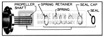
1950 Buick Propeller Shaft Spline Oil Seal
NOTE: Install these parts just before connecting torque tube to torque ball. Do not install parts before rolling axle assembly under car.
- Connect torque tube to universal joint torque ball with bolts and lock washers.
- Connect rear springs to rear axle assembly (left hand threaded bolts) and connect links to shock absorber arms.
- Connect brake hose to brake pipe at frame X member and lock in place with retainer. Connect parking brake cable to bracket on front end of torque tube and to brake cable sheave. Bleed rear wheel cylinders and adjust parking brake as described in paragraphs 8-9 and 8-13.
- Connect radius rod to rear axle. NOTE: Normal weight of car must be on rear springs when tightening radius rod pin nuts so that rubber bushings in rod will be clamped in neutral position.
5-8 REPLACEMENT OF REAR AXLE STRUT ROD
Three bolts attach the rear end of each strut rod to a spring seat welded to outer end of axle housing. The front end of each strut rod is riveted to a bracket welded to front end of torque tube.
Strut rods supplied for service replacement are not drilled for the attaching rivet; therefore, the rivet hole must be drilled to coincide with the hole in bracket after installation and alignment of a strut rod. This cannot be done with rear axle assembly under the car.
- Remove rear axle assembly (par. 5-7).
- Drill through the head of strut rod rivet with a 7/16″ drill; the rivet head has a centering depression for this operation. Drive out rivet with a punch. CAUTION: If rivet head is cut off without drilling, the hole in strut rod and bracket will be distorted.
- Disconnect brake pipe and parking brake cable conduit from strut rod and disconnect strut rod from rear axle.
- Before installation of strut rod, scribe a line on bracket in line with the center of rivet hole. Using a pair of dividers set at 3 inches, locate a center-punch mark on the scribed line exactly 3 inches from center of rivet hole. See figure 5-4 view “A”.
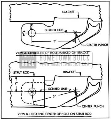
1950 Buick Locating Rivet Hole in Strut Rod
- Install strut rod in normal position without up or down strain at the bracket on torque tube. The top edge of strut rod should be approximately one inch from scribed line on bracket. See figure 5-4, view “B”. It may be necessary to place a shim washer around front bolt between rod and bracket on axle housing to align front end of rod with bracket on torque tube.
- Using a flexible straight edge, scribe a line on strut rod in line with scribed line on bracket. With dividers set at 3 inches and one leg set in center punch mark on bracket, scribe an arc across the line on strut rod. Center punch at intersection of line and arc. See figure 5-4, view “B”.
- At center-punch mark on rod drill a 1/4 inch hole through rod. Follow up with a 1/2 inch and finally a 9/16 inch drill. This will insure alignment of holes in rod and bracket.
- Attach strut rod to bracket with bolt No. 1312923, 1/8 inch lock washer and a thin nut.
- Connect parking brake cable conduit and brake pipe to strut rod, and install rear axle assembly (par. 5-7).
5-9 REPLACEMENT OF AXLE SHAFT, WHEEL BEARING, AND OIL SEALS
1950 Buick Rear Axle Shaft Removal
- Place car stands solidly under rear axle housing so that wheels are clear of floor, then remove rear wheel and brake drum.
- Clean the rear end of chassis, bottom of body, axle housing, wheels and tires, and under rear fenders, removing as much dirt as possible. DO NOT TAKE CHANCES OF GETTING ABRASIVE SUBSTANCES INTO AXLE HOUSING OR BEARINGS.
- Remove cover and drain rear axle housing.
- Remove differential side pinion shaft lock screw, push pinion shaft from differential case, and remove spacer and pinions.
- Push axle shaft inward and drive the horseshoe-shaped lock washer from grooved inner end of axle shaft, using Remover J 1515. See figure 5-5.
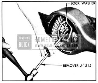
1950 Buick Removing Axle Shaft Lock Washer
- Support the axle shaft while pulling it out of axle housing to avoid damaging the wheel bearing oil seals. CAUTION: Do not pull an axle shaft part way out of housing and allow it to rest on oil seals because this will damage seals; always completely remove shaft from housing.
Replacement of Wheel Bearing and Oil Seals
- After 1950 Buick rear axke shaft removal, disconnect link from shock absorber arm.
- Disconnect brake pipe from wheel cylinder and cover openings in pipe and cylinder with plugs or tape to exclude dirt.
- Remove bolts holding brake backing plate to housing and remove brake assembly. Support brake assembly to prevent injury to the brake cable.
- Remove outer oil seal and roller bearing, then remove inner oil seal, using Remover J 1436. See figure 5-6.
1950 Buick Removing Wheel Bearing and Oil Seal
- Clean and inspect wheel bearing (par. 1-11 and 1-12) including inner race on axle shaft. If inner race requires replacement, remove old race from axle shaft by grinding part way through race and splitting it. CAUTION: Use care to avoid personal injury from flying particles of steel. Press new bearing race into place against shoulder on axle shaft.
- Drive a new inner oil seal squarely and lightly against shoulder in axle housing, using care to avoid distortion of seal.
- Install bearing roller assembly, using care to start it squarely into axle housing by light taps with a brass drift on alternate sides of outer race. Do not drive against the rollers. Drive outer race lightly against the shoulder in axle housing.
- Drive a new outer seal lightly against outer race of bearing, using care to avoid distortion.
- Install brake backing plate with a new gasket between plate and axle housing. Connect shock absorber link to shock absorber arm, and connect brake pipe to wheel cylinder. NOTE: Wheel cylinder will be bled later, after installation of brake drum.
Installation of Axle Shaft
Rear axle shafts are not interchangeable between sides because the right hand shaft is longer than the left.
- Fill rear wheel bearing and space between oil seals with wheel bearing lubricant. Coat leather edges of oil seals with lubricant.
- Support axle shaft as it is inserted into rear axle housing to avoid damaging wheel bearing oil seals.
- Push axle shaft in as far as possible, install horseshoe-shaped lock washer in groove in inner end of shaft, then pull shaft out to seat lock washer in recess in differential side gear.
- Install differential spacer between ends of axle shafts and with both shafts pulled outward as far as possible, check clearance between spacer and shafts with feeler gauges. Total clearance, or axle shaft end play, should be between .000″ and .008″.
- If clearance exceeds .008″, turn spacer 1/4 turn and test clearance again; the spacer has two different thicknesses to permit a selective fit.
- If clearance or axle shaft end play cannot be adjusted to .008″ or less with old spacer, install a new spacer. Service spacers are oversize to permit some take up for wear.
- In some cases, however, it may not be possible to adjust end play to specified limits by installation of oversize spacers; therefore, new bronze thrust washers should be installed between the differential case and the side gears before selecting a spacer of proper thickness to provide not over .008″ end play. See figure 5-30.
- After proper axle shaft end play is obtained, place side pinions and thrust washers in case and push differential side pinion shaft through case, thrust washers, and pinions. Lock shaft in place with lock screw and lock washer.
- Pour a liberal quantity of rear axle lubricant on gears and bearings, and turn rear wheels to work lubricant into all surfaces.
- Install housing cover, using a new gasket and coating bolt threads with white lead to avoid oil leaks. Align filler plug with first bolt hole to right of lower center bolt hole in housing.
This change from straight down position increases oil level to 4 pints.
- Install brake drum and rear wheel. If brake backing plate was removed for bearing replacement (subpar. b), bleed brake wheel cylinder as described in paragraph 8-9.
- Remove car stands so that car is level, then fill housing to filler plug opening with factory hypoid gear lubricant (Group 5.535) and install filler plug securely.
5-10 REMOVAL OF RING GEAR AND CASE, PROPELLER SHAFT AND PINION ASSEMBLIES
NOTE: On all Dynaflow Drive cars and Synchromesh cars equipped with the 3.6 or 3.9 rear axle gear ratio it is necessary to remove the rear axle assembly (par. 5-8) in order to remove the propeller shaft and pinion. This is not necessary on Synchromesh cars having the 4.1 gear ratio because a pinion puller is available, and the propeller shaft spline seal is not used.
Removal of Ring Gear and Case Assembly
- After removal of both axle shafts (par. 5-9), remove differential side gears and thrust washers from case to prevent them falling out and being damaged.
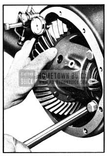
- If ring and pinion gear set has been operating quietly and is to be reinstalled, it is advisable to wash lubricant from between gear teeth and check existing gear lash by means of dial indicator, so that the same lash can be used when parts are reinstalled, to avoid changing gear tooth contact. See paragraph 5-16, steps Sand 9.
CAUTION: Backlash will be reduced when pinion is locked by prying up with a bar if there is excessive pinion lift due to worn bearings. See subparagraph b, step 2, below.
- Mark the differential bearing caps so they can be reinstalled in original positions on the carrier. Interchanging the caps will cause damaged threads because caps are threaded in production while bolted to carrier.
- Remove bearing adjuster locks, loosen one adjuster, support the differential gear and case assembly while removing bearing caps and adjusters, then lift differential assembly and bearing races out of carrier.
- See paragraphs 5-11 and 5-16 for inspection and installation procedures.
Removal and Disassembly of Propeller Shaft and Pinion Assembly
- If ring and pinion gear set has been operating quietly and is to be reinstalled, it is advisable to check the pinion setting after removal of differential case so that the same setting can be used when parts are reinstalled to avoid changing gear tooth contact. See paragraph 5-15.
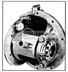
- At this point it may be desirable to test pinion shaft bearing wear without removing pinion shaft. Install 1 1/4″ extension on stem of dial indicator and mount indicator to bear down against center drilling in pinion gear, with indicator stem as near vertical as possible. See figure 5-7.
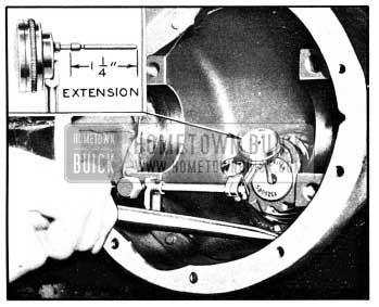
1950 Buick Testing Pinion Bearing Wear
Pry up on pinion gear with bar a number of times while observing indicator reading. A reading in excess of .0015″ indicates that bearing is worn enough to produce noisy gear operation.
- Loosen lock nuts and remove three pinion bearing sleeve lock screws from housing.
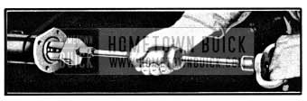
- If gear ratio is 4.1 to 1, the pinion and propeller shaft may be pulled by means of the puller shown in figure 5-8.
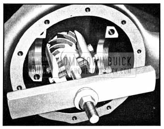
1950 Buick Pinion Puller
This puller will not fit over the pinions of the 3.6 and 3.9 gear sets; therefore, in those jobs the parts must be removed by tapping on the front end of propeller shaft, using a babbit hammer, brass bar, or a protective cap to avoid damaging shaft.
- Remove all pinion bearing shims from propeller shaft and third member housing to prevent damage or loss.
- Mark pinion and propeller shaft so that parts can be reassembled in the same relative position. File or cut off one end of propeller shaft coupling pin and drive out the pin, then pull propeller shaft from pinion using Press J 1292- B. See figure 5-9.
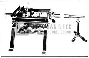
1950 Buick Pinion Press J 1292-B
- Drive up staked section of pinion bearing lock nut with cape chisel and remove nut, gripping pinion shaft on splined end in vise. Do not grip pinion teeth in a vise even though soft jaw liners are used. NOTE: Figure 5-10 shows a bearing lock nut which has been mutilated so that it is unfit for use. The staked edge has been completely cut away instead of being raised , and the hexagon section has been badly burred by use of a pipe wrench.
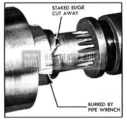
1950 Buick Mutilated Bearing Lock Nut
- Press off pinion front bearing using blocks under outer race of rear bearing, then remove all other parts from pinion shaft. NOTE: The double-row front bearing is preloaded and normally will have a slight drag when installed on pinion. Do not condemn bearing until inspected as specified in paragraph 1-12.
- See paragraph 5-11 for inspection, paragraph 5-14 for assembly, and paragraph 5-15 for installation.
5-11 CLEANING AND INSPECTION OF REAR AXLE PARTS
Cleaning 1950 Buick Rear Axle Parts
Hypoid lubricant is extremely allergic to water and when contaminated with even small quantities of water it has a deteriorating effect on the lubricant. For this reason steam or water should not be used for flushing rear axle assemblies. If used on rear axle parts which are disassembled, extreme care must be used to thoroughly dry all parts before installation.
Gasoline, kerosene, or other distillates are satisfactory for cleaning parts when removed from rear axle housing, if parts are thoroughly dried before installation. They should not be used in an assembled rear axle, however, because if all traces of the cleaner are not removed the fresh lubricant will be contaminated. For this reason, only SAE 10-W or flushing oil is recommended for flushing and cleaning an assembled rear axle.
Wash all parts in clean solvent and wipe dry with clean cloths. Thoroughly wash out interior of rear axle and third member housings and wipe dry with clean cloths. Blow out all dirt with clean, dry air stream.
Inspection of 1950 Buick Rear Axle Parts
- Thoroughly inspect all bearings as described under Bearing Service (par. 1-12). Be particularly careful to inspect rear wheel bearings, including inner race on axle shafts, for corrosion caused by rust and for flat spots on rollers.
- Carefully inspect all gears for scores on face of teeth, for chipped teeth and for excessive wear. Examine ring gear and pinion for improper tooth contact. See figure 5-2.
- Pinion and Propeller Shaft. Check for wear of splines on pinion and in the propeller shaft. Pinion must be tight fit in propeller shaft when parts are assembled. Inspect interior of propeller shaft and if oil is present wash it out thoroughly and dry interior with air.
- Rear Axle and Third Member Housings. A sprung housing should be replaced; straightening is not recommended. A housing must never be heated with a torch as this may produce soft spots in the metal in which fatigue and breakage may develop in service.
Inspect third member housing for: oil leak at torque ball and at flanged joint between torque tube and carrier; cracked torque tube; strut rod brackets broken or cracked at welds; pinion shaft bearing bores galled or worn due to bearing turning in housing; stripped or damaged threads in side bearing pedestals or caps. See paragraph 5-13 for replacement of housing.
Checking Pinion and Rear Bearing Clearance
The desired clearance between pinion and the rear (roller) bearing is .0005″. The maximum allowable clearance for quiet operation is .0014″. Excessive clearance at this point is usually caused by wear of the roller bearing.
Wear of the roller bearing may be checked with a micrometer. Before checking, make certain that bearing is absolutely clean and that micrometer is accurate at zero reading. Measure across the outer race and a roller at four or five points around bearing as shown in figure 5-11, using care to adjust micrometer lightly to high points of roller and race to insure an accurate reading. The micrometer will read .6756″ to .676″ if bearing is satisfactory for use. If reading is less than .6756″ the bearing is worn and should be discarded.
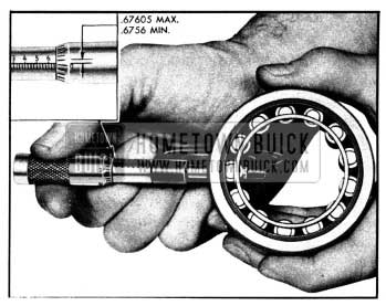
1950 Buick Checking Wear of Pinion Rear Bearing
An alternate method of checking clearance between pinion and roller bearing is shown in figure 5-12.
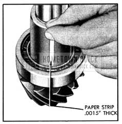
1950 Buick Checking Clearance Between Pinion and Roller Bearing
Obtain a piece of tough paper, such as typewriter “second” sheet which measures .0015″ thick (use micrometer) and cut a test strip 3/16″ wide. Place bearing on pinion about 1/4″ above spacer, insert paper test strip between two bearing rollers and rotate bearing until strip is under one roller. If clearance is satisfactory, the bearing will hang on the paper strip and the paper strip cannot be pulled out. If bearing drops of its own weight, or paper strip can be easily pulled out, the clearance is excessive and bearing should be discarded.
NOTE: If roller bearing is worn excessively, it is quite likely that the double-row front bearing is worn so that it no longer has any preload. Inspect this bearing very carefully and discard if loose or doubtful.
5-12 REPLACEMENT OF RING GEAR, DIFFERENTIAL CASE, OR BEARINGS
Ring gears are furnished for replacement only with the pinions in matched sets. Ring and pinion gear sets and differential cases are furnished separately and also with the ring gear riveted to the case. If case or gear set is satisfactory it should not be discarded because the other part requires replacement.
Replacement of Ring Gear or Differential Case
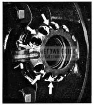
- Center punch all rivet heads on ring gear side, placing marks in center of heads. Drill rivets approximately 1/2″ deep with 1/4″ drill. See figure 5-13.
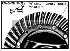
1950 Buick Removal of Ring Gear Rivets
- While supporting flange of differential case on suitable block, insert punch in drilled hole and drive each rivet out; rivets will be easily parted when driven out. NOTE: When rivets are installed, they expand more in the softer case than in the harder ring gear. If rivets are drilled and driven out from case side, metal is sheared from surface of rivets by sharp edge of holes in gear. See figure 5-14. This not only makes removal more difficult but will distort the case flange so that a new gear installed on case will not run true.
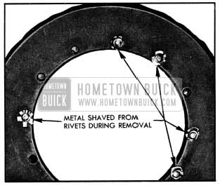
1950 Buick Gear Improperly Removed
- After removal of gear, check machined face of case flange for burrs, particularly around rivet holes. Clean off all burrs with a mill file. Mount case in differential carrier with a dial indicator set to check runout of machined flange surface as shown in figure 5-15. If run-out exceeds .002″, the flange must be trued up in a lathe to not over .002″ run-out.
1950 Buick Checking Run-out of Differential Case Flange
- Check matching numbers on new ring gear and pinion to make sure the two parts have not been mixed with another gear set. See figure 5-23.
- After making sure that surfaces of case flange and ring gear are clean and free of burrs, bolt gear to case using eleven (11) 5/16″x 1 1/2″ bolts with 3/8″ SAE nuts placed in rivet hole counterbores to act as spacers. CAUTION: It is very important to have these parts bolted tight together. Do not use washers over rivet hole counterbores since they will bend and permit parts to separate slightly during riveting operation.
- Mount ring gear and case in differential carrier with a dial indicator set to check run-out of ring gear as shown in figure 5-15A.
1950 Buick Checking Run-out of Ring Gear
If runout exceeds .003″, check for burrs, uneven bolting condition, or distorted case flange.
- When run-out of gear is not over .003″, install new rivets of correct part number which allow 5/16″ of shank for heading. Install rivet in the one open hole from gear side and securely head it up cold, which requires a pressure of eight (8) tons. CAUTION: Excessive pressure may cause rivet to squeeze out between gear and case flange, thereby distorting these parts. Never heat rivets to facilitate heading because hot rivets shrink and become loose in holes during cooling, furthermore, the heads may crack off.
- Remove bolt diametrically opposite new rivet and install another rivet in like manner. Finish riveting by working back and forth across gear, using even pressure on all rivets; do not install rivets consecutively around gear as gear may be drawn to one side and run eccentric.
- After all rivets are installed, recheck for run-out at back of gear. See figure 5-15A. Runout must not exceed .003″.
Replacement of Differential Bearings
- If a differential bearing is to be replaced, or removed from old differential case and installed on new case, pull bearing from case using Bearing Puller J 2241. See figure 5-16. The ends of puller jaws fit into notches in differential case so that pressure can be applied to bearing inner race. Do not pull on rollers.
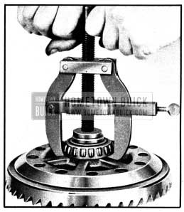
1950 Buick Removing Differential Bearing, Using Puller J 2241
- Before installing differential bearing, examine bearing seat on differential case for burrs or scores. Remove high metal with a mill file and coat seat with engine oil or white lead.
- Install bearing, using Replacer J 2242, which is designed to pilot in the case and bear squarely against bearing inner race. See figure 5-17. Bearing must be pressed tight against shoulder on case.
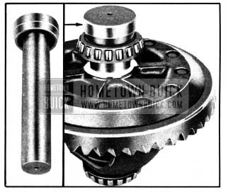
1950 Buick Installing Differential Bearing Using Replacer J 2242
5-13 REPLACEMENT OF THIRD MEMBER HOUSING
The third member housing consists of the torque tube and differential carrier which are flanged and bolted together. The bolted construction is for manufacturing purposes only; torque tube and carrier are not furnished separately for service.
The torque tube and carrier are matched and aligned during manufacture and always must be kept in their original assembly. The tube and carrier should never be disassembled unless it is necessary to install a new gasket to correct an oil leak. The gasket is of special material and substitute material should not be used.
When removing a third member housing, after 1950 Buick rear axle removal, drill through the heads of strut rod attaching rivets with a 7/16″ drill. If rivet heads are cut off with hammer and chisel without drilling, the holes in strut rods and brackets will be distorted.
Third member housings furnished for service replacement are not drilled for rivets in the strut rod bracket. The holes must be drilled after the rear axle housing, third member housing, and strut rods are assembled together. With strut rods in normal position and without up or down strain, drill bracket to match holes in strut rods with 1/2″ drill. Drill through strut rods and bracket with a 9/16″ drill, then install bolts No. 1312923 with 1/8″ lock washers and thin nuts.
5-14 ASSEMBLY AND STRAIGHTENING OF PINION AND PROPELLER SHAFT
Installation of Pinion Bearing Oil Seal – If Required
In cases where oil seeps from the rear axle into the torque tube or propeller shaft and may pass a defective propeller shaft spline oil seal and enter the transmission, correction may be affected by installation of a pinion bearing oil seal. The oil seal and a special pinion bearing lock nut is furnished in a kit for service installation under Group 5.445.
- In order to check the oil seal for proper fit in differential carrier the tool shown in figure 5-18, view C must be prepared locally. Note that oil seal is secured to end of tool by the screw and washer.
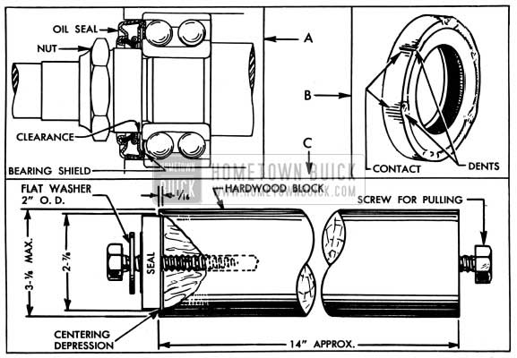
1950 Buick Installation Details for Pinion Bearing Oil Seals
- With seal on tool as shown, drive seal lightly into carrier bore-do not use excessive force. If seal will not start into the bore, slightly reduce outside diameter with emery cloth or by light filing. Thoroughly wash off emery dust or filings to avoid contamination of bearings.
- After seal has been lightly driven into carrier bore, carefully remove it and examine outer surface. If fit is correct the surface will bear light scratches spaced evenly all the way around. In this case final installation can be made without further fitting.
- If the oil seal slips easily into carrier bore and does not have evenly spaced scratches as noted above, it must be fitted for better contact and sealed at final installation.
- To expand the seal for better fit, use a light hammer to carefully dent the bead on rear side at six evenly spaced points. See figure 5-18, view B. CAUTION: Original bead height must be retained over most of the seal since the bead spaces seal from front bearing shield to prevent interference. See figure 5-18, view A.
- After denting seal, fit it into carrier bore as previously explained. When removed, the outer surface should have evenly spaced scratches at all dents. See figure 5-18, view B.
- When seal has been properly fitted to carrier bore, place it on the pinion bearing lock nut with inner leather seal pointing away from hex of nut. See figure 5-18, view A.
- Assemble pinion and propeller shaft as described below. If the seal was fitted to carrier bore by denting the head it will be necessary to apply sealing compound, after pinion shims have been selected and final installation is being made. Apply a light coat of Permatex No. 2 to outer surface of oil seal and allow to dry until gummy (at least 30 min.) before final installation. Avoid excessive use of sealer, which may get between shims and affect the pinion location.
Assembly of Pinion and Propeller Shaft
NOTE: Before assembly make certain that interior of propeller shaft is free of oil and is clean and dry. Any foreign material in propeller shaft will throw it out of balance and . cause vibration.
- Install parts on pinion shaft in the following order: rear bearing spacer, two rear bearings (roller), bearing lock sleeve with thick end toward spline, front bearing (ball) with shielded side toward spline. See figure 5-19. Press front bearing solidly against shoulder on pinion shaft, using a tube of proper size to bear against inner race only. NOTE: Bearing may be brinnelled if driven into place.
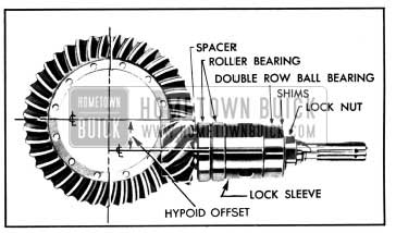
1950 Buick Gear Set with Bearings and Lock Sleeve
- Install bearing lock nut with thin side toward spline. While gripping splined end of pinion in vise, tighten nut to a minimum of 150 ft. lbs. torque; nut must hold bearing tight against shoulder on pinion. Do not grip pinion teeth in vise even though soft jaw liners are used. Stake thin edge of nut down into notch in pinion.
- When assembling pinion and propeller shaft the splined joint must be sealed to prevent lubricant from entering propeller shaft and causing an unbalanced condition. The factory uses Presstite Sealer, an aluminum base plastic material, which may be obtained from the Presstite Engineering Company, St. Louis, Missouri.
Permatex or white lead may be substituted but these are not as efficient.
- Dip end of pinion into sealer, then press pinion into propeller shaft until coupling pin holes are aligned, using Press J 1292-B. See figure 5-9. Pinion must not be a loose fit in propeller shaft. Install a new coupling pin and solidly rivet both ends.
IMPORTANT: Whenever a pinion and propeller shaft are assembled together the complete assembly must be checked for straightness regardless of whether new or original parts are assembled. See following subparagraphs.
Straightening Pinion and Propeller Shaft Assembly, Using Fixture
The pinion and propeller shaft assembly may be quickly and satisfactorily checked and straightened by means of the fixture shown in figure 5-20.
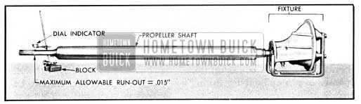
1950 Buick Checking Propeller Shaft in Fixture
This fixture should be made locally, using a 1949 or 1950 differential carrier. A special N.P.N. carrier (without torque tube) may be ordered for this purpose from the Buick Service Department, Flint, Michigan. Details of the carrier supports are given in B.P.S. 2.214 and in figure 5-20 of the 1948-49 Buick Shop Manual.
- Mount the pinion and propeller shaft assembly in the fixture, being sure to tighten pinion bearing lock screws evenly and securely to press pinion front bearing solidly against shoulder.
- Mount a dial indicator on a rod fastened to a block of sufficient weight to hold the indicator button firmly against the ground portion of the propeller shaft, just to the rear of the splines as shown in figure 5-20.
- Turn the shaft by hand from the pinion end and note the amount of run-out as shown by the indicator. The total indicator reading should not exceed .015″.
- If the reading exceeds .015″, turn shaft to high point on indicator and force end of shaft downward by hand sufficiently to spring it to within .015″ run-out. Recheck for run-out after each springing operation.
Straightening Pinion and Propeller Shaft Assembly, Using V-Blocks
If the fixture shown in figure 5-20 is not available, the pinion and propeller shaft may be checked and straightened using V-blocks or rollers and a dial indicator.
- Support the assembly on V-blocks placed under the machined section just to rear of splines at “A” and under the rear (roller) bearing at “B”. See figure 5-21.
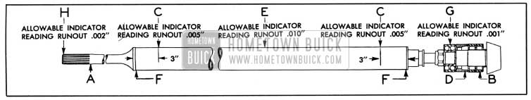
1950 Buick Propeller Shaft Run-out Specifications
- Mount a dial indicator so that readings for run-out can be taken successively at points “C” located 3″ from each end of shaft tube, point “E” at middle of shaft tube, point “G” at front (ball) bearing, and Point “H” at front end of splines. When checking points “C” and “E”, care must be taken not to permit the seam or hollow spots on tube to give a “bounce” to indicator and thus show a wrong indicator reading.
- Check run-out at points “C” first. If total indicator reading is .005″ or less, the shaft is OK at these points. If run-out exceeds .005″, support the shaft at “A” and “D” (under lock sleeve) and exert pressure against high side of shaft at point “F” located on end of shaft tube where run-out exits. Use steady pressure and not shock blows to spring shaft as required to bring run-out at points “C” within .002″.
- Check run-out at point “E” after correcting any run-out at points “C”. If run-out at “E” exceeds .010″ total indicator reading, support the shaft at points “F” and exert steady pressure against high side of shaft as required to bring run-out within .010″.
- Check run-out at point “G” after correcting run-out at points “C” and “E”. If run-out at “G” exceeds .001″ total indicator reading, support the shaft at points “A” and “D” and exert steady pressure at the rearward point “F” on high side of shaft.
- Finally, re-check run-out at points “C”, “E” and “G” to make sure that run-out is within specified limits at all points. The run-out at point “H” should then be within .002″ total indicator reading. More than .002″ run-out at “H” will cause rapid wear of universal joint bushing and possible leakage of oil from transmission into rear axle.
5-15 INSTALLATION AND ADJUSTMENT OF PINION AND PROPELLER SHAFT
Installation of Pinion and Propeller Shaft
Before installation of pinion and propeller shaft assembly make certain that interior of rear axle and third member housings are absolutely clean and dry. Also make certain that parts to be installed are clean and that pinion bearing shims are not damaged.
- If the original third member housing and pinion shaft are being used, place the original number and thicknesses of pinion bearing shims over propeller shaft against front bearing, to maintain original setting of pinion.
- If a new pinion is being installed, change the total thickness of shims by the difference between the old pinion and new pinion setting marks as explained in subparagraph b, below. For example: if old pinion is marked “+3″ (plus 3) and new pinion is marked”-2″ (minus 2), total thickness of shims installed should be .005″ greater than shims removed.
NOTE: Shims furnished with new gear sets are for use as required in adjustment and are not necessarily of correct total thickness.
- Lubricate both pinion bearings thoroughly with rear axle lubricant which should also be used to hold shims against front bearing. As pinion and propeller shaft assembly is inserted into third member housing, turn pinion front bearing outer race so that the ball loading groove will be straight up, to prevent oil running through into torque tube.
- As the pinion rear bearing enters third member housing, place Pinion Bearing Spacer J-1192-B, (1/4″ thick) between bearing and pinion gear so that bearing can be pushed into place without binding against spacer on pinion shaft. See figure 5-22.
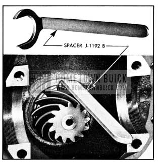
1950 Buick Use of Pinion Bearing Spacer J 1192-B
- Lightly tap the pinion forward with a brass drift until the holes in pinion bearing lock sleeve align with tapped holes in carrier, then install the three sleeve lock screws. Tighten each lock screw a little at a time until lock sleeve and pinion front bearing are solidly seated and screws are uniformly tightened to 35-40 ft. lbs. torque. Tighten lock nuts to 15-20 ft. lbs. torque; excessive tightening of nuts may withdraw lock screws sufficiently to allow end play of pinion bearing. Remove Spacer J 1192-B.
- Regardless of whether original or new parts affecting pinion setting are installed, check pinion setting with gauge as described in the following subparagraphs.
Pinion Setting Marks and Setting Gauges
All Buick ring and pinion gear sets are selectively matched for quiet operation and proper tooth contact. After matching, a serial number is etched on one tooth of pinion and on rear face of gear to aid in keeping matched parts together. See figure 5-23. Parts having different matching serial numbers must never be used together.
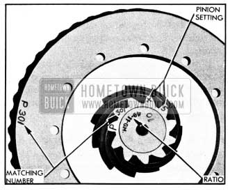
1950 Buick Ring and Pinion Gear Markings
Ring and pinion gear sets are matched in a special test machine which permits adjustment of pinion depth in ring gear until a point is reached where quiet operation and proper tooth contact under load is obtained. At this point, the setting of pinion with reference to centerline of ring gear is indicated by the machine. This setting may vary a few thousands of an inch from the design or “nominal” setting due to allowable variation in machining the parts.
In order to make it possible to duplicate the matching setting of the pinion when the gear set is installed in a third member housing, the pinion is marked to indicate this setting with reference to the “nominal” setting. The amount of thousandths of an inch plus or minus the “nominal” setting is etched on the small end of one pinion tooth. See figure 5-23. When a pinion is marked “+” (plus) it means that the pinion must be set at a distance from the centerline of the ring gear equal to the “nominal” setting plus the amount indicated on pinion tooth. When a pinion is marked”-” (minus) it means that the pinion must be set at a distance equal to the “nominal” setting minus the amount indicated on pinion tooth.
Pinion Setting Gauge J 681-A or J 2197 is required in order to measure the pinion setting after it is installed in a third member housing.
Pinion Setting Gauges J 681-A and J 2197 are identical except for the markings of the micrometer section, as described below. Either tool consists of a micrometer gauge, a checking gauge, an adapter for use with hypoid gear sets, and a clamp to hold the adapter in position. The micrometer gauge has sliding stepped collars so that gauge can be used in all models. The checking gauge should be used to test the accuracy at zero of the micrometer gauge before using the gauge. See figure 5-24.
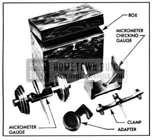
1950 Buick Pinion Setting Gauge
Pinion Setting Gauge J 681 A
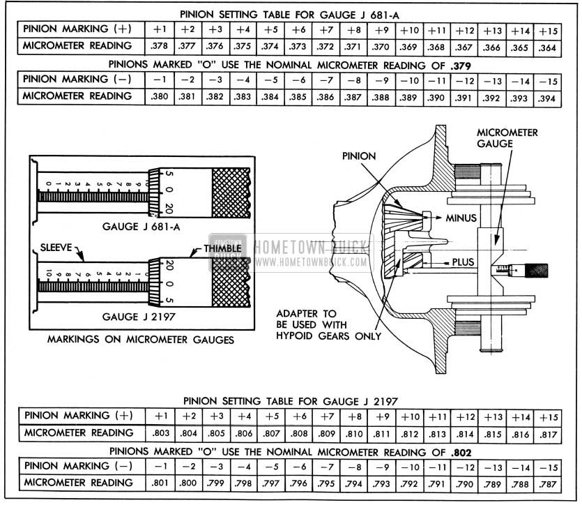
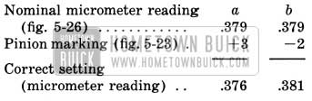
This gauge has the thimble and sleeve of the micrometer marked exactly like a standard micrometer. See figure 5-26.
1950 Buick Pinion Setting Tables for Gauge J 681-A and Gauge J 2197
When the thimble is turned clockwise to extend the spindle, the reading becomes less. Consequently, when this gauge is used to measure depth of a pinion marked”+” (plus), the amount marked on the pinion tooth must be subtracted from the “nominal” micrometer reading. Likewise, if pinion is marked “-” (minus), the amount marked on the pinion tooth must be added to the “nominal” micrometer reading.
1950 Buick Pinion Setting Gauge J 681 A
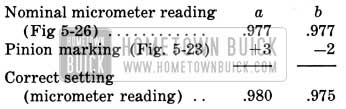
Pinion Setting Gauge J 2197
This gauge has the thimble and sleeve of the micrometer marked the opposite of a standard micrometer. See figure 5-26. When the thimble is turned clockwise to extend the spindle, the reading becomes greater. Consequently, when this gauge is used to measure depth of a pinion marked”+” (plus) the amount marked on the pinion tooth must be added to the ‘1nominal” micrometer reading. Likewise, if pinion is marked “-” (minus), the amount marked on the pinion tooth must be subtracted from the “nominal” micrometer reading.
1950 Buick Pinion Setting Gauge J 2197
Checking Pinion Setting with Gauge
- Before Pinion Setting Gauge is installed, check the ends of pinion teeth and stone off any burrs; also rub stone over etched markings to remove high spots. The gauge adapter must seat flatly and firmly against ends of pinion teeth in order to secure an accurate micrometer reading.
- Install adapter with clamp, and the micrometer gauge as shown in figure 5-25.
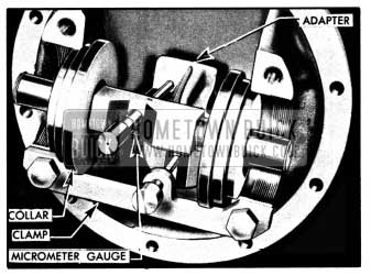
1950 Buick Pinion Setting Gauge Installed
The adapter must be firmly held against the pinion by the clamp. The micrometer gauge must be firmly seated in the differential bearing seats in carrier, with micrometer spindle at 90 degrees to surface of adapter.
- The pinion setting is obtained by adjusting micrometer until the spindle just touches the adapter, then reading the micrometer. NOTE: Swing the micrometer spindle up and down slightly while adjusting, to feel the exact point at which it contacts the adapter.
- If the old ring and pinion gear set is being reinstalled and it has been in use long enough to establish a wear pattern on teeth, the original pinion setting found before removal (par. 5-10, b) should be maintained to avoid changing tooth contact.
If the ring and pinion gear set is new, or has not been in use long enough to establish a wear pattern on teeth, the micrometer reading should be within .001″ (plus or minus) of the reading given under the proper pinion marking in figure 5-26. Note that figure 5-26 gives one pinion setting table for Gauge J-681-A and another for Gauge J 2197 since the micrometers are not marked alike on both gauges.
- If pinion setting is not as specified, adjust as described below.
Adjustment of Pinion
The pinion setting is adjusted by changing the total thickness of the pinion bearing shims which are located between the pinion front bearing and the shoulder in third member housing.
- Remove pinion and propeller shaft assembly (par. 5-10, b).
- Remove all pinion bearing shims from shaft or in third member housing, wipe shims dry, and measure their total thickness with a micrometer, or with a dial indicator set to bear against a flat surface.
- Increase or decrease total thickness of shims as required to obtain proper pinion setting, by using a different combination of shims. These shims are furnished in thicknesses ranging from .010″ to .019″ in increments of .001″, so that any total thickness may be obtained by using a combination of different shims.
- Install pinion and propeller shaft assembly with new combination of shims and be sure to tighten the three bearing sleeve locks uniformly to 35-40 ft. lbs. torque, and lock nuts to 15-20 ft. lbs. torque.
- Check pinion setting with gauge. Setting should be within .001″ plus or minus, of required micrometer reading.
5-16 INSTALLATION AND ADJUSTMENT OF RING GEAR AND CASE ASSEMBLY
- Before installation of ring gear and case assembly make sure that differential bearing seats in carrier pedestals and caps are clean and free of burrs. Remove any burrs which might prevent bearings or bearing caps from seating properly.
- Place outer races on differential bearings but do not oil bearings as this would interfere with bearing adjustment. Install gear and case assembly in carrier and slide bearing adjusters into position so that threads are engaged in threads in carrier pedestal.
- Install bearing caps with bolts, making sure that caps are installed in original positions as marked before removal. Turn bearing adjusters to engage threads in caps. Tighten cap bolts to 20 ft. lbs. torque then loosen all four bolts 1/4 turn.
- Using Adjuster Wrench J 1365 (fig. 5-27) turn adjusters as required to set ring gear lash at approximately .008″ to .012″, with both adjusters in firm contact with bearings.
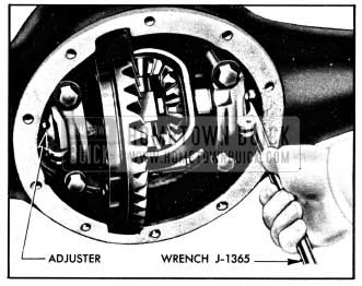
1950 Buick Adjusting Differential Bearings
CAUTION: Do not use punch and hammer to turn adjusters as adjusters will be distorted (see fig. 5-28) and proper bearing adjustment cannot be obtained.

1950 Buick Adjuster Mutilated by Wrong Tool
- Back off one adjuster (preferably left) while observing bearing rollers and outer race, until rollers and race just stop turning, then tighten adjuster 4 to 5 notches to properly seat bearings and adjusters.
- Slowly back off adjuster until bearing outer race just stops turning. Recheck for this “free position” at least once to make sure of proper position.
- From the “free position” tighten the adjuster 21/2 to 3 notches to pre-load the bearings, then tighten all 4 bearing cap bolts to 90-100 ft. lb. torque.
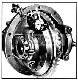
- Mount dial indicator as shown in figure 5-29.
1950 Buick Checking Back Lash with Dial Indicator
Use a small button on indicator stem so that contact can be made off the edge of tooth. Set dial indicator so that indicator stem is as nearly in line with gear rotation as possible. If stem bears against edge of tooth, or stem is at considerable angle to the line of gear rotation, a false indication of backlash will be obtained.
- Lock the pinion with hammer handle or small bar and move ring gear through backlash range while observing movement of indicator hand. Check backlash in this manner at three or four points around ring gear to determine points of minimum backlash.
- The desired backlash .is .008″ to .010″; however, backlash at minimum point should not be less than .008″ and at maximum point should not exceed .012″. If original ring and pinion gear set is being reinstalled, the original lash of gears should be maintained to avoid changing tooth contact.
- If backlash is not within limits specified above, move ring gear to right or left as required to secure proper backlash. To move ring gear, loosen all bearing cap bolts 1,4 turn; loosen one notch on bearing adjuster on side toward which gear is to be moved and tighten one notch on opposite adjuster. When one adjuster is loosened always tighten opposite adjuster the same amount in order to maintain the bearing preload adjustment made in step 7 above. One notch change of both adjusters in the same direction will change backlash .004″ to .005″. The offset ends of bearing adjuster locks permit half-notch adjustments.
- Always tighten all bearing cap bolts to 90-100 ft. lbs. torque after adjusters have been moved and recheck backlash with dial indicator as described in step 8 above. When backlash is properly set, install both bearing adjuster locks.
- Install differential side gears and thrust washers in case. See figure 5-30.
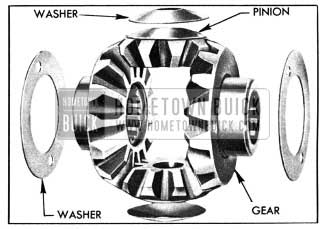
1950 Buick Differential Side Gears, Pinions, and Thrust Washers
- Inspect rear wheel bearings and oil seals and replace if necessary. Lubricate bearings and install axle shafts (par. 5-9).
IMPORTANT-Break-in with New Gears
When new gears are installed in a rear axle assembly by the dealer, the car owner must be cautioned to operate the car in the same manner as he would a new car, for a reasonable length of time until the new gears have run in smoothly.New gears may be scored during break-in by sustained high speed driving, harsh use of clutch causing rear wheels to spin, and by coasting at high speed with clutch disengaged and engaging clutch suddenly.
Leave A Comment
You must be logged in to post a comment.