SECTION-10-F 1950 BUICK IGNITION SYSTEM
10-42 THE 1950 BUICK IGNITION SYSTEM COMPONENTS
The 1950 Buick ignition system consists of the 1950 Buick ignition switch, 1950 Buick ignition coil, 1950 Buick ignition distributor, 1950 Buick spark plugs, and the low and high tension wiring. Electrical energy is obtained from the battery while cranking and during idle speeds, and from the generator at higher speeds. These supply circuits must be considered part of the 1950 Buick ignition system.
1950 Buick Ignition Switch
The 1950 Buick ignition switch has three positions; “LOCK”, “ON”, and “OFF”. When in the “LOCK” position with key removed, the ignition is turned off and the switch is locked. When in the “ON” position the ignition is turned on, and in the “OFF” position the ignition is turned off, with or without the key in place in either position.
The 1950 Buick ignition switch has three terminals. One terminal is connected to the battery; the other terminals connect to the 1950 Buick ignition coil, accelerator vacuum switch, gas gauge, signal lights and accessories. See wiring circuit diagram in Section 10-J. The terminals are protected and made inaccessible for unauthorized bridging around the 1950 Buick ignition switch by a metal shield attached to the instrument panel.
1950 Buick Ignition Coil
The 1950 Buick ignition coil is mounted on the engine push rod cover close to the 1950 Buick ignition distributor.
The coil is oil filled and hermetically sealed so that it will not absorb moisture. The positive (+) terminal is connected to the 1950 Buick ignition switch and the negative (-) terminal is connected to the primary terminal of the distributor. The secondary (high tension) terminal is connected by a short cable to the center terminal in distributor cap.
The coil mounting bracket provides a means of mounting a radio capacitor. The capacitor lead must always be connected to the positive (+) terminal of the 1950 Buick ignition coil.
1950 Buick Ignition Distributor
The 1950 Buick ignition distributor is mounted on the right side of engine crankcase and is driven directly from the camshaft through steel gears which are automatically lubricated by the engine oiling system. The gear thrust is upward against a special bronze thrust washer.
The distributor is of the single contact type with an 8-lobe cam. High speed operation is obtained by an especially light contact breaker arm and a high speed cam. Maximum operating efficiency of the engine is obtained under all speed and load conditions by the centrifugal advance mechanism and the vacuum advance mechanism built into the distributor.
1950 Buick Spark Plugs
AC type 46-X spark plugs were adopted as standard equipment shortly after production started and are recommended for all replacements on 1950 engines. Type 46-X is a slightly cooler plug than type 48 used at start of production. Both types have aluminum oxide insulators, 14 M/M threads, and 13/16″ hex shells.
1950 Buick Radio Suppressor and Capacitor
If car is equipped with a radio, a suppressor is installed in the center high tension terminal of the distributor cap. A capacitor is mounted on the side of ignition coil and connected to the positive (battery) terminal of coil.
In most instances, factory approved radios do not require suppressors on the spark plugs. The use of radio spark plugs and splice type suppressors is not recommended.
An additional capacitor must never be connected to the distributor terminal as this will cause excessive pitting of breaker points or engine missing.
10-43 OPERATION OF 1950 BUICK IGNITION SYSTEM
1950 Buick Ignition Operating Circuits
To clarify operating principles as well as to simplify the process of tracing troubles, the parts of the 1950 Buick ignition system should be understood to provide two separate and distinct circuits, as follows:
- The Primary Circuit carries the low voltage current supplied by the battery or generator. In addition to these sources of electrical energy, the primary circuit contains the 1950 Buick ignition switch, primary winding of the ignition coil, distributor contact points, condenser, and all connecting low tension wiring.
- The Secondary Circuit carries the high voltage surges produced by the ignition coil, which result in high voltage spark between the electrodes of the spark plugs in engine cylinders. This circuit contains the secondary winding of the ignition coil, coil to distributor high tension lead, distributor rotor and cap, ignition cables, and spark plugs.
Cycle of Operation
When the 1950 Buick ignition switch is turned on and the distributor contact points are closed, battery or generator current flows through the primary winding of the coil and through the contact points to ground. This flow of current through the primary winding of the coil produces a magnetic field around the coil windings and thereby stores electrical energy in the coil.
When the contact points are separated by the revolving distributor cam, the primary circuit is broken. The condenser absorbs the current which tends to surge across the gap as the points separate, thereby producing a sharp break in the flow of current. If the flow of current were not sharply broken it would form an arc which would burn the points badly and would also drain away most of the energy stored in the coil. There would be insufficient energy left in the coil to produce the necessary high voltage surge in the secondary circuit.
The very rapid change in strength of the magnetic field when the primary circuit is sharply broken causes a high voltage to be induced in every turn of both the primary and secondary windings. In the primary winding the voltage may reach a value as great as 250 volts, resulting in further charging of the condenser. In the secondary winding the voltage may reach a value of 25,000 volts, although the value is usually 4,000 to 18,000 volts, depending on operating conditions.
The high voltage surge produced in the secondary winding of the coil travels through the cable to the center of distributor cap, through the rotor to the adjacent distributor cap segment from which it is conducted to the proper spark plug by the ignition cable. The high voltage surge jumps the gap between the insulated center electrode and the grounded side electrode of the spark plug, thus producing the spark required to ignite the charge in the selected combustion chamber of the engine.
As the spark appears at the spark plug gap the energy in the coil begins to drain from the coil through the secondary circuit, thus sustaining the. spark for a small fraction of a second. During this interval the condenser discharges back through the primary circuit, producing an oscillation of the current flow in the primary circuit during the brief instant that . is required for the primary circuit to return to a state of equilibrium. Note particularly that the ignition condenser does not discharge until after the spark has occurred at the spark plug gap.
The sequence of action described above is repeated as each lobe of the distributor cam moves under and past the rubbing block on the contact breaker arm to cause the contact points to close and open.
Control of 1950 Buick Spark Timing
The timing of the spark with respect to piston position in the cylinder must vary in accordance with operating conditions if best engine performance is obtained. The spark advance for obtaining satisfactory idling should be as low as possible. At high speed, the spark must occur earlier in the compression stroke in order to give the fuel-air mixture ample time to ignite, burn and deliver its power to the piston as it starts down on the compression stroke.
Under part throttle light load operation, a smaller amount of fuel-air mixture (by weight) enters the cylinder so that the mixture is less highly compressed. Under this condition, advancing the spark permits fuller utilization of the fuel-air charge. During acceleration or on heavy loads (wide open throttle) the spark advance required to develop the maximum power of the engine is considerably less than that required for light loads.
Control of spark timing to satisfy these constantly changing operating requirements is obtained in three ways, as follows:
- Initial, manual setting of distributor is made so that contact points open at a specified position of piston, as indicated by a timing mark on flywheel. See 1950 Buick Ignition Timing (par. 10-47).
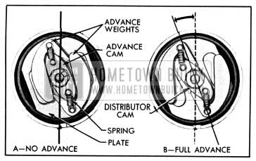
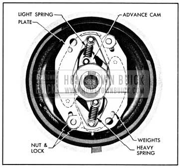
- Centrifugal advance is governed by speed of engine. The centrifugal advance mechanism built into the distributor consists of an advance cam which is integral with the distributor cam, a pair of advance weights, two springs, and a weight base plate which is integral with the distributor shaft.
At low speeds the springs hold the advance weights as shown in figure 10-57, view A, so that there is no additional spark advance and the spark occurs in accordance with the initial manual setting of distributor. As speed increases, centrifugal force causes the advance weights to throw outward and push the advance cam, thus rotating the distributor cam ahead of the distributor shaft. This causes the distributor cam lobes to open and close the contact points earlier in the compression stroke so that the spark is advanced. See figure 10-57, view B.
1950 Buick Centrifugal Advance Mechanism
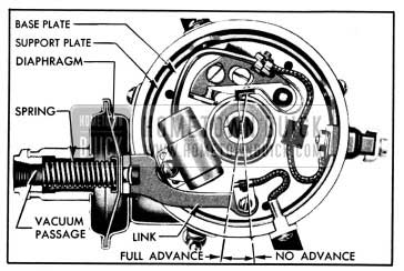
- Vacuum Controlled Advance is governed by manifold vacuum during part throttle operation. The contact points are mounted on a base plate which is supported by three bakelite buttons or bearings upon a stationary support plate in distributor housing. The base plate is held to the support plate by a retainer washer seated in a groove of base plate hub, which serves as a bearing to permit the base plate to rotate on the support plate. The base plate and attached contact points can be rotated around the distributor cam by the link of the vacuum control mounted on the side of distributor housing. See figure 10-58.
1950 Buick Vacuum Advance Mechanism
The vacuum control contains a spring loaded diaphragm. The spring-loaded side of the diaphragm is connected by a pipe to an opening in the carburetor barrel. This opening is on the atmospheric side of the throttle valve when the throttle is in idling position so that there will be no vacuum to operate the advance mechanism.
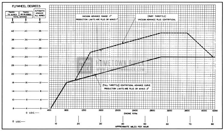
When the throttle valve is opened equivalent to approximately 18 MPH, the vacuum at the opening is sufficient to act on the control diaphragm, causing it to compress the spring and to rotate the breaker plate in a clockwise direction. This moves the contact points so that the distributor cam lobes open the points earlier in the compression stroke. The amount of throttle opening determines, in part, the amount of intake manifold vacuum and thus the amount of spark advance obtained. The advance obtained by the vacuum control is added to the advance obtained by the centrifugal advance mechanism, shown in figure 10-59.
1950 Buick Distributor Spark Advance Chart
10-44 PERIODIC INSPECTION OF 1950 BUICK IGNITION SYSTEM
The best assurance of obtaining maximum service with minimum trouble from the 1950 Buick ignition system is to follow a regular inspection procedure at periodic intervals and to correct any sub-normal conditions disclosed by the inspection. Lubrication of the distributor is covered under Periodic Lubricare Instructions (par. 1-1 and 1-2). The following inspection procedure will disclose any sub-normal condition in 1950 Buick ignition system that requires correction.
Battery and Primary Circuit Wiring
- Check battery and cables to make sure 1950 Buick ignition system has a dependable source of energy (par. 10-17).
- Check primary circuit wiring connections at cranking motor solenoid switch, charge indicator, No. 1 terminal on light switch, ignition switch, ignition coil and distributor. If any connections are loose, disconnect and clean terminals thoroughly, then connect and tighten securely. Check wiring insulation and repair any breaks with tape.
Centrifugal and Vacuum Advance Mechanisms
- Remove distributor cap. Turn the rotor in a counterclockwise direction until advance weights are fully extended, release rotor and allow springs to return weights to retard position. Repeat several times. If springs do not return weights to stop without sticking, or there is excessive free movement of rotor and cam in the retard position, remove distributor for correction.
- Rotate breaker plate by pushing against condenser and note whether spring in vacuum control unit returns breaker plate to full retard position.
Contact Points, Condenser, and Connections
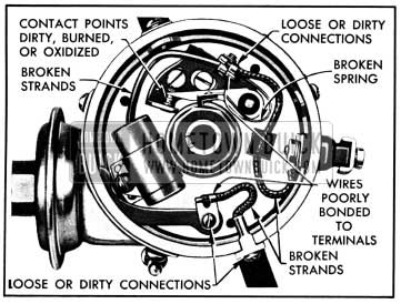
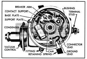
- Check contact point and condenser connector leads and breaker plate ground lead for loose or broken connections. Inspect for broken breaker arm spring and loose or broken rubbing block. See figure 10-60.
1950 Buick Points of Resistance in Primary Circuit of Distributor
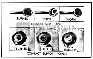
1950 Buick Worn Out Contact Points
- Burned points may be caused by a defective condenser. Test the condenser (par. 10-50).
- Burned points may be caused by insufficient contact point opening. This item will be checked later.
- Oil vapors may be getting into the distributor and depositing on contact surfaces of points. This causes arcing and rapid burning of contact points. Oil vapor entering distributor usually produces a smudgy line on breaker plate under the points.
- High voltage, or any other condition in electrical system which causes excessive flow through contact points results in a blue scale forming on point surfaces. Check condenser circuit for high series resistance (par. 10-50). Check voltage and current regulator (par. 10-29).
- A radio capacitor connected to distributor terminal will cause excessive pitting of contact points. Capacitor should be connected to the positive (battery) terminal of coil.
1950 Buick Distributor Cap and Rotor
- Wipe out distributor cap with a clean cloth and inspect it for chips, cracks, and carbonized paths which would allow high-tension leakage to ground. Such defects require replacement of cap. Clean any corrosion from surfaces of terminal segments inside the cap. DO NOT USE EMERY CLOTH OR SAND PAPER. If segments are deeply grooved the cap should be replaced.
- Pull cables from terminal sockets in distributor cap and coil and inspect sockets for corrosion. Clean corroded sockets, using Terminal Cleaner KM0-230 or a stiff wire brush. Blow all dust out of sockets and inside of cap.
- Replace rotor if badly burned.
- Apply several drops of oil to wick in top of distributor cam, then install rotor and cap.
1950 Buick Ignition Coil
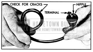
Faulty ignition coil operation can be caused by moisture, grease or dirt on the coil cap. Wipe off coil with clean cloth. Check the high tension cable connection to make sure it is clean and tight and that the cable nipple is properly placed over the secondary terminal.
Also make sure that cable is tight in radio suppressor in distributor cap, if suppressor is used at this point. If coil is suspected of being faulty it should be tested before being replaced (par. 10-49).
1950 Buick Spark Plugs and 1950 Buick Ignition Cables
- Remove all spark plugs for cleaning and adjusting. See paragraph 10-48.
- Wipe ignition cables with cloth moistened with kerosene, and wipe dry. Bend cables to check for brittle, cracked, or loose insulation. See figure 10-62.
1950 Buick Inspection of Ignition Cable
Defective insulation will permit missing or cross-firing of engine, therefore defective cables should be replaced.
1950 Buick Ignition Timing
After cleaning, adjustment, or replacement of contact points, or removal of distributor, the 1950 Buick ignition timing must be checked and adjusted. Even if contact points or distributor have not been disturbed during inspection, the timing should be checked. See paragraph 10-47.
10-45 1950 BUICK DISTRIBUTOR CONTACT POINT ADJUSTMENT
Distributor contact points adjustment must always be made after cleaning or replacement of contact points, and should be checked at periodic inspection because the opening decreases with wear of rubbing block and cam. The contact point opening when breaker arm rubbing block is on highest points of distributor cam lobes must be maintained between .0125″ and .0175″.
If the point opening is less than .0125″, the primary current may arc across the opened points instead of breaking sharply. This would cause the stored energy to be drained from the coil so that it would not produce the required high voltage surge in the secondary winding. If the point opening is more than .0175″, the contact points may not remain closed long enough at high speed to permit sufficient flow of current through the primary winding. The coil would not be strongly magnetized and, therefore, could not produce the required high voltage surge in the secondary winding. In either case, the spark produced at spark plugs would be too weak to fire the fuel-air charge in the cylinders.
Before contact points are replaced or checked for point opening it is advisable to check for any fluctuation under operating conditions, as described in subparagraph a below. Contact point opening may fluctuate under operating conditions due to eccentric movement of the breaker plate or excessive runout of distributor cam. The result is usually uneven performance of the engine at low speeds. This condition will not be corrected by replacement or adjustment of contact points only.
The three methods in general use for checking contact point opening are discussed in the following subparagraphs, and the adjustment procedure is given in subparagraph b.
- Dial Indicator (subpar, b)
- Feeler Gauge (subpar. c)
- Cam Angle Meter (subpar. d)
Checking Contact Point Fluctuation Under Operating Conditions
Before checking or adjusting contact point opening it is advisable to check contact point fluctuation under operating conditions. If points fluctuate beyond allowable limits this condition must be corrected before point opening can be properly set. Contact point fluctuation may be checked with a cam angle meter; however, its use for checking actual point opening is not recommended (see subpar. d).
- With cam angle meter connected in accordance with the manufacturer’s instructions, run engine at 450 RPM and note meter reading.
- Slowly increase engine speed to 2000 RPM and note meter reading,. then release throttle quickly and allow engine to return to idling speed. Repeat several times.
- The meter reading should remain constant within 2 degrees when engine is slowly accelerated and rapidly decelerated between 450 and 2000 RPM. If reading varies more than 2 degrees or the meter hand suddenly jumps several degrees, it indicates fluctuating contact point opening.
- Disconnect pipe from vacuum control unit and repeat the test. If meter reading remains steady within 2 degrees with vacuum advance mechanism not operating, the fluctuation was caused by eccentric action of breaker base plate which supports the contact points. Eccentric action of base plate would be due to improper tension, permitting plate to tip, or to excessive clearance at base plate center bearing.
- If meter reading still varies with vacuum advance mechanism not operating, the distributor cam is worn unevenly or has excessive run out.
- See paragraph 10-51 for correction of base plate tipping or cam run-out.
Checking and Adjusting Contact Points with Dial Indicator
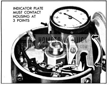
Distributor Point Opening Indicator J 3955 (fig. 10-63) is recommended for checking and adjusting contact point opening.
1950 Buick Indicator J 3955 Installed on Distributor
It locates upon the contact support (stationary point), shows the exact point opening regardless of condition of points or breaker arm rubbing block, and directly indicates point opening as the contact support is moved during adjustment.
- Before installing Indicator J 3955 make certain that 1950 Buick ignition switch is in “LOCK” or “OFF” position. If 1950 Buick ignition switch is turned “ON,” current will pass through the indicator and possibly damage it.
- Remove distributor cap and rotor.
- Depress indicator stem so that attached finger will clear breaker arm then slip indicator locator over the contact support so that it straddles the point; release indicator stem. The long end of finger must be set so that the edge bears against breaker arm close to the point, and base plate of indicator must contact distributor housing at three points. See figure 10-63. The short end of finger is used with a channel type breaker arm.
- Connect one wire of Remote Control Starter Switch J 2679 to the positive (+) terminal of battery and connect other wire to the terminal of cranking motor solenoid switch relay to which a white wire with black parallel tracers is connected.
- Crank engine with starter switch until contact points are fully closed, then set indicator dial at zero.
- Crank engine with starter switch and note indicator reading. Indicator reading (point opening) should not be less than .0125″ nor more than .0175″. If reading is beyond either limit, slightly loosen contact support lock screw and turn eccentric screw to open or close point as required, then tighten support lock screw. See figure-10-64.
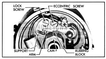
1950 Buick Contact Point Adjustment
NOTE: Since point opening decreases as rubbing block wears, always set new points as close to the high limit as possible.
Checking and Adjusting Contact Points with Feeler Gauge
A feeler gauge may be used to check contact point opening only when contact points are new. The opening of used or worn contact points cannot be measured accurately with a feeler gauge because of the irregular shape of contact surfaces. The gauge measures between high spots on the points instead of measuring the true point opening. See figure 10-65.
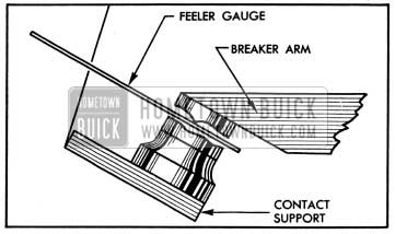
1950 Buick Incorrect Point Opening Obtained with Feeler Gauge
Use a clean, flat feeler gauge .015″ thick. With rubbing block on highest point of cam lobe adjust point opening (fig. 10-64) until feeler gauge goes between contact points with a very light drag. Use care to hold gauge exactly in line with opening to get an accurate measurement.
Checking and Adjusting Contact Points with Cam Angle Meter
Cam angle meters have come into general use for checking and adjusting contact point opening with engine running, or with the distributor being turned under operating conditions. These instruments measure the cam angle; sometimes called dwell angle, which is the number of degrees that distributor cam rotates from the instant that the contact points close to the instant when they open again. The cam angle increases as the point opening is decreased and is reduced as the point opening is increased.
Theoretically, a given cam angle should indicate a definite contact point opening. Experiments have proven, however, that the relationship between cam angle and contact point opening does not remain constant under all conditions. Misalignment of breaker arm rubbing block with the distributor cam, wear of rubbing block, slight variations in thickness of rubbing block, cam wear, etc., will often cause considerable variation in contact point opening for a given cam angle. In some cases, contact points adjusted to the given cam angle will have the expected point opening, while in others the point opening may be much less than the minimum required for good ignition.
For the reasons given, it is not possible to specify a cam angle setting which will insure correct contact point opening under all conditions. No cam angle setting is given in this manual since checking and adjusting contact point opening by means of dwell angle measurement is not recommended.
If a dwell meter is used, however, carefully follow the instructions of the instrument manufacturer. After checking or adjusting points by this method always make a final check to make certain that contact points are opening within the limits of .0125″ to .0175″. In cases where a chosen cam angle setting gives a point opening below the minimum tolerance, the point opening specification must be given preference.
10-46 REPLACEMENT OF 1950 BUICK DISTRIBUTOR CONTACT POINTS OR CONDENSER
When either the contact points or the condenser are to be replaced, these parts must be removed and installed as an assembly as described below, because the breaker arm spring tension must be adjusted to specified limits whenever the breaker arm spring and condenser lead attaching screw is loosened for any reason. Breaker arm spring tension cannot be adjusted with contact points and condenser installed in a distributor mounted on engine.
Breaker arm spring tension is very important. Weak tension will cause breaker arm to flutter and bounce at high speed resulting in engine missing. Excessive spring tension will cause rapid wear of breaker arm rubbing- block and cam, resulting in insufficient contact point opening. Excessive spring tension can cause tilting of the breaker base plate, which would affect contact point opening.
- Disconnect terminal connector lead from the terminal stud, detach condenser from breaker plate, remove contact support lock screw and remove contact points and condenser as an assembly.
- Disconnect condenser lead and breaker arm spring from contact support.
- Inspect contact points, terminal connector lead, and condenser lead. Test condenser (par. 10-50) if a reliable condenser tester is available. Discard unserviceable parts.
- Attach condenser connector lead, breaker arm spring, lock, and terminal connector lead to insulating block on contact support by means of the screw and nut. The head of screw and condenser lead terminal must be on inner side of block toward contact points, and the breaker arm spring, lock, connector lead terminal and nut must be on the other side of block in the order shown in figure 10-66.
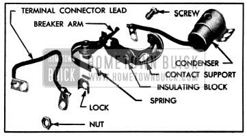
1950 Buick Position of Control Points and Other Parts for Assembly
Leave screw just loose enough so that the screw can be shifted in the slotted insulating block.
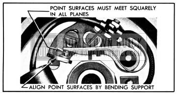
1950 Buick Contact Point Alignment
CAUTION: Do not bend the breaker arm as this may damage the rubbing block and loosen the pivot bushing in arm.
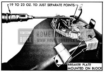
1950 Buick Checking Breaker Arm Spring Tension
10-47 1950 BUICK IGNITION TIMING
1950 Buick Ignition Timing Marks
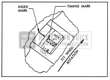
A 1950 Buick ignition timing mark is stamped on the flywheel and an index mark is stamped on the edge of the timing hole located in flywheel housing above the cranking motor. These marks may be seen when the timing hole cover is removed.
The timing mark stamped on flywheel is 1/8″ wide, knurled, and painted yellow. The 1/8″ width provides a tolerance of one degree when setting the timing. On Series 40-50, the timing mark is stamped “ADV 4°” and gives a timing setting 4° to 5° ahead of upper dead center. See figure 10-69. On Series 70, the timing mark is stamped “ADV 6°” and gives a timing setting 6° to 7° ahead of upper dead center.
1950 Buick Ignition Timing Marks-Series 40-50
The upper dead center mark on flywheel, stamped “U.D.C. 1-8”, follows closely behind the ignition timing mark as the flywheel rotates. See figure 10-69. This mark must not be used for 1950 Buick ignition timing.
1950 Buick Ignition Timing
Correct 1950 Buick ignition timing exists when the timing mark on flywheel is in line with the index mark on flywheel housing at instant that number one spark plug fires. It is desirable to have the index mark at the leading edge of timing mark; however, any position within the yellow band will give proper performance and economy.
1950 Buick ignition timing in advance of the specified setting may cause roughness in engine operation, even though high octane fuel is used. If detonation or “spark knock” is experienced with ignition timing set as specified refer to paragraph 3-5 (d) for information on fuel requirements.
Setting Timing with Synchroscope
1950 Buick ignition timing should be checked with a synchroscope or power timing light because this shows the actual timing with engine running. NOTE: Contact point opening must be within specified limits before setting ignition timing (par. 10-45).
- Remove timing hole cover. Connect synchroscope or power timing light to No. 1 spark plug wire at the plug or the distributor cap, in accordance with instructions of instrument manufacturer.
- Start engine and set it to idle at a speed not to exceed 350 RPM so that centrifugal and vacuum advance mechanisms are not in operation. This is absolutely necessary to insure correct timing.
- Direct the beam of timing light into the timing hole so that the timing mark on flywheel and index mark on flywheel housing can be observed. See figure 10-69. The index mark must fall within the yellow band of the ignition timing mark for proper timing.
- If necessary, loosen attaching bolts and turn the distributor housing very slowly in direction required to make the index mark fall within the yellow band of the ignition timing mark and as near leading edge of band as possible. Tighten distributor attaching screws and recheck timing.
- Reset engine idle to 450 RPM. Install spark plug cover and timing hole cover.
10-48 1950 BUICK SPARK PLUG CLEANING AND ADJUSTMENT
Removal and Inspection
- Use a 13/16″ socket wrench to remove all spark plugs. An oversized or worn wrench . may distort the spark plug shell and crack the insulator. If socket wrench is allowed to press against the outer end of plug, the insulator will be cracked or broken. See figure 10-70.
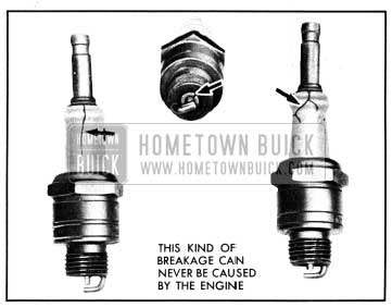
1950 Buick Broken Spark Plug Insulators
1950 Buick Spark Plug Cleaning
Spark plugs which have carbon or oxide deposits should be cleaned in a blast type spark plug cleaner. Scraping with a pointed tool will not properly remove the deposits and may damage the insulator. The following procedure covers use of the AC spark plug cleaner; however, the same principles apply to the use of any blast type cleaner.
- If spark plugs have a wet or oily deposit dip them in a degreasing solvent and then dry thoroughly with dry compressed air. Oily plugs will cause the cleaning compound to pack in the shell.
- Make sure that cleaner nozzle is not worn excessively; otherwise, the cleaning compound will not be properly directed into the shell.
- Place spark plug in adapter of proper size and hold adapter and plug in spark plug cleaner with one hand. Push cleaner hood half way down to “air-blast” position to blow out loose dirt and dry out plug, then press hood all the way down to “cleaning-blast” position and hold for 2 or 3 seconds. See figure 10-71.
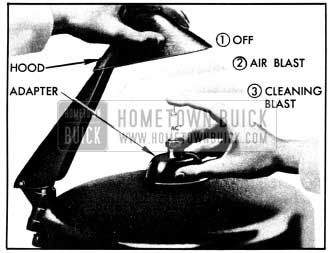
1950 Buick Use of AC Spark Plug Cleaner
Adjusting 1950 Buick Spark Plug Gap
Use round wire feeler gauges 0.023″ and 0.028″ in diameter to check the gap between spark plug electrodes. Flat feeler gauges will not give a correct measurement if the electrodes are worn. See figure 10-72.
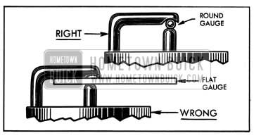
1950 Buick Right and Wrong Spark Plug Gauges
Adjust gap to 0.023″ “GO” and 0.028″ “NO GO” by bending the side electrode only; bending the center electrode will crack the insulator.
Setting spark plug gap to any other specification to improve idle or effect other changes in engine performance is not recommended.
Installation of 1950 Buick Spark Plugs
When installing spark plugs make sure that gaskets are in good condition to insure a tight seal and that surfaces on plug shells and seats in cylinder head are clean. AC type 46-X spark plugs are used in all series.
Screw plugs down by hand into firm contact with gaskets, then tighten them to 22-28 ft. lbs. torque, using a 13/16″ socket, an extension, and a torque wrench. If a torque wrench is not used, do not tighten plugs excessively.
Before connecting 1950 Buick ignition cables, make sure that terminal nuts on spark plugs are 3/4″ long and terminals on ignition cables are 13/16″ long. Any other nut and terminal combination may cause missing under certain operating conditions, due to the spark jumping from terminal to cover, or from terminal to block. This condition will not necessarily show up with engine idling. Push cable terminals all the way down on terminal nuts. CAUTION: Do not tighten the spark plug cover nuts enough to collapse the cover as this will cause insufficient clearance between spark plug wire terminal and cover.
10-49 1950 BUICK IGNITION COIL TESTS
Weak Coils
Most 1950 Buick ignition coils that are replaced by service stations are classified by them as weak. Many coils rejected as weak actually test up to specifications and give normal performance.
A coil that actually is weak will first affect engine performance when the ignition reserve is at a minimum. This may be in starting, low speed acceleration or top speed. Eventually the engine will fail to start.
High resistance connections in either the primary or secondary circuit wiring will react the same as a weak coil. Wide spark plug gaps, which require higher voltage than the coil can produce, put the coil under suspicion. High compression and lean carburetors increase the voltage requirements and lead to many needless coil changes. Leakage of high tension current through moisture on an unprotected coil terminal may produce carbon tracks which weaken the coil output voltage. For this reason the nipple on coil high tension terminal must be properly installed and in good condition.
When an ignition coil is suspected of being defective it should be tested as described below before being replaced.
Testing Coil for Open and Grounded Circuits
Before using a coil test instrument, the coil should be tested for open and grounded circuits, using a 110-volt test lamp and test points.
- Apply test points to both primary terminals of coil. If test lamp does not light, the primary circuit is open.
- Apply one test point to the high tension terminal, and the other test point to one of the primary terminals. If secondary circuit is not open, the lamp will not light but tiny sparks will appear at test points when they are rubbed over terminals. If secondary circuit is open, no sparks will occur.
- Apply one test point to a clean spot on the metal coil case and touch the other point to the primary and high tension terminals. If the lamp lights, or tiny sparks appear at the points of contact, the coil windings are grounded.
- A coil with open or grounded windings must be replaced since internal repairs cannot be made. It is unnecessary to test such a coil with instruments. If windings are not open or grounded, a test for short circuits and other internal defects should be made with a reliable coil test instrument.
1950 Buick Coil Test Instruments
Two general types of instruments are used in testing 1950 Buick ignition coils. One type makes use of an open or protected spark gap, while the other reports the condition of the coil on a meter.
The spark gap type of tester should always be used comparatively, that is, the questionable coil should be compared with a coil of same model that is known to be good. Both coils must be at the same temperature and identical test leads must be used. Certain variables caused by altitude, atmospheric or spark gap electrode conditions are usually present in the spark gap type of test.
The meter type testers are usually designed to permit testing the coil without making any connection to the secondary terminal. This eliminates the variables usually present in the spark type of test and avoids the necessity for comparison with a good coil.
Since different makes and models of coil testers differ in their methods of use, as well as in the markings on meters, the instructions of the manufacturer must be carefully followed when using any coil tester. The instrument must be frequently checked to make certain that it is accurately calibrated.
Regardless of instrument or method used, the coil must be tested at normal operating temperature because internal defects often fail to show up on a cold test.
10-50 1950 BUICK DISTRIBUTOR CONDENSER TESTS
When a condenser is suspected of being faulty it should be tested with a reliable condenser tester to determine whether it is actually the cause of 1950 Buick ignition trouble. The .condenser should be tested for (a) high series resistance (b) insufficient or excessive capacity (c) low insulation resistance.
A special condenser tester is required to make these tests. When using a condenser tester the instructions of the manufacturer must be carefully followed. IMPORTANT: The condenser must be at normal operating temperature when it is being tested.
High Series Resistance
High series resistance in the condenser circuit causes condenser to be slow in taking the charge and, consequently, a higher than normal voltage is developed across the contact points when they first start to open. This higher voltage causes more disturbance at the contact points, which in turn causes more rapid wear and more tendency toward oxidized surfaces. The condition can become severe enough to cause complete failure of the 1950 Buick ignition system. It would first show up during starting and low speed operation.
High series resistance may be caused by internal resistance in condenser or by resistance in the connections. Any defect caused by internal resistance should show up at low mileage since this does not change very much with time or use. The damaging changes are in the connections, in which looseness, corrosion, or broken strands may develop.
New condensers may have a series resistance as low as .05 ohm. Some condenser testers are set to reject condensers which have a resistance of .3 ohm; however, tests show that the resistance can go to .5 ohm before ignition performance is affected.
Insufficient or Excessive Capacity
The condenser specified for use in the 1950 Buick ignition system has a capacity of .18 to .23 microfarads.
If a condenser is used which does not have the specified capacity of .18 to .23 microfarads, excessive pitting of one contact point and a corresponding build-up of metal on the other contact point will result. A condenser having insufficient capacity will cause build-up of metal on the breaker arm (positive) point. See figure 10-73, view A. A condenser having excessive capacity will cause build-up of metal on the contact support (negative) point. See figure 10-73, view B.
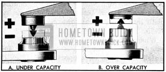
1950 Buick Result of Under or Over Capacity Condenser
In exceptional cases, pitting and metal buildup on contact points may be experienced even when condenser capacity is within the specified limits. In such cases the life of contact points will be improved by installing a condenser of high-limit capacity if metal build-up is on breaker arm point, or a condenser of low-limit capacity if metal build-up is on contact support point. There is usually sufficient variation in the capacities of stock condensers to permit selection of a high or low limit condenser by testing the available stock.
1950 Buick Low Insulation Resistance
A weak or leaking condenser is usually one that has absorbed water so that the insulation resistance of the winding is lowered to the extent that the condenser will not hold a charge satisfactorily. A condenser with low insulation resistance will drain sufficient energy from the 1950 Buick ignition system to lower the secondary voltage seriously. The condenser specified for use in the 1950 Buick ignition system is sealed to prevent absorption of water, and no other type should be used.
A leaky condenser usually does not affect engine performance except when hot. It is unlikely that a condenser with low insulation resistance would cause missing at low or medium speeds under conditions where the condenser does not get hot. A condenser that has low enough resistance to affect engine performance when cold would probably be indicated as broken down on most condenser testers.
Condenser testers equipped to check condensers for low insulation resistance usually give a reading in megohms, a megohm being one million ohms. The scale is marked to indicate whether the condenser is good or bad.
When testing a condenser for low insulation resistance the lead should always be disconnected from the distributor. See paragraph 10-46. Since the distributor terminals and the connected circuit have much lower insulation resistance than the condenser, failure to disconnect the condenser lead will give a reading much too low.
10-51 1950 BUICK DISTRIBUTOR OVERHAUL
Removal of 1950 Buick Distributor
- Disconnect primary wire from distributor and disconnect pipe from vacuum control unit. Remove distributor cap.
- Crank engine until distributor rotor is in position to fire No. 1 cylinder, and the timing mark on flywheel aligns with index on flywheel housing.
- Remove the two distributor retaining bolts and lift distributor out of crankcase.
Disassembly of 1950 Buick Distributor
- Remove rotor and breaker plate ground lead, then remove the vacuum control. See figure 10-74.
1950 Buick Distributor Parts
Cleaning and Inspection of 1950 Buick Distributor Parts
- Wash all parts except the condenser, leads, rotor, cap, and breaker plate assembly in clean kerosene or other solvent and dry thoroughly. Hold housing horizontal while washing interior to avoid getting cleaning solution into the shaft lubricant reservoir.
- Test the condenser if a reliable condenser tester is available (par. 10-50).
- Inspect ground and terminal connector leads for oil soaked or damaged insulation, broken strands, or loose terminals.
- Inspect cam for excessive wear of cam lobes.
- Inspect shaft for excessive looseness in bushings in distributor housing. Inspect distributor gear for wear or scoring of teeth. Check end play of shaft with feeler gauges; end play should not exceed .007″.
- Inspect contact points for excessive wear, pitting or burning. Inspect breaker arm spring for cracks and rubbing block for wear or looseness.
- Inspect breaker plate assembly for looseness which would permit tipping or rattling of the base plate. Normally it is unnecessary to disassemble this unit; however, if it is very dirty it may be disassembled for cleaning and inspection. Remove stop washer and shims from base plate post, remove :retainer washer from base plate hub and separate the parts. See figure 10-75.
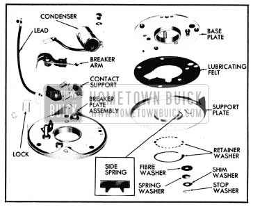
1950 Buick Breaker Plate Disassembled
When reassembling the breaker plate, saturate the felt washer with 10W engine oil, then install base plate on support plate. Place the small side spring in recess in support plate so that the two points will be between the ends of retainer washer when installed. This spring helps to prevent side play of base plate. In some assemblies two retainer washers are used, depending on production tolerances.. Place fibre, spring, shim and stop washers on base plate post in the order named. See figure 10-75.
- Whether breaker plate has been disassembled or not, attach a scale and check the pull required to move the base plate on the support plate. The pull should not exceed 16 ounces nor be less than 8 ounces. See figure 10-76.
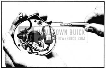
1950 Buick Checking Tension on Base Plate
If pull is less than 8 ounces add shim washers to base plate post between the stop and spring washers. If pull exceeds 16 ounces remove shim washers as required. This assembly tension is very important in preventing tipping of base plate and controlling the amount of friction opposing rotation of the base plate on the support plate.
- If contact points are to be replaced, assemble contact support, breaker arm and condenser, install on breaker plate, then align points and adjust breaker arm spring tension as described in paragraph 10-46, steps 4 through 8. Set contact support out to limit of lock screw hole. Attach condenser to breaker plate.
- Replace all distributor parts that are not in good condition. If the gear, shaft, or housing requires replacement, proceed with subparagraph d; otherwise proceed with subparagraph e.
Replacement of 1950 Buick Distributor Gear, Shaft, or Housing
- Remove flathead screw and spring from housing to relieve pressure on the felt plug which bears against distributor shaft.
- Grind or file off the peened-over head of gear pin and drive pin out.
- Remove gear, shim washer and thrust washer from shaft, then remove shaft and plate assembly and thrust washer from housing.
- When shaft and plate assembly is installed in housing place one thrust washer between weight plate and housing. A shaft shim washer of proper thickness must be placed between the lower thrust washer and gear to provide .002″ to .007″ end play in shaft when gear is installed. Shim washers are furnished in .005″ and .010″ thicknesses.
- Peen over the head of gear pin after installation of shaft is completed, then recheck end play.
Assembly of 1950 Buick Distributor
- Place advance weights over pins on shaft weight plate. Install cam over shaft with advance cam between the weights and with the stop pin in hole in weight plate. Install advance weight springs on pins. NOTE: One light and one heavy spring are used.
- Place plate over weights with ridged side down against weights. Install locks and nuts and bend tongue of locks up against nuts. See figure 10-77.
1950 Buick Installation of Advance Weights, Cam, Springs and Plate
- Rotation (top view) – Counterclockwise
- Contact Point Opening – 0125″ to .0175″
- Breaker Arm Spring Tension – 19 to 23 oz.
- Vacuum Advance-Distributor Degrees and Vacuum
- Start travel at 5″ to 7″ (Hg.) of Vacuum
- 5 to 6 Deg. at 10″ to 13″ (Hg.) of Vacuum
- Centrifugal Advance-Distributor Degrees and RPM
- 0-2 Deg. at 250 RPM*
- 5-7 Deg.at400 RPM*
- 11-13 Deg. at 1500 RPM*
*1/2 Engine RPM
Installation of 1950 Buick Distributor
NOTE: Before installation of either a new or repaired distributor apply a few drops of engine oil to drain hole near lower end of housing and apply chassis lubricant to fitting until lubricant emerges from relief hole in housing. Rotate shaft several times by hand to distribute lubricant and to make sure that shaft turns freely.
- Check to make sure that timing mark on flywheel is aligned with index mark on flywheel housing, with No. 1 piston on compression stroke.
- Place a new cork oil seal on distributor housing.
- Rotate distributor cam in direction of arrow on cam until rotor is nearly in position to fire No. 1 cylinder, and contact points have just closed from the preceding cam lobe which fires No. 4 cylinder. This position is necessary to allow for the amount that cam will rotate as the driving gears are meshed.
- Rotate oil pump shaft with screw driver to align slot in shaft with tongue on lower end of distributor shaft. Install distributor in crankcase with vacuum control pointing to rear of engine and approximately parallel to side of crankcase. See figure 10-78.

1950 Buick Position of Distributor for Installation
10-52 1950 BUICK IGNITION SWITCH AND LOCK REPAIRS
1950 Buick Ignition Switch Key
If 1950 Buick ignition key sticks or feels rough as it is inserted into the lock, examine it for burrs and smooth up with a fine cut file. Blow finely powdered graphite into lock cylinder, then work key in and out of cylinder a number of times to work graphite into tumblers. Do not use oil in lock cylinder as this will cause tumblers to stick.
If 1950 Buick ignition switch key is lost and key code number is not known, the code number will be found stamped on the door safety lock, which must be removed. A new key can be cut by using this code number.
1950 Buick Lock Cylinder Replacement
To remove lock cylinder, insert key and turn ignition switch to “OFF” position. Insert a stiff wire (paper clip) in small hole in face of cylinder (fig. 10-79, view A) to depress the pin which locks the cylinder, turn cylinder clockwise and pull out.
1950 Buick Removing Lock Cylinder having a Loose Cage Bar
To install lock cylinder insert key, place cylinder in switch slightly clockwise from “OFF” position, press inward and turn cylinder counterclockwise.
1950 Buick Ignition Switch Replacement
- Disconnect ground cable from battery to avoid a possible short circuit when disconnecting wires from switch terminals.
- Remove lock cylinder (subpar. b, above).
- Remove shield which is attached to flange of instrument panel by two “theft-proof” screws; these must be removed with pliers since they cannot be removed with a screwdriver.
- Disconnect wires from switch terminals, remove switch attaching screws and remove switch from forward side of instrument panel.
- When switch is installed be careful to connect wires to terminals as shown in the chassis wiring circuit diagrams in Section 10-J. Be sure to install switch terminal shield with new “theft-proof” screws. Connect battery ground cable in proper manner to make an initial winding of clock and set clock. See Paragraph 10-66.
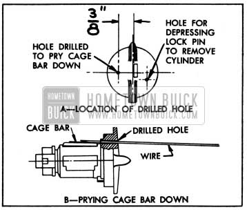
Removal of 1950 Buick Lock Cylinder Which Cannot be Unlocked with Key
When 1950 Buick ignition switch fails to unlock with the proper key, and lock has previously been operating satisfactorily, the lock cylinder can be removed as follows:
- Draw a centerline on cylinder at 90° to key slot, insert key, and make a prick punch mark on centerline 3/8″ from side of key. See figure 10-79, view A. Carefully drill a .0465 hole (No. 56 drill) through cylinder flange at this point.
- File the end of a stiff wire (paper clip) to a taper. Insert this end of wire in drilled hole to pry the cage bar assembly down so that lock cylinder can be turned. See figure 10-79, view B. After turning cylinder slightly, remove the wire to avoid wedging, then remove lock cylinder in the regular manner (subpar. b, above).
- Stake cage bar in place as shown in figure 10-80.
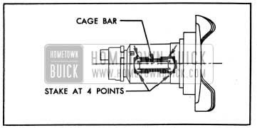
1950 Buick Cage Bar Staked In Place
Staking must not distort cage. Reinstall lock cylinder and check operation with key. If operation is satisfactory, plug the drilled hole with a small pin No. 00 x 1/8″ (Parker Kalon type “U”).
Leave A Comment
You must be logged in to post a comment.