SECTION 6-A 1950 BUICK CHASSIS SUSPENSION SPECIFICATIONS, DESCRIPTION, SERVICE RECOMMENDATIONS
6-1 1950 BUICK CHASSIS SUSPENSION SPECIFICATIONS
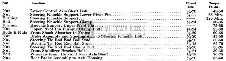
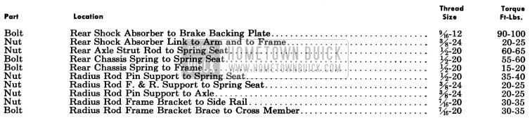
1950 Buick Chassis Suspension Tightening Specifications
Use a reliable torque wrench to tighten the parts listed, to insure proper tightness without straining or distorting parts. These specifications are for clean and lightly lubricated threads only; dry or dirty threads produce increased friction which prevents accurate measurement of tightness.
1950 Buick Chassis Tightening Specifications
1950 Buick Chassis Tightening Specification
1950 Buick Chassis Springs

1950 Buick Chassis Springs Specifications
1950 Buick Shock Absorbers
1950 Buick Shock Absorbers Specifications
1950 Buick Wheels and Tires
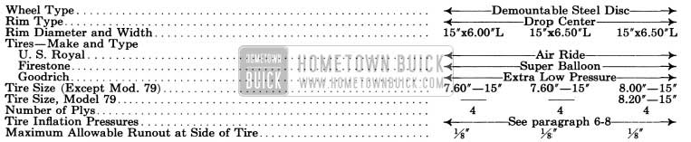
1950 Buick Wheels and Tires
Dimensional Specifications
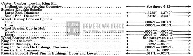
1950 Buick Chassis Dimensional Specifications
NOTE: Dimensions and limits given in these specifications apply to new parts only. Where limits are given, “T” means tight and “L” means loose.
6-2 1950 BUICK FRONT WHEEL SUSPENSION
The 1950 Buick front wheel suspension allows each front wheel to rise and fall, due to change in road surface level, without appreciably affecting the opposite wheel.
Each wheel is independently connected to the frame front cross member by a steering knuckle steering knuckle support, lower control a assembly, and an upper control arm on the shock absorber. See figure 6-1.
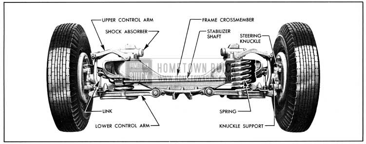
1950 Buick Front Wheel Suspension
The upper and lower control arms are so placed and proportioned in length that they allow each knuckle support, spindle, and wheel to move through a vertical plane only. The front wheels are held in proper relation to each other for steering by means of two tie rods which connect to steering arms on the steering knuckles and to the pitman arm on the steering gear.
A coil type chassis spring is mounted between the frame front cross member and a spring seat in each lower control arm assembly. A large rubber bumper is mounted on the outer end of each lower control arm to limit travel of the arm during compression of chassis spring.
A similar rubber bumper is mounted on the frame under each upper control arm to limit travel of arm during rebound of chassis spring.
Side roll of the front end of chassis is controlled by a spring steel stabilizer shaft. The shaft is mounted in rubber bushings supported in brackets attached to lower flange of each frame side rail. The ends of stabilizer shaft are connected to the front sides of lower control arms by links which have rubber grommets at both ends to provide flexibility at the connections and prevent rattle. See figures 6-1 and 6-15.
The lower control arm assembly consists of two drop forged steel arms solidly riveted to a stamped steel spring seat to form a rigid V-shaped unit. A small plate riveted above the spring seat serves as a mounting for a rubber bumper and a point of connection for the stabilizer link. Hardened steel threaded bushings are screwed solidly into the inner ends of the forged arms to provide thread-type bearings on the ends of the control arm shaft which is attached to the frame front cross member. A large threaded pivot pin held by a lock washer and nut connects the steering knuckle support to the lower control arm. See figure 6-2.
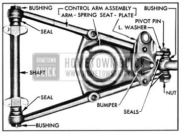
1950 Buick Lower Control Arm and Shaft Assembly
A large threaded hardened steel bushing is screwed solidly into the lower end of each steering knuckle support to provide a thread-type bearing on the pivot pin in outer end of lower control arm. The upper end of knuckle support provides for a threaded, clamp type pivot pin which connects upper end of support to outer end of the upper control arm. The threaded ends of the upper pivot pin seat in internally threaded hardened steel bushings mounted in outer end of upper control arm. See figure 6-3.
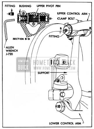
1950 Buick Steering Knuckle Support and Pivot Pins
The eccentric type steering knuckle support upper pivot pins provide adjustment for both caster and camber. The threaded pin and bushings permit adjustment of caster by turning the pin, which moves the upper end of knuckle support fore or aft, depending on rotation. The large diameter threaded middle section of pin is eccentric to the ends so that camber is also changed by turning the pin. A hex recess is broached in one end of pin for insertion of the adjusting wrench after removal of the lubrication fitting from the clamped type pivot pin bushing. See figure 6-3.
Rubber seals are installed on lower control arm shafts and on lower and upper pivot pins to exclude dirt and water from the threaded bearing surfaces. Lubrication fittings are provided at all bearing locations.
The steering knuckle is attached to knuckle support by a hardened steel king pin which is locked in knuckle support by a tapered pin. Bronze bushings in steering knuckle provide bearings for king pin. Vertical thrust is taken by a ball bearing between the steering knuckle and knuckle support. The steering knuckle spindle supports the wheel hub with two New Departure adjustable cup and cone ball bearings. The outer end of hub is closed by a cap and inner end is sealed with a packing to exclude dirt and water from bearings. See figure 6-4.
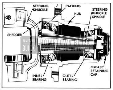
1950 Buick Steering Knuckle, Wheel Bearings and Hub
6-3 1950 BUICK REAR WHEEL SUSPENSION
1950 Buick rear wheels are not independently sprung since they are mounted on axle shafts incorporated in the rear axle assembly. The rear wheels are held in proper alignment with each other by the rigid construction of the rear axle housing. They are held in alignment with the rest of the chassis by the torque tube and radius rod between car frame and the rear axle assembly.
Two coil type chassis springs are mounted between the frame cross member at top of kick up, and spring seats welded to the axle housing near each end. Ride control is provided by a double-acting hydraulic shock absorber mounted on each rear brake backing plate and connected to the frame by a rubber bushed steel link. Side sway of the chassis springs and rear end of frame is prevented by the transverse radius rod. Large rubber bumper and rubber rear axle stops are bolted to lower flange of frame side rails over axle housing to limit travel of axle housing during compression of the chassis springs. See figure 6-5.

1950 Buick Rear Wheel Suspension
6-4 1950 BUICK CHASSIS SPRINGS
The 1950 Buick front chassis springs have a small coil at the top end only, which fits around a center cup attached to the frame by one shock absorber bolt. A rubberized fabric insulator is located between upper end of spring and the frame.
The 1950 Buick rear chassis springs have small coils at both ends. The upper end of each spring is attached to the frame by a bolt and clamp. A rubberized fabric insulator is located between upper end of spring and the frame. Another insulator is located between the spring clamp and the flat washer on attaching bolt. The lower end of each rear spring is attached to a spring seat on rear axle housing by a spring clamp and bolt.
Special rear chassis springs are available in overload capacities for use under abnormal conditions. It is not recommended that any series rear axle be overloaded in excess of 500 pounds. Use of overload rear chassis springs is explained in paragraph 6-21.
All 1950 Buick front chassis springs are identical in appearance, and rear springs also, Chassis springs are of different load capacities for different models; therefore springs may not be interchangeable between models. Each spring has the part number stamped on one end coil for identification. The correct spring to use for each model is specified in the Master Parts List.
6-5 1950 BUICK FRONT SHOCK ABSORBERS
Delco double acting, opposed piston type hydraulic shock absorbers are used on all models. Front shock absorbers are mounted on top of frame front cross member. Two of the three attaching bolts fit in reamed holes to insure correct alignment of shock absorber with other front suspension members. The arms which are welded to outer ends of shock absorber camshaft form the upper control arms of the front wheel suspension system.
Right and left shock absorbers are identical and interchangeable, however, calibrations may differ between car models. Shock absorber calibrations for each model are given under Specifications (par. 6-1) and are also given in the Master Parts List. The manufacturer’s model number, coded date of manufacture, and the calibration code numbers are stamped on one end cap of each shock absorber.
The 1950 Buick shock absorber body contains a fluid reservoir connected to two cylinders in which rebound and compression pistons operate. Both pistons are fastened together and are simultaneously actuated by a cam located between their inner ends. The cam is mounted on a shaft which extends through both sides of the body and is rotated by the upper control arms serrated to the outer ends. The rebound piston and cylinder are toward the upper arm. See figure 6-6.
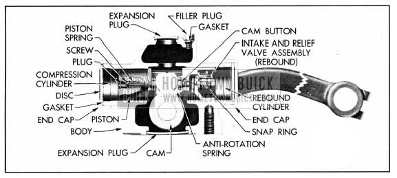
1950 Buick Front Shock Absorber-Sectional View
Each piston is fitted with a spring loaded valve which operates as a main control valve and also as an inlet valve for return of fluid to outer end of the cylinder. The rebound and compression valves have different calibrations, which govern the rate at which fluid passes through them. The calibration code number is stamped on each valve for proper identification.
Each compression and rebound valve has a bleeder hole in the valve stem. Under normal car operation, when the fluid pressure is applied by the piston, transfer of fluid takes place through the bleeder hole, but for violent road shocks the valve opens against spring pressure, allowing a more rapid transfer of fluid past the valve seat as well as the bleed hole.
As the shock absorber arm moves downward, due to car Spring rebound movement, pressure set up in the rebound cylinder forces fluid through the bleeder hole or opens the rebound valve by compressing the valve spring; at the same time, the compression valve moves off its seat in the body, due to the partial vacuum created in the compression cylinder, and the compression cylinder is filled with fluid. As the shock absorber arm moves up, pressure set up in the compression cylinder forces fluid through the bleeder hole or opens the compression valve by compressing the valve spring; at the same time, the rebound valve moves off its seat in the body, due to the partial vacuum created in the rebound cylinder, and the rebound cylinder
is filled with fluid. Thus, the action of the fluid is the same in both the rebound and compression cylinders, but the rate of movement of the arm up and down is controlled by the size of the bleeder hole and weight of the spring of the rebound and compression valves.
6-6 1950 BUICK REAR SHOCK ABSORBERS
Delco double acting, parallel cylinder type hydraulic shock absorbers are used on all models. Rear shock absorbers are mounted on the brake backing plates and the arms are connected to the frame by non-adjustable rubber bushed steel links. Right and left rear shock absorbers are identical in design but are not interchangeable. Calibrations for each car model are given under Specifications (par. 6-1) and are also given in the Master Parts List. Calibration code numbers are stamped on the valve nuts of each shock absorber.
The 1950 Buick shock absorber body contains a fluid reservoir above two parallel cylinders in which compression and rebound pistons operate. Either piston is moved downward by a cam located to bear against the upper end of the piston; while one piston is being moved downward by the cam, the other is moved upward by a heavy coil cap spring. The cam is mounted on a shaft which extends through one side of the body and is rotated by the shock absorber arm attached to the outer end. The compression piston and cylinder are toward the shock absorber arm. See figure 6-7.
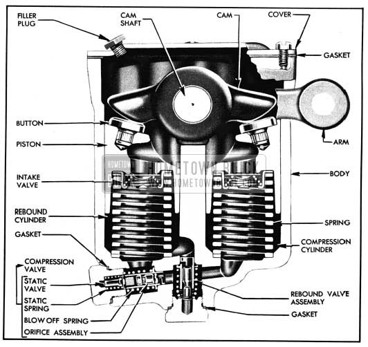
1950 Buick Rear Shock Absorber-Sectional View
While the action of the rear shock absorbers is similar to the front shock absorbers (par. 6-5), they are much faster acting due to the drilled passage from one cylinder to the other. Their construction differs from the front shock absorbers as follows:
- The oil discharge is from one cylinder to the other by means of drilled passages in the shock absorber body.
- The compression and rebound valves are located in the ends of the drilled passages rather than in the pistons. The compression and rebound valves act as main control valves only.
- An intake valve is provided in each piston of the rear shock absorber and its only function is to replenish fluid lost by piston leakage as the cylinders are filled under pressure from valve discharge of opposite cylinder.
6-7 1950 BUICK WHEELS AND TIRES
1950 Buick Wheels
Wheels are demountable disc type with the rim welded to wheel disc to form a unit assembly. The wheels have wide drop center type rims designed to give ample support for the tire sizes used as standard equipment. The rims have tapered tire bead seats which cause tire beads to wedge tightly in place when tires are inflated.
1950 Buick Tires and Tubes
Tires on all models are low pressure balloon type, made of a combination of synthetic and natural rubber. Tubes are made of synthetic rubber, which has the advantage of holding air pressure somewhat better than natural rubber. Standard production tire sizes are given in paragraph 6-1 (d).
All tires and tubes used as standard factory equipment have been worked out with the tire manufacturer for stability. This does not imply that other makes and types of tire and tubes are not suitable for Buick cars, but owing to the large number of tire and tube makes and designs it is impossible for ride and handling calibrations to be worked out for each one.
Tires other than those used as standard equipment may cause a wander. Larger tires will reduce clearance at fenders and be difficult to mount in spare carriers. Tires with more plys may cause hard riding. Some types of “puncture proof” tubes are difficult to balance and may cause “tramp.”
6-8 SERVICE RECOMMENDATIONS CHASSIS SUSPENSION
Barring accident or rough handling that affects wheel alignment, the chassis suspension requires no attention other than the items specified under Lubricare Instructions (par. 1-1). The following additional services pertaining to tires will insure maximum tire life and bring to attention any out of line condition affecting the tires.
1950 Buick Tire Inflation
Maintenance of correct inflation pressure in all tires is one of the most important elements of tire care. Correct tire pressure is also of great importance to ease of handling and riding comfort. Overinflation is detrimental to tire life but not so much as underinflation.
Inflate all tires according to tire temperature as follows:
- 24 lbs. Starting Pressure-after car has been standing for 3 hours or driven less than one mile. In temperatures below freezing, inflate tires 2 lbs. higher.
- 26 lbs. City Pressure-after car has been driven 3 miles or more BELOW 40 MPH.
- 28 lbs. Highway Pressure-after car has been driven 3 miles or more ABOVE 40 MPH.
WARNING: It is impossible to inflate tires correctly when HOT. Pressure normally increases as tires heat up while driving. Do not deflate tires to offset this increase in pressure.
Driving without tube valve caps contributes to underinflated tires. The valve cap keeps dirt and water out of the valve core and seals the valve against leakage. Whenever tires are inflated be sure to install valve caps on all tubes and tighten firmly by hand. Make sure that rubber washer in cap is not damaged or missing.
If tires are checked at frequent intervals and adjusted to correct inflation pressure, it is often possible to detect punctures and make a correction before a tire goes flat, which may severely damage tire and tube if car is in motion. This is because tubes usually do not go flat for days and even weeks after they are punctured. Slight differences in pressure between tires will always be found, but a tire that is found to be 3 or more pounds below the lowest of its running mates can be suspected of having either a leaking valve or a puncture.
Tire Inspection
All tires should be inspected regularly to avoid abnormal deterioration from preventable causes. If tires show abnormal or uneven wear the cause should be determined and correction should be made.
See that no metal or other foreign material is imbedded in the tread. Any such material should be removed to prevent damage to tread and tire carcass.
Cuts in a tire which are deep enough to expose the cords will allow dirt and moisture to work into the carcass and ruin the tire unless promptly repaired. Attention to cuts and cracks in tires containing synthetic rubber is particularly important because cuts spread more rapidly in synthetic than in natural rubber. Shallow cracks or cuts may be arrested by grooving but deep cracks or cuts should be repaired promptly.
Tires which are worn smooth are more likely to skid on wet surfaces than tires with a normal anti-skid design. Water is a lubricant to rubber and there are no sharp edges and gutters in a smooth tire to scrape the water off and allow the tire to make a dry path in which to run. In addition, smooth tires naturally are not as thick as new tires and therefore puncture more easily. It is good practice to replace smooth tires with new tires as insurance against tire accidents.
Interchanging Tires
Tires tend to wear unevenly and become unbalanced as mileage accumulates. Uneven tire wear is frequently the cause of tire noises which are attributed to rear axle gears, bearings, etc., and work is sometimes needlessly done on rear axles in an endeavor to correct the noise.
Tire life will be increased and uneven wear and noise will be less likely to occur if the tires, including the spare, are balanced and interchanged at regular intervals of approximately 5000 miles. The recommended method of interchanging tires is shown in figure 6-8.
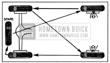
1950 Buick Method of Interchanging Tires
Use of Tire Chains
Do not use tire chains on the front wheels under any circumstances because they will interfere with the steering mechanism. Any of the conventional full-type non-skid tire chains can be used on the rear wheels.
Tire chains should be loose enough to “creep” but tight enough to avoid striking fenders or other parts. If chains remain in one position the tire side wall will be damaged. Tension springs (either metal coil springs or the rubber band type) must also be used in order to prevent chains contacting frame, etc. The use of tension springs will also reduce ordinary chain noise caused by loose cross links contacting pavement, and prevent damage to rear wheel shields.
Leave A Comment
You must be logged in to post a comment.