SECTION 13-D 1950 BUICK INTERIOR TRIM AND SEATS
13-18 1950 BUICK DOOR TRIM PAD REMOVAL AND INSTALLATION
- Remove all door inside handles by pushing inward on the escutcheon and removing the handle retaining spring, using Door Handle Pliers KMO 601. A slight rotating motion of the pliers will easily remove the retaining spring. See figure 13-37.
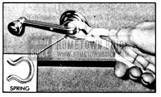
1950 Buick Removing Handle Retaining Spring with Pliers KMO 601
- Remove garnish molding attaching screws, then grasp upper horizontal portion of molding and pull away from door with a downward motion to release it. Remove the rubber grommets which slip over lower ends of molding.
- Remove inside safety locking rod knob, remove retaining screws at both ends of belt finishing molding, then lift molding up to free it from retaining clips.
- Remove arm rest and remove screws and finish washers at lower corner of trim pad.
- Pry front and rear edges of trim pad loose from door inner panel, using a suitable flat tool, then lift pad to disengage it from hooks at center of door and the retainer at bottom edge. NOTE: Trim pad can be pried loose more easily and with less danger of breaking off nails if pad is first lightly tapped along both edges with a mallet to relieve the binding effect of the nails.
- Install trim pad and related parts by reversing procedure for removal, observing the following points:
- Nails that are loose or damaged so they will not hold properly should be removed from trim pad. Attach trim pad nailing tabs, Group 10.357, Part No 4081772, to metal nailing strip where nails are missing.
- When trim pad is being placed on door, bow it slightly so that the hooks on door inner panel can be engaged in slots in trim pad foundation.
- Be sure to hook the metal retainer on lower edge of trim pad over the retainer on door inner panel. See figure 13-38.
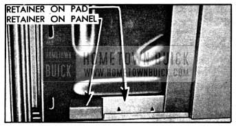
1950 Buick Retainers at Lower Edge of Trim Pad
- Before door inside handles are installed, place retaining spring in slots, using new springs if old springs are weak or distorted.
Locate each handle on shaft at the same angle as the corresponding handle on opposite door, with windows and ventilators closed, and tap handle with rubber mallet to engage retaining spring in groove in shaft.
13-19 1950 BUICK HEADLINING REMOVAL AND INSTALLATION
NOTE: Clean hands and tools are essential when working on the headlining.
Removal of 1950 Buick Headlining
- Remove radio antenna control knob and escutcheon plate, also both sunshade assemblies.
- Remove dome lamp assembly. Where installed over the headlining also remove dome lamp switch.
- Remove windshield, rear quarter, and back window garnish moldings.
- Remove rear seat cushion and seat back (par. 13-21) and the seat back trim valance when installed.
- Remove back compartment top trim panel by loosening cemented front flap, unbending tabs under flap, then freeing remainder of panel from cement.
- Remove tacks from headlining at windshield, rear quarter, and back window openings, also at rear compartment shelf. Use care to avoid damaging headlining where it is cemented in place. NOTE: When removing tacks use a thin blade screw driver or similar tool placed under the headlining. If placed under tack head, the headlining may be damaged.
- Carefully release headlining from the headlining retainer tabs at the upper corners of the windshield opening. Also release headlining from the retaining tabs at rear quarter section.
- Starting at the front corners, disengage the headlining from its retainers along both side roof rails. By loosening retainer screws along both side roof rails progressively as headlining is loosened, it is easier to disengage the headlining from the retainer. See figure 13-39.
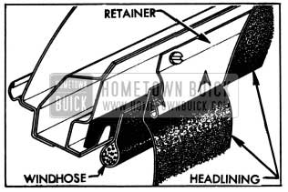
1950 Buick Headlining Retainer on Roof Rail
- Remove screw and silencer holding end of each headlining support wire to right roof rail, then starting at the front disconnect headlining support wires from left roof rail. Left end of each support wire has an offset over which a rubber thimble is placed where it enters hole in roof rail. At the roof bow bend down the metal clips to release headlining listing wire then proceed to rear in removal of headlining.
Installation of 1950 Buick Headlining
The 1950 Buick headlining support wires vary in length according to width of body where each is used. If these are removed from listings for any reason, be sure that each is re-installed in the listing from which it was taken, or is installed in the corresponding listing if a new headlining is being installed.
- Hang headlining at the single roof bow and bend up metal clips to retain the listing wire. If a clip is broken off it can be attached with a metal tapping screw. Make sure that headlining is properly centered and that dome lamp opening is lined up evenly in relation to dome lamp support.
- Attach left ends of support wires (with rubber thimbles) to left roof rail and attach right ends of support wires to right roof rail with silencers and screws.
- Tack or staple headlining around back window and at rear seat back compartment shelf. On the 4-door style, secure headlining material to retainer tabs at wheelhouse area.
- Stretch headlining to the front and tack or staple at windshield opening. All fullness must be removed from front to rear before installing the sides of headlining.
- Engage headlining to retainer tabs at upper corner of windshield.
- Tighten retainers to roof side rails then carefully tuck the edges of headlining up between the retainers and the windhose, using Headlining Inserter J 2772. See figures 13-39 and 13-40.
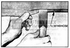
1950 Buick Tucking Headlining Behind Retainer with Inserter J 2772
- Tack or staple headlining above rear quarter windows on the 2-door style.
- Reinstall all the remaining parts by reversing procedure for removal.
- Use a soft brush to remove any lint from headlining and brush headlining in even strokes from rear to front. If air hose is used there is danger of matting and streaking the nap of headlining. Refer to paragraph 13-2 (d) if headlining requires further cleaning.
13-20 1950 BUICK FRONT SEAT SERVICE OPERATIONS
The 1950 Buick front seat cushion is built into the seat cushion frame assembly and cannot be removed except by removing the entire seat assembly. The front seat back assembly, either full width or split type, may be removed from the seat cushion and frame assembly without removing the entire seat assembly from body.
1950 Buick front seat cushions and seat backs are built upon separate zig-zag type spring assemblies which are attached to the metal frame assemblies. The zig-zag spring assemblies are shown in figure 13-41.
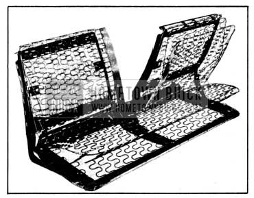
1950 Buick Seat and Seat Back Spring Assemblies-Split Type
Removal and Installation of 1950 Buick Seat Side and Back Trim Panels
- Loosen set screw and remove seat adjuster control handle from left side of seat. This operation not required for removal of right side panels only.
- Remove screws at each curved end of seat side trim panel, disengage the retaining tab on inner surface of panel and lift the panel assembly out of position. The extension at rear inner end is a separate part which comes off with the panel assembly.
- Remove outer screw from each robe cord escutcheon and remove cord. Remove inner screw and remove escutcheon. The escutcheon screws attach the back trim panel to seat back frame.
- On full width back, remove trim panel retaining screw at each lower corner. On split type back, remove retaining screws along lower edge of trim panel. Lift back trim panel out of position.
- Install panels by reversing procedure removal.
Removal and Installation of 1950 Buick Front Seat and Seat Adjuster
- Remove 1950 Buick seat side panels (subpar. a, above).
- Remove bolts attaching the four seat adjuster supports to body floor pan. See figure 13-42.
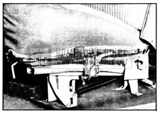
1950 Buick Front Seat Adjuster
- Remove the front seat assembly from body with seat adjuster unit attached.
- Remove seat adjuster assembly from seat as follows: Detach the locking rod from the locking rod clip on the center bar of the seat frame. The seat front and rear attaching bolts are installed in an inverted position through the top of the upper channel. To remove the front bolt, push the adjuster to the rear and remove exposed bolt. To remove rear bolt, push adjuster forward and remove bolt. Remove center attaching bolt and remove seat adjuster assembly.
- Install seat adjuster and seat assembly by reversing procedure for removal. The slotted bolt holes in seat adjuster supports permit lateral adjustment for alignment of adjuster units on each side of body.
Removal and Installation of Front Seat Back-Full Width Type
- Remove seat side and back trim panels (subpar. a, above).
- Remove four bolts retaining the legs of the seat back frame to seat cushion frame at each lower rear side.
- Lift seat back assembly upward so that legs of seat back disengage from channel sections on seat cushion frame.
- To install, reverse this procedure.
Removal and Installation of Front Seat Back-Split Type
- Remove seat side trim panel (subpar. a, above).
- At the bottom center of the curved center hinge arms, remove the cotter pin and disengage the hinge pin anchoring both left and right seat backs to the center of the cushion frame.
- At the bottom of the outer curved hinge arms of the seat back, remove the spring retaining clip from end of hinge pin. (Hinge pin is stationary at this point and cannot be removed.)
- To remove, lift up seat back at center and move it sidewise to disengage outer hinge arm from the stationary hinge pin.
- To install, reverse this procedure.
Removal and Installation of Front Seat Cushion Trim
- Remove entire front seat assembly from body (subpar. b, above), remove seat back (subpar. c or d, above) and place seat cushion and frame assembly upside down on a clean bench.
- Referring to figure 13-43, remove hog rings holding bottom rear facing indicated at (1) to spring and frame. Remove loose wadding (2) from back of seat frame.
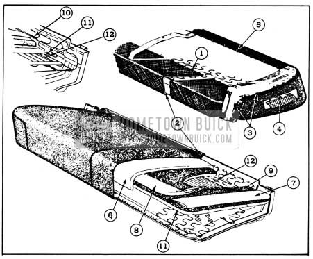
1950 Buick Front Seat Cushion Trim Installation
- Remove hog rings securing end facing to slots in seat frame at (3). Also remove hog rings holding end listing to spring at (4).
- Remove hog rings retaining front facing at (5) to slots at rear of front frame bar.
- Turn cushion over, turn back trim cover and remove cotton pad (6), cotton batts (7) and (8) and latexed hair pad (9).
- Remove hog rings securing top rear facing to spring at (10).
- Remove hog rings holding cotton pad to springs at (11). If necessary, the wire insulator may be removed by disengaging hog rings as indicated at (12).
- Before installation of seat cushion trim make sure all listing wires are installed in the pockets in the skirt of seat cushion.
- Install insulator if removed, securing it at front, rear, and at each corner with hog rings.
- Attach cotton pad to spring at (11) with eight hog rings along each front and rear edge and three along each end. See figure 13-43.
- Hog ring the top rear facing to spring with thirteen rings as shown at (10).
- Place latexed hair pad over foundation pad at (9) and tuck snugly at rear.
- Place a cotton batt over hair pad at each end (7) and along front (8). Batt is opened one-third.
- Place cotton pad (6) over batts with tobacco cloth backing down against the latexed hair pad . Tuck snugly at rear.
- Turn cushion upside down and hog ring the front facing at (5) to slots at rear of front frame bar with fourteen hog rings.
- Secure each end facing to slots in cushion frame with six hog rings at (3). Also apply two hog rings at end of each facing.
- Hog ring the end listing at (4) to the spring with three rings.
- Apply wadding to back of cushion frame at (2) and proceed to secure the bottom rear facing to spring with eight hog rings and to frame with two hog rings at each end as shown at (1).
- Assemble front seat back assembly to seat cushion and install complete front seat assembly in body.
13-21 1950 BUICK REAR SEAT BACK REMOVAL AND INSTALLATION
Full Width Rear Seat Back
- Remove rear seat cushion.
- From inside body at bottom of rear seat back and on wheelhouse, straighten out the metal tabs securing bottom of seat back along this area.
- Pull out the seat back at the bottom, and lift up to free from retainer at the top.
- To install, reverse this procedure.
Split Type Rear Seat Back (With Center Arm Rest)
- Remove rear seat cushion.
- Raise rear compartment lid, remove the compartment front lining board, then bend down metal tabs holding upper portion of seat backs.
- On inside of body, bend metal tab on wheel house, pull out upper portion of seat back and lift up to clear the seat back lower retainers.
- To install, reverse this procedure.
13-22 1950 BUICK CENTER PILLAR TRIM; REAR QUARTER ARM REST AND TRIM
1950 Buick Center Pillar Trim
- Carefully loosen headlining along side roof rail directly above top end of center pillar.
- Turn up headlining and loosen the headlining saw tooth retainers directly underneath, then detach center pillar upper trim along this area.
- With a suitable flat bladed tool, pry loose the center pillar trim from its ratchet nail attachment on the center pillar as indicated in figure 13-44.
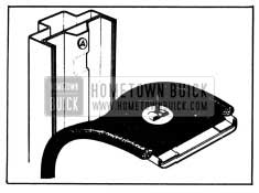
1950 Buick Attachment of Center Pillar Trim
- To install, reverse this procedure.
1950 Buick Rear Quarter Arm Rest
- Remove rear seat cushion and seat back (par. 13-21).
- Carefully loosen arm rest material from cement and retaining tabs at wheelhouse area indicated at “A,” figure 13-45.
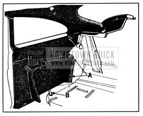
1950 Buick Rear Quarter Arm Rest and Trim
- Remove the single screw and washer at “B” securing arm rest bracket to floor pan.
- Disengage arm rest from lower retaining tab on wheelhouse and lift straight up to free from its retaining brackets.
- To install, reverse this procedure. Use “3M Trim Cement” to recement material to wheelhouse.
1950 Buick Rear Quarter Trim
- Remove rear quarter arm rest (subpar. b, above).
- Loosen and roll back rear floor carpet in area adjacent to rear quarter trim.
- Remove rear quarter, garnish and belt finishing moldings (par. 13-16, b).
- Remove rear quarter window regulator handle, using Door Handle Pliers KMO 601. See figure 13-37.
- Loosen cemented portions of trim at wheelhouse and floor areas. Also free top rear portion of trim panel from tabs which also secure headlining at “C,” figure 13-45.
- Pry loose the front edge of the trim assembly along “D” where secured with binding strip nails, and remove.
- To install, reverse this procedure. Recement material to floor and wheelhouse with “3M Trim Cement.”
Leave A Comment
You must be logged in to post a comment.