SECTION 6-D 1950 BUICK WHEEL BALANCE AND ALIGNMENT
6-26 1950 BUICK WHEEL AND TIRE BALANCE
1950 Buick wheel and tire balance is the equal distribution of the weight of the wheel and tire assembly around the axis of rotation. Wheel unbalance is the principal cause of tramp and general car shake and roughness, and contributes somewhat to steering troubles.
All wheel and tire assemblies are balanced when assembled at the factory. Tire casings and tubes are assembled with the valve stem located in line with a red mark on the sidewall of the casing, so that the weight of the valve is placed on the light side of the tire. When assembled in this manner the off-balance of the tube tends to counter-balance any off-balance of the tire. After installation of tube and tire on the wheel, the assembly is further corrected for balance, if necessary, by installing balance weights on the rim of the wheel.
The original balance of the tire and tube assembly may change as the tire wears. Severe acceleration, severe brake applications, fast cornering and side slip wear the tires out in spots and often upset the original balance condition and make it desirable to rebalance the tire, tube and wheel as an assembly. Tire and wheel assemblies should be rebalanced after punctures are repaired.
It is recommended that 1950 Buick wheel and tire assemblies be checked for balance every 5000 miles.
6-27 STATIC AND DYNAMIC BALANCE
Static Balance
Static balance (sometimes called still balance) is the equal distribution of the weight of the wheel and tire assembly about the axis of rotation in such a manner that the assembly has no tendency to rotate by itself, regardless of its position.
For example: A wheel with a chunk of dirt on the rim will always rotate by itself until the heavy side is at the bottom. Any wheel with a heavy side like this is statically out of balance. Static unbalance of a wheel causes a hopping or pounding action, commonly known as wheel tramp, which will also develop into wheel shimmy.
Dynamic Balance
Dynamic balance (sometimes called running balance) means that the wheel must be in static balance and also run smoothly at all speeds on an axis which runs through the center line of the wheel and tire, and is perpendicular to the axis of rotation.
To explain the principle of dynamic balance, let us first consider what happens when we swing a weight attached to a string. If we start to swing this weight slowly, it is apparent that the weight swings in a sharp angle with reference to the axis of rotation (the hand). But if the speed is increased, the weight climbs until the weight mass is at right angles to the axis of rotation. Now, let us apply this principle to a spinning wheel.
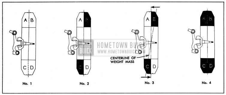
1950 Buick Static and Dynamic Balance
By referring to figure 6-30, view No. 1, it can be seen that when a wheel and tire assembly is in static balance, the sum of the weights of sections “A” and “B” is equal to the sum of the weights of sections “C” and “D”; or, in other words, the weight is equally distributed about the axis of rotation. View No. 2 is a drawing of a wheel that is in static balance because the shaded heavy point “B” is balanced by the shaded heavy point “C.” However, it can be seen that with reference to the center line, section “A” is lighter in weight than section “B,” and that section “D” is lighter in weight than section “C.”
When we start to spin this wheel, as in view No. 3, the center line of the weight masses “B” and “C” tries to get at right angles to the axis, just as the weight on the string tried to get at right angles to its axis of rotation (the hand). This tendency to get at right angles exerts a force on the wheel, as shown by the arrows. This force, in turn, tends to move the center line of the wheel and, in so doing, distorts the axis of rotation.
When the wheel has turned 180°, the forces exerted by the heavier sections “B” and “C” now tend to move the center line of the wheel in the opposite direction. In other words, the wheel tries to rock first in one direction, then in the other. The result of the movement of these unbalanced forces causes the wheel to wobble or shimmy, and the condition becomes more violent with increased speeds.
To correct this condition we must add weight to sections “A” and “D,” so they will be equal to the weight of sections “B” and “C.” Notice that this addition of weight now distributes the total weight evenly about both the axis of rotation and the center line of the wheel as seen in view No. 4. Therefore, this wheel is now both statically and dynamically balanced.
6-28 1950 BUICK WHEEL AND TIRE BALANCING PROCEDURE
Static Balancing
Static balancing is a simple procedure and can be done on any good balancing equipment of either the vertical or horizontal type.
If such equipment is not available, a simple static balancing fixture may be made from a used steering knuckle, hub, and bearings. Mount the steering knuckle solidly on edge of bench by means of suitable steel straps. Remove the felt packing from hub, wash bearing free of lubricant and adjust bearings so that a very slight looseness may be felt. When a wheel and tire assembly is mounted in a vertical position on the fixture, the heavy side will go to the bottom.
With any type of static balancing equipment the first step is to locate the light spot on the wheel and tire assembly. Mark this spot with chalk and add sufficient weight at this point to exactly balance the assembly statically. Wheel balance weights having metal clips for attachment to the flange of wheel rim are listed in 1/2, 1, 2, and 3 ounce sizes under Group 6.367 of the Master Parts List.
If a single weight will balance the wheel, one weight may be used. If more than one weight is used, the weights should be distributed equally from the light point on the same flange. See figure 6-31, views A, B, C.
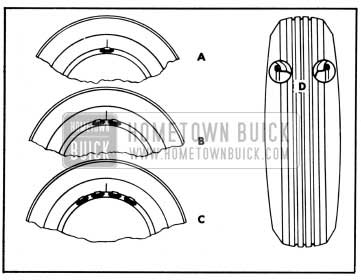
1950 Buick Location of Static Balancing Weights
Where weights are assembled to only one flange of wheel rim they should always be assembled to inside flange. When more than 3 ounces of weight is used, divide the weight equally between inside and outside flanges in order to maintain dynamic balance. See figure 6-35, view D.
In some cases wheel and tire balance does not always overcome wheel balance complaints because the brake drums themselves are out of balance. Balancing drums with wheels and tires as an assembly is not always satisfactory because the balance is destroyed when wheels and tires are removed or interchanged. On cars where trouble is experienced in maintaining proper wheel balance, it is suggested that all drums be individually checked for static balance and corrected, if necessary, as described under Brake Drum Balance (par. 8-17).
Nearly all cases of off-balance can be corrected by balancing statically. If the trouble still persists after the complete rotating assembly has been balanced statically (balance when the wheel assembly is at rest), then the assembly must be checked for dynamic balance.
Dynamic Balancing
Dynamic balancing of a wheel and tire assembly must be done on a machine designed to indicate out of balance conditions while the wheel is rotating. Since procedures differ with different machines, the instructions of the equipment manufacturer must be carefully followed.
6-29 1950 BUICK FRONT WHEEL ALIGNMENT FACTORS
1950 Buick wheel alignment is the mechanics of properly adjusting all the factors affecting the position of front wheels so as to cause the car to steer with the least effort and to reduce tire wear to a minimum.
Correct alignment of the frame is essential to proper alignment of front and rear wheels. Briefly, the essentials are that the frame must be square in plain view within specified limits, that the top and bottom surfaces of front cross member must be parallel fore and aft, and the bolt holes for front shock absorbers and lower control arm shafts must be of correct size and location. Checking frame alignment is covered in paragraph 9-2.
It should also be understood that wheel and tire balance has an important effect on steering and tire wear. If wheels and tires are out of balance, “shimmy” or “tramp” may develop or tires may wear unevenly, and give the erroneous impression that the wheels are not in proper alignment. For this reason, the wheel and tire assemblies should be known to be in proper balance before assuming that wheels are out of alignment.
Six factors must be considered in determining correct alignment of front and rear wheels. These are as follows:
Front Wheel Caster
Caster is the fore and aft angle or tilt of the king pin with reference to a line at right angle to road. See figure 6-32. When top end of king pin tilts rearward the caster is positive; when top end of king pin tilts forward the caster is negative.

1950 Buick Front Wheel Alignment Specification Chart
Front Wheel Camber
Camber is the outward or inward angle or tilt of the wheels from centerline of car, with reference to a line at right angle to road. See figure 6-32. When top of wheel tilts outward the camber is positive; when top of wheel tilts inward the camber is negative or reverse.
King Pin Inclination
King pin inclination is the inward angle or tilt of the king pin towards centerline of car, with reference to a line at right angle to road. See figure 6-32.
Front Wheel Toe-In
Toe-in is the setting of the front wheels so that the distance between them is less at the front than at the rear, when wheels are in straight ahead position. See figure 6-32.
Steering Geometry {Turning Angles)
Steering geometry is the mechanics of keeping the front wheels in proper relation to each other when making right or left turns. As the wheels are turned sideways, the inside wheel must turn through a greater angle than the outside wheel in order to compensate for the difference in turning radius of these two wheels. This is necessary to avoid sidewise scuffing of front tires on a turn. See figure 6-32.
6-30 1950 BUICK FRONT WHEEL ALIGNMENT PROCEDURE
Close limits on caster, front wheel camber, and king pin inclination are beneficial to ease of steering but require only reasonable accuracy to provide normal tire life. With the type of front suspension used, the toe-in adjustment is much more important than caster and camber in so far as tire wear is concerned. Caster and camber adjustments need not be considered unless visual inspection shows these settings to be out, or unless the car gives poor handling on the road.
In the majority of cases, services consisting of inflating tire s to specified pressure and interchanging tires at recommended intervals (par. 6-8), balancing all wheels and tires (par. 6-28), adjusting steering gear (par. 7-4), and setting toe-in correctly (subpar. e, below) will provide more improvement in car handling and tire wear than will front end alignment adjustments as usually made on front end alignment equipment.
The use of accurate front end alignment is essential to determine whether front suspension parts have been damaged by shock or accident, and to obtain correct alignment settings after new parts have been installed.
Inspection Before Checking Front Wheel Alignment
Before any attempt is made to check or make any adjustment affecting caster, camber, toe-in, king pin inclination, or steering geometry, the following checks and inspections must be made to insure correctness of alignment equipment readings and alignment adjustments.
- The front tires should have approximately the same wear and all tires must be inflated to specified pressures (par. 6-8).
- Check front wheel bearings for looseness and adjust, if necessary (par. 6-14).
- Check for run-out of wheels and tires and correct to within limit of Vs” run-out at side of tires, if necessary.
- Check wheels and tires for balance and correct if out of balance (par. 6-28).
- Check for looseness at king pins and tie rod ends; if found excessive it must be corrected before alignment readings will have any value.
- Check shock absorber action and correct, if necessary (par. 6-10).
- Car must be on a level surface and at curb weight (no passengers, no load in car, spare tires in place, and full of water, oil, and gasoline).
- Bounce car at front and rear ends several times to allow frame to come to its normal level. Check spring trim dimensions and make any correction indicated (par. 6-17 and 6-20).
- It is also advisable to check the condition and accuracy of any equipment being used to check front end alignment, and to make certain that instructions of the manufacturer are thoroughly understood.
Checking Caster and Camber Settings
Since caster and camber are both adjusted by turning the eccentric knuckle support upper pivot pin, both of these settings must be checked before changing either setting.
CAUTION: Regardless of equipment used to check caster and camber, car must be on level surface both transversely and fore and aft, and must be at curb weight. Since camber varies in proportion to the height of the front springs, it is very important that the correct spring trim dimension is maintained while checking camber (par. 6-17}.
When equipment is used _which bears against the tire or wheel rim to obtain readings, it is very essential that the tires or wheels be checked for run-out. Readings must be taken at points which have no run-out or which lie in the same plane.
Caster and camber should be within the limits shown in figure 6-32. Note that the caster angles at both front wheels need not be exactly the same but must be within 1/2 degree of each other. Likewise, the camber angles on both sides must be within 3/4 degrees of each other. If caster and camber are not within the specified limits, adjust as described below.
Adjustment of Caster and Camber
Caster and camber must be adjusted together to obtain the best average setting of each within the specified limits given in figure 6-32.
- Loosen pivot pin clamp bolt on upper end of knuckle support. Remove grease fitting from the clamped type upper pivot pin bushing. This bushing is on front end of the right pivot pin and on rear end of left pivot pin. See figure 6-33.
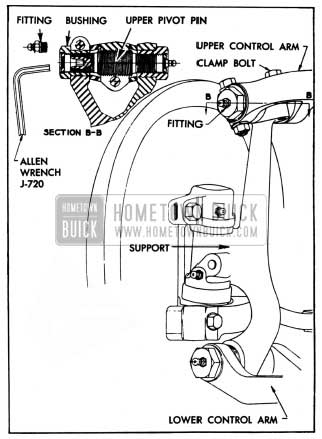
1950 Buick Steering Knuckle Support and Pivot Pins
Checking King Pin Inclination
CAUTION: When checking king pin inclination, car must be on a level surface, both transversely and fore and aft. It must be at curb weight and must be maintained at specified spring trim height while checking (par. 6-17 ).
With camber known to be within specified limits, king pin inclination should check within specified limits given in figure 6-32.
If camber is correct and king pin inclination is not correct, a bent steering knuckle support is indicated.
If camber is incorrect beyond limits of adjustment and king pin inclination is correct, or nearly so, a bent steering knuckle is indicated.
If camber and king pin inclination are both incorrect by approximately the same amounts, a bent upper or lower control arm is indicated.
There is no adjustment for king pin inclination as this factor depends upon the accuracy of the front suspension parts. Distorted parts should be replaced with new parts. The practice of heating and bending front suspension parts to correct errors is not recommended as this may produce soft spots in the metal in which fatigue and breakage may develop in service.
Checking and Adjusting Toe-In
CAUTION: Car must be at curb weight and specified trim height, with steering gear and front wheel bearings properly adjusted and no looseness at tie rod ends. See subparagraph a, above. The car should be moved forward one complete revolution of the wheels before the toe-in check and adjustment is started and the car should never be moved backward while making the check and adjustment.
- Turn steering wheel until lower spoke is vertical, with front wheels in straight ahead position.
- Measure the horizontal distance from the near edge of front boss of lower control arm shaft to the front edge of brake backing plate, on each side. Adjust tie rods, if necessary, to make measurements equal on both sides. See figure 6-34 dimensions “X.”
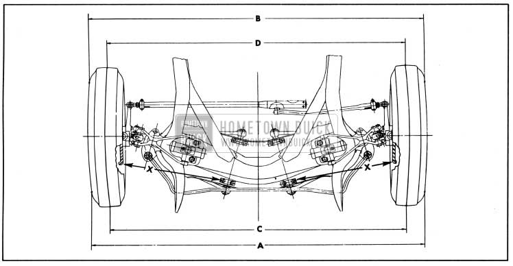
1950 Buick Front Wheel Toe-in
- Series 40-50. Decrease toe-in by turning left sleeve in same direction as wheel rotates moving forward and turn right sleeve in opposite direction. Increase toe-in by turning both sleeves in opposite direction.
- Series 70. Increase toe-in by turning left sleeve in same direction as wheel rotates moving forward and turn right sleeve in opposite direction. Decrease toe-in by turning both sleeves in opposite direction.
CAUTION: Left and right adjusting sleeves must be turned exactly the same amount but in opposite directions when changing toe-in, in order to maintain front wheels in straight ahead position when steering wheel lower spoke is straight down.
- After correct toe-in is secured tighten clamp bolts securely. On Series 70, make sure that tie rod clamps are within 1/8″ of end of rods and that ear of clamp overlaps slot in tube not less than 1/16″ See figure 6-35.
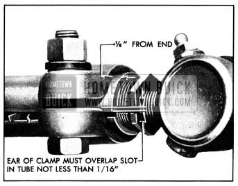
1950 Buick Correct Position of Tie Rod Clamp
Checking Steering Geometry (Turning Angles}
CAUTION: Be sure that caster, chamber, and toe-in have all been properly corrected before checking steering geometry. Steering geometry must be checked with the weight of the car on the wheels.
- With the front wheels resting on full floating turntables, turn wheels to the right until the outside (left) wheel is set at 20 degrees. The inside (right) wheel should then set at angle specified in figure 6-32.
- Repeat this test by turning front wheels to the left until the outside (right) wheel sets at 20 degrees; the inside (left) wheel should then set at angle specified in figure 6-32.
- Errors in steering geometry generally indicate bent steering arms, but may also be caused by other incorrect front end factors. If the error is caused by a bent steering arm it should be replaced. Replacement of such parts must be followed by a complete front end check as described above.
Leave A Comment
You must be logged in to post a comment.