SECTION 2-F 1950 BUICK COOLING AND OILING SYSTEMS SERVICE
2-24 FILLING COOLING SYSTEM
An engine should never be run with the coolant level so low as to cause couldn’t to boil out of the radiator as damage to the engine will result. It is unnecessary and undesirable, however, to remove the radiator cap and check the coolant level whenever the car stops at a filling station for gasoline or oil, since the engine is usually hot at such times.
The coolant level may be considered correct so long as the temperature gauge stays within the operating range marked on dial face. Normal temperature readings will be from 160° to 200°, but in extremely hot weather the reading may go as high as 212° without affecting the efficiency of the engine or being an indication of overheating. It must be remembered that in the Buick pressure cooling system water boils at a higher temperature than at atmospheric pressure. The following table shows the boiling points with different coolants.
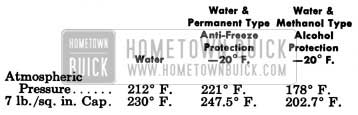
1950 Buick Cooling System Boiling Points
The coolant level should be checked when the engine is cold and only enough water should be added to bring the level to the line marked “Filling Level Cold” stamped about 11,4″ below top of head tank on rear side. CAUTION: Radiator cap should not be removed when engine is HOT because releasing the pressure may cause the 1950 Buick cooling system to boil, with resultant loss of water or anti-freeze solution. Filling radiator when hot, or filling above the level line, may cause loss of coolant through the overflow pipe.
If it is necessary at any time to remove the radiator cap when the 1950 Buick cooling system is hot, do not remove the cap quickly. Rotate the cap counterclockwise until a stop is reached. In this position, pressure and vapors will escape through the overflow pipe. Leave cap in this position until all the pressure has been released, then turn cap forcibly past the stop and remove. Unless this precaution is used, the coolant may boil when pressure is released and some of it may be ejected from the filler neck of the radiator, causing injury to persons or damage to the car finish.
Never pour cold water into the radiator when coolant is extremely low and the engine hot. Such a sudden change in temperature may result in cracking the water jackets. It is advisable to allow the hot engine to cool for ten or fifteen minutes before adding cold water, then run engine at idle while slowly adding water.
2-25 FLUSHING 1950 BUICK COOLING SYSTEM AND USE OF RUST PREVENTATIVES
Draining and Flushing
It is advisable to drain and flush the engine cooling system twice a year. This should be done when the anti-freeze solution is added in the fall and again when it is removed in the spring.
Flushing with clean water is helpful in getting rid of fine rust which remains in suspension when agitated. In the simplest method of flushing the 1950 Buick cooling system, the drain cocks and heater control valve are opened and, with the engine running at low speed, the radiator is kept filled by a stream of water from a hose inserted in radiator filler neck. The objection to this method is that cold water from the hose may close the thermostat and prevent thorough flushing of the water jacket. A more positive method is to fill the cooling system with clean water, run the engine long enough to open the thermostat for complete circulation through the system, then completely drain the 1950 Buick cooling system before sediment has a chance to settle.
For the most complete removal of loose rust from radiator and water jacket, pressure flushing with an air-and-water gun (such as Radiator Flusher J 708A) may be used. When using this method, remove both radiator hoses and the radiator thermostat, then reverse flush the radiator and the engine separately.
Do not use cleaning chemicals which loosen scale unless the 1950 Buick cooling system is reverse flushed after use because loosened scale will plug the radiator water passages.
To completely drain the 1950 Buick cooling system, proceed as follows to insure draining of heater and defroster cores :
- Open heater control valve to wide open (heat on) position.
- Disconnect heater return hose at upper connection_ on water pump and lower end of hose to floor level.
- Open radiator and cylinder block drain cocks and remove radiator cap.
NOTE: On Dynaflow car, if 1950 Buick cooling system is being drained for storage where freezing may occur it is advisable to also disconnect lower hose at transmission oil cooler.
To completely refill 1950 Buick cooling system after draining, use the following procedure to insure filling of heater and defroster cores:
- Close both drain cocks and connect heater hose to water pump.
- Disconnect heater hose at engine thermostat housing, fill system until coolant flows out of heater hose when held at thermostat housing level, then connect hose to housing and complete the refilling.
- Start engine and run until thermostat opens, then accelerate engine a few times.
- Fill radiator to line marked COLD FILLING LEVEL and install radiator cap.
Use of Rust Preventatives
Buick strongly recommends the use of rust preventatives such as 1950 Buick Cooling System Rust Preventative, Group 8.766 Part #980640, which is available through Buick Parts Warehouses. In addition to keeping the 1950 Buick cooling system free from rust this preparation is also effective in eliminating a squealing noise which sometimes develops in water pump at slow idle speed.
Rust preventative should be added to the coolant of all new cars during the initial servicing, and this treatment should be repeated once a year after the anti-freeze solution has been drained out and 1950 Buick cooling system has been thoroughly flushed. Rust preventative should be added to the coolant of used cars also, after the 1950 Buick cooling system has been thoroughly flushed.
When used in the correct proportions of one ounce per gallon of water, this rust preventative first forms a milky white emulsion with the water and after several days use deposits a protective coat over the metal surfaces in the 1950 Buick cooling system. This coating does not affect the efficiency of the 1950 Buick cooling system, but, by preventing rust or corrosion, maintains the 1950 Buick cooling system at its original efficiency.
This solution is not a cleaning agent and has no anti-freeze properties. It does not interfere with the functioning of approved anti-freeze solutions, and its functioning is not affected by them. Its sole purpose is the prevention of rust and corrosion.
Rust preventative solutions, 0ther than the one mentioned above, may be purchased from reliable sources of supply and if used in accordance with the manufacturer’s specifications should give equally satisfactory results.
Practically all anti-freeze solutions contain an inhibitor or rust preventative. Therefore, caution should be exercised when adding rust preventative to such solutions because an excessive quantity of rust preventative will deteriorate rubber hose connections.
2-26 USE OF ANTI-FREEZE SOLUTIONS
Types of Anti-Freeze Solutions
In selecting anti-freeze solutions for winter operation the local conditions and type of service must be considered. Anti-freeze solutions are of two general types, namely: Volatile solutions such as the alcohols and non-volatile solutions such as ethylene glycol.
The volatile type solutions are lower in first cost but are subject to loss through evaporation, especially on heavy runs or when warm days are encountered. Unless the solution is tested at frequent intervals and sufficient new material is added to replace the loss by evaporation, the engine or radiator, or both, are liable to damage by freezing. The car finish is damaged by contact with alcohol solutions or vapors; therefore, any such material accidentally spilled on the finish must be flushed off immediately with a large quantity of clean, cold water.
Since alcohol solutions are volatile, they cannot be used with a radiator thermostat having a temperature calibration higher than standard to improve car heater performance.
The non-volatile or “permanent” type solutions are higher in first cost but are not subject to loss through evaporation. Unless loss is incurred through leakage followed by the additions of water, this type of solution maintains the freezing protection originally established without addition of fresh material. When using this type of anti-freeze solution, care must be taken to prevent seepage of solution into the cylinder bores where it will cause gumming and sticking of moving parts.
Ethylene glycol anti-freeze solutions have a somewhat higher boiling point than alcohol solutions and consequently may be operated at a high temperature. This permits the use of a higher temperature radiator thermostat, resulting in more effective performance of the car heater.
Every anti-freeze solution must be used in accordance with the instructions and in proportions specified by the anti-freeze manufacturer. ‘The proportions must be selected as specified for the lowest temperature at which protection against freezing will be required.
Unsatisfactory Anti-Freeze Solutions
The following solutions have been found to be unsatisfactory for use in automobile cooling systems: Salt solutions such as calcium or magnesium chloride, sodium silicate, etc.; honey, glucose, sugar solutions, oils or kerosene, untreated glycerine, untreated ethylene glycol.
Preparation of 1950 Buick Cooling System for Anti-Freeze Solution
It is very important to make certain that the 1950 Buick cooling system is properly prepared before an anti-freeze solution is installed; otherwise, loss of solution through leakage may occur or seepage may result in damage to the engine.
The 1950 Buick cooling system should be drained and flushed as described in paragraph 2-25. The use of additional rust preventatives or inhibitors is not recommended when using G.M. antifreeze solutions or other anti-freeze preparations that have been chemically treated or compounded for use in automotive cooling systems since these preparations have rust preventative properties.
Inspect the water pump, radiator core, radiator and heater hose connections, drain cocks, water jacket plugs, and edge of cylinder head gasket for evidence of leakage. Inspection should be made with 1950 Buick cooling system cold because small leaks which may show dampness or dripping when cold can easily escape detection when the engine is hot, due to the rapid evaporation of the leakage. Tell-tale stains of grayish-white or rusty color, or dye stains from anti-freeze, at joints in 1950 Buick cooling system are almost always sure signs of small leaks even though there appears to be no dampness.
Tighten hose clamps if leakage occurs at hose connections. Replace any deteriorated hose. All points of leakage should be corrected before the anti-freeze solution is placed in 1950 Buick cooling system.
If there is indication of seepage at cylinder head gasket, the cylinder head bolts should be carefully checked for proper tightness as described in paragraph 2-16. The cylinder head bolts must not be excessively tightened, however, as distortion of cylinder bores will result.
Testing Anti-Freeze Solutions
Use only hydrometers which are calibrated to read both the specific gravity and the temperature, and have a table or other means of converting the freezing point at various temperatures of the solution. Disregarding the temperature of the solution when making the test may cause an error as large as 30°F. Care must be exercised to use the correct float or table for the particular type of anti-freeze being tested.
It is not practical to mix different types of anti-freeze materials in the same 1950 Buick cooling system since it will not be possible to determine the freezing point of such a solution with a hydrometer.
2-27 FAN BELT ADJUSTMENT OR REPLACEMENT
A tight belt will cause rapid wear of the generator and water pump bearings. A loose belt will slip and wear excessively, causing overheating of the engine and unsteady generator output. A loose belt will also cause a noise similar to spark rap at high speed. A fan belt which is cracked or frayed, or which is worn so that it bottoms in the pulleys, should be replaced.
The fan belt may be replaced by slightly loosening upper and lower generator clamp bolts shown at “A”, “B”, and “C” in figure 2-35 so that generator can be moved in toward the cylinder block to provide maximum slack.
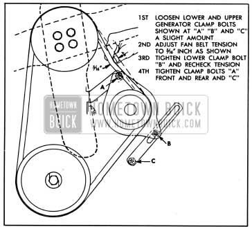
1950 Buick Fan Belt Adjustment
The new or old belt must be adjusted so that it will deflect approximately 5/16″ with a normal thumb pressure applied midway between the generator and fan pulleys. The steps- for adjustment are shown in figure 2-35.
2-28 RADIATOR THERMOSTAT INSPECTION AND TEST
A sticking radiator thermostat will prevent the 1950 Buick cooling system from functioning properly. If the thermostat sticks in the open position, the engine will warm up very slowly. If the thermostat sticks in the closed position, overheating will result.
The thermostat may be removed for inspection and test by partially draining the 1950 Buick cooling system and disconnecting the cylinder outlet from the thermostat housing.
When the thermostat is cold, the valve should be fully seated. If valve does not seat, or the bellows portion is distorted or damaged, the thermostat should be replaced.
If thermostat valve seats when cold, test the thermostat for correct opening temperature by immersing the unit and a thermometer in a container of water over a heater. While heating the water do not rest either the thermometer or thermostat on bottom of container as this will cause them to be at higher temperature than the water. Agitate the water to insure uniform temperature of water, thermostat and thermometer.
The standard thermostat (151°) valve should start to leave its seat at a temperature of 148° F. to 155° F., and should be fully open at a temperature not in excess of 176° F. On the high temperature (182°) thermostat which may be installed to improve car heater performance, the valve should start to leave its seat at a temperature of 178° F. to 185° F., and should be fully open at a temperature not in excess of 211° F. If thermostat does not operate at specified temperatures it should be replaced as it cannot be adjusted.
2-29 WATER PUMP SEAL REPLACEMENT
Removal and Disassembly of Water Pump
- Drain 1950 Buick cooling system, being sure to drain into a clean container if anti-freeze solution is to be saved.
- Remove fan belt and disconnect all hoses from water pump.
- Remove water pump and also remove pump body to thermostat housing rubber hose if it is in doubtful condition.
- Remove fan blade, spacer, and pulley from hub on water pump shaft.
- Remove water pump cover and remove impeller from pump shaft, using a suitable puller. A puller with two hooks is preferred, however, a puller with three hooks may be used.
- Remove carbon washer, spring and bellows from the brass sleeve that is pressed into pump housing. It is not necessary to remove the brass sleeve if it is in good condition. If sleeve is doubtful, however, remove by driving it out with a punch inserted through vent holes in pump body.
- Thoroughly clean the pump body to remove rust, old gasket, etc. Do not soak in cleaning solvent as this may leak into bearing and destroy the lubricant.
Installation of Seal Assembly and Installation of Water Pump
- If the old brass seal sleeve was removed from pump body during disassembly, carefully press the sleeve of new seal assembly into place, using a thick walled tube of proper inside and outside diameters to bear fully against flange of sleeve. It is not necessary to remove the other seal parts from sleeve.
If old sleeve was not removed, separate the new seal sleeve from seal bellows by soaking in hot water to soften the cement used to hold seal parts together for ease of handling. Install the bellows, spring, and carbon washer in the sleeve in pump body, with the low-shouldered side of washer outward. Be careful to engage the two notches in washer with the driving dents in brass sleeve. See figure 2-36.
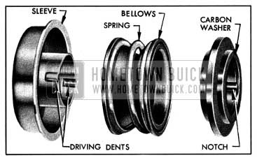
1950 Buick Water Pump Seal Disassembled
- Coat the face of carbon washer and impeller hub with rust preventative or Seco Oil, then support pump assembly on the fan end of shaft and press the impeller on inner end of shaft until rear face of impeller is flush with end of shaft.
- Install pump cover, using a new gasket cemented in place. Install fan pulley, spacer, and blade and tighten attaching screws securely.
- Install pump assembly on engine using new gasket, and a new pump body to thermostat housing hose if necessary.
- Connect all hoses, fill cooling system and check for water leaks at connections.
- Install fan belt and adjust to proper tension (par. 2-27).
2-30 OIL PUMP REPAIRS
When an oil pump is removed for repairs the following procedure must be used to inspect parts and assemble pump in order to insure adequate oil pressure when the work is completed.
- Remove screen and float assembly from pump cover by removing retaining cotter pin. Wash the screen thoroughly in kerosene or other solvent and apply light air pressure through the inlet tube to dislodge dirt from the outer surface of screen.
- Check oil pressure valve to see if it is free in pump body. Also, check hole in body to see that it is not oversize and that the valve fits hole throughout length. Check spring to see that it is not collapsed, worn on its side, or broken. Replace with a new spring if in doubt.
- Check position of gear on shaft. The measurement should be same as shown in figure 2-37.
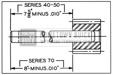
1950 Buick Position of Gear on Shaft
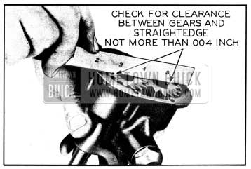
1950 Buick Checking Clearance of Gears at Cover
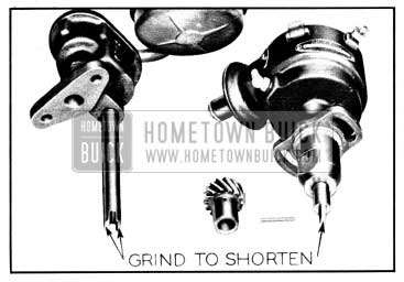
1950 Buick Parts to be Ground for Shaft End Clearance
Leave A Comment
You must be logged in to post a comment.