SECTION 8-A 1950 BUICK BRAKE SPECIFICATIONS, DESCRIPTION, OPERATION, SERVICE RECOMMENDATIONS
8-1 1950 BUICK BRAKE SPECIFICATIONS
1950 Buick Brake Tightening Specifications
Use a reliable torque wrench to tighten the parts listed, to insure proper tightness without straining or distorting parts. These specifications are for clean and lightly lubricated threads only; dry or dirty threads produce increased friction which prevents accurate measurement of tightness.
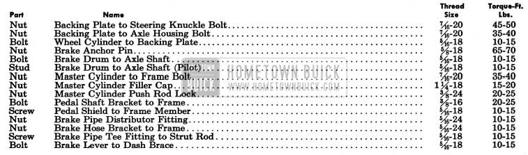
1950 Buick Brakes Tightening Specifications
1950 Buick Brake Specifications
1950 Buick Brake Specifications
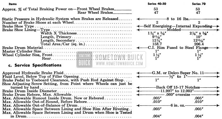
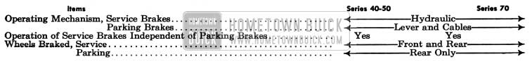
1950 Buick Brakes General Specifications
Service Specifications (see above)
8-2 DESCRIPTION OF 1950 BUICK BRAKES
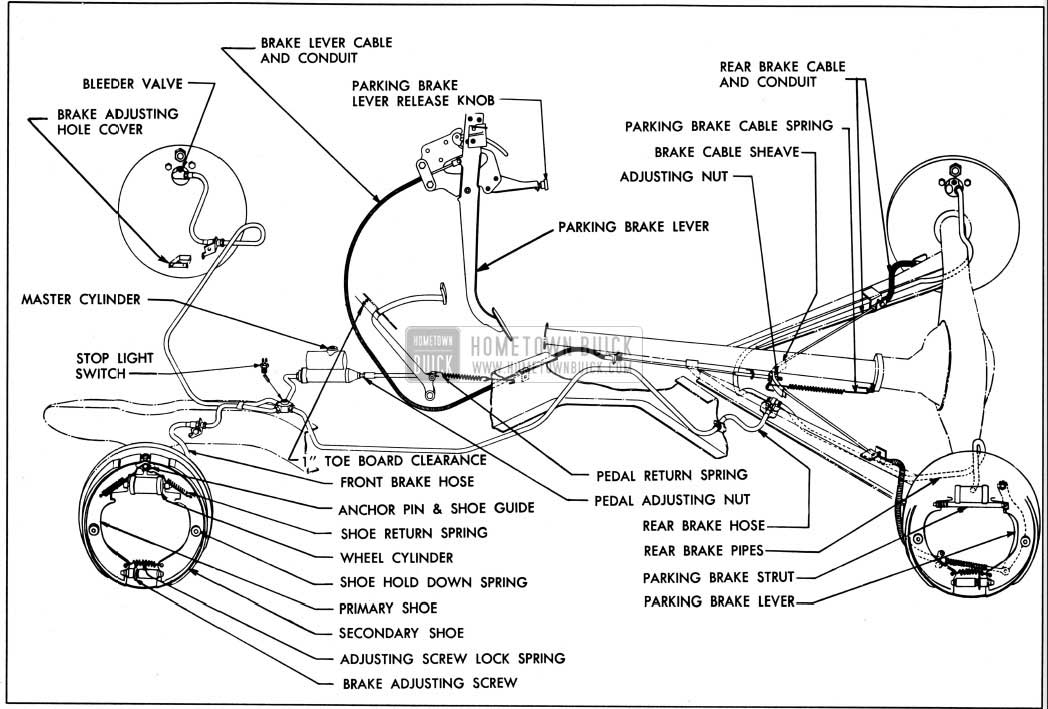
The 1950 Buick brake mechanism includes a hydraulically operated service brake system and a mechanically operated parking brake system. The hydraulic service brake system simultaneously applies the 1950 Buick brake shoes at all four wheels; the parking brake system applies the brake shoes at rear wheels only. Either brake system can be operated independently of the other. See figure 8-1.
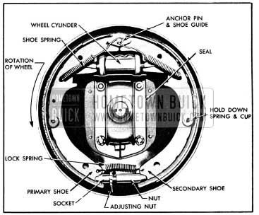
1950 Buick Front Wheel Brake Assembly-Left
1950 Buick Wheel Brake Assembly
The 1950 Buick brake assembly at each wheel uses a primary (front) and a secondary (rear) brake shoe of welded steel construction with molded lining attached by tubular rivets.
The 1950 Buick brake shoes are retained at the upper ends by an anchor pin and shoe guide mounted on the brake backing plate, and heavy coil springs hold the shoes to the anchor pin. A, hold down spring near the middle holds each shoe against the backing plate while allowing free movement of the shoe. The lower ends of the brake shoes are joined together by an adjusting screw and spring but are free to float since they are not attached to the backing plate. See figure 8-1.
A hydraulic brake wheel cylinder (fig. 8-3), which is mounted on brake backing plate between upper ends of brake shoes, expands the brake shoes in each brake assembly during application of the service brakes. During application of parking brakes, a strut and brake lever expands the brake shoes in each rear brake assembly only. The upper end of brake lever is pivoted to the web of the secondary shoe, the strut connects brake lever to the primary shoe, and the rear brake cable is attached to lower end of brake lever. The coil springs which connect brake shoes to the anchor pin retract the shoes when either the service or parking brakes are released. See figure 8-11.
1950 Buick Hydraulic Brake Wheel Cylinders
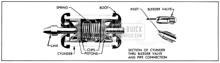
Each wheel cylinder contains two pistons and two rubber cups which are held in contact with the pistons by a central coil spring to provide a fluid-tight seal. The inlet port for 1950 Buick brake fluid is located between the pistons so that when fluid pressure is applied both pistons move outward toward the ends of wheel cylinder. The pistons impart movement to the brake shoes by means of connecting links which seat in pistons and bear against webs of shoes. Rubber boots enclose both ends of cylinder to exclude foreign matter. A valve for bleeding the brake pipes and wheel cylinder is located above the inlet port. See figure 8-3.
1950 Buick Wheel Cylinder-Sectional View
1950 Buick Brake Drums
The 1950 Buick brake drums consist of cast iron rims fused to pressed steel flanges. The cast iron rims provide ideal braking surfaces and increased 1950 Buick brake lining life. An external web around the circumference prevents distortion and aids in dissipation of heat.
1950 Buick Hydraulic Brake Master Cylinder
The 1950 Buick master cylinder performs three functions. (1) It maintains a constant volume of fluid in the hydraulic system at all times, regardless of expansion due to heat or contraction due to cold. (2) It transmits the pressure of the brake pedal equally to the wheel cylinders (and 1950 Buick brake shoes) at all wheels through fluid pressure built up in its cylinders. (3) It acts as a pump during bleeding of the hydraulic system.
The master cylinder is mounted on the inside of left front frame side rail and is operated by the 1950 Buick brake pedal through an adjustable push rod. See figure 8-2.
1950 Buick Brake Mechanism Layout
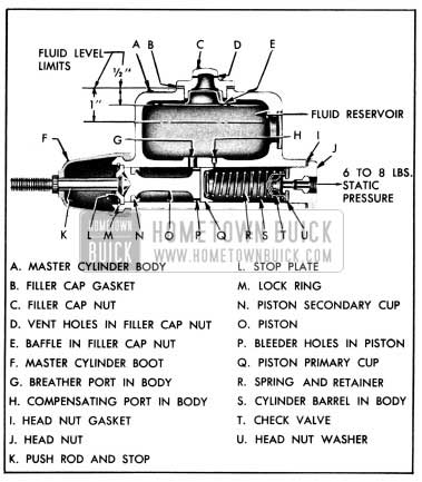
The master cylinder body (A) consists of a fluid reservoir cast integral with a cylinder barrel (S) which is machined to house the working parts. See figure 8-4.
1950 Buick Master Cylinder-Sectional View
A breather port (G) and a compensating port (H) permit passage of fluid between reservoir and cylinder barrel under certain operating conditions. The reservoir is closed at the top by a gasket (B) and a vented filler cap nut (C) containing a baffle (E) to prevent loss of fluid through the vent holes (D).
The outlet end of the cylinder barrel is closed by a head nut (J) and gasket (I). The opposite end of cylinder barrel is closed by a stop plate (L) through which a push rod (K) extends to actuate the piston (O). The outer end of the double-headed piston is provided with a rubber cup (N) to provide a fluid-tight seal, and a rubber boot (F) closes the end of the cylinder barrel to exclude foreign matter. A check valve (T) is held in place against a rubber washer (U) on the head nut by a coil spring (R) which also holds a rubber cup (Q) against the inner end of the piston. See figure 8-4.
1950 Buick Parking Brake Lever and Cables
The 1950 Buick parking brake mechanism consists of a foot operated lever and cables which operate the rear wheel brake shoes only. The parking brake lever located on left side of body cowl, will automatically lock to hold parking brakes applied when the lever is pushed forward. The brakes are released by pulling the release knob on the parking lever.
A conduit enclosed cable extends from the parking brake lever to a sheave or equalizer located near the rear end of torque tube. Another cable runs through the sheave to the brake lever in each rear brake assembly so that when the parking brakes are applied the rear brake cable applies equal pressure to the brake shoes at both rear wheels. An adjustment to take up slack is provided where the 1950 Buick brake lever cable passes through the brake cable sheave. A spring attached to the sheave pulls the cables rearward to assure full release when parking brake lever is in released position. See figure 8-2.
8-3 OPERATION OF HYDRAULIC SERVICE BRAKES
When Brakes are Released
When the 1950 Buick brake pedal is in fully released position the master cylinder piston (O) is held against the stop plate (L) by the coil spring (R) which also holds the check valve (T) against the rubber washer (U) on head nut (J) with sufficient pressure to maintain 8 to 16 pounds static pressure in brake pipes and wheel cylinders. With piston against stop plate the compensating port (H) is not covered by the piston primary cup (Q) and the breather port (G) is also open, so that the cylinder barrel (S) is completely filled with fluid from the reservoir. See figure 8-4.
The static pressure maintained in the lines and wheel cylinders is not sufficient to operate the 1950 Buick brake shoes, therefore the shoes are fully released and held in contact with the anchor pins by the 1950 Buick brake shoe springs. See figure 8-1.
Application of 1950 Buick Brakes
When the 1950 Buick brake pedal is depressed to apply service brakes, the push rod (K) forces the master cylinder piston ( 0) and primary cup (Q) toward the head nut (J). As soon as the primary cup covers the compensating port (H), pressure is built up in the cylinder barrel (S) and fluid is forced through holes in the check valve (T) into the pipes leading to all wheel cylinders. See figure 8-4.
The 1950 Buick brake fluid enters each of the wheel cylinders (fig. 8-3) causing the cylinder pistons and connecting links to move outward and force the 1950 Buick brake shoes into contact with the drums. This part of the brake action is accomplished with very light pressure on the pedal. Since the pressure must be equal in all parts of the hydraulic system, no braking action can take place until all of the shoes are in contact with the drums; therefore, the system is self-equalizing. As pressure on 1950 Buick brake pedal is increased, greater hydraulic pressure is built up within the master cylinder barrel and wheel cylinders, and consequently greater force is exerted against all 1950 Buick brake shoes.
As the 1950 Buick brake shoes come in contact with the drums, on forward motion, the energy of the turning drums is imparted to the primary shoes which then actuate the secondary shoes so that all shoes are forced against the drums with greater pressure than that provided by the hydraulic system. This self-energizing principle gives maximum braking power at the wheels with relatively light pressure on the 1950 Buick brake pedal.
When the car is being slowed down by the brakes, a transfer of weight takes place from the rear to the front end of car. The quicker the stop the greater the transfer of weight. This transfer of weight to the front wheels tends to keep the front wheels turning, consequently more braking power is required at front wheels in order to equalize the braking effect at front and rear wheels. To provide greater braking power at the front wheels, the front wheel cylinders are larger in diameter than the rear wheel cylinders. Braking power at front wheels is approximately 53% and at rear wheels approximately 47%.
Slow Release of 1950 Buick Brakes
As the 1950 Buick brake pedal is released the pedal and push rod are retracted by pedal return spring, thereby relieving pressure on master cylinder piston and consequently relieving pressure in the master cylinder barrel, 1950 Buick brake pipes, and wheel cylinders.
The master cylinder spring (R) forces the piston (O) and piston primary cup (Q) to follow the retracting push rod (K). See figure 8-4. At the same time, the brake shoe springs pull the shoes clear of 1950 Buick brake drums thereby forcing wheel cylinder pistons inward, which forces fluid out of cylinders back to the master cylinder.
Returning fluid pushes check valve (T) away from the rubber washer (U) on head nut (J) as it enters master cylinder barrel (S), however, the master cylinder spring (R) maintains sufficient pressure on the check valve to provide 8 to 16 pounds static pressure in brake pipes and wheel cylinders after brakes are fully released.
When 1950 Buick brakes are fully released, the master cylinder piston must bear against the stop plate (L) so that the compensating port (H) will not be covered by the piston primary cup (Q). The open compensating port permits a flow of fluid from reservoir into the cylinder barrel in the event that fluid was lost by leakage during brake application.
Quick Release of 1950 Buick Brakes
The action in quick release is generally the same as in the slow release described above, except for a compensating action in the master cylinder.
The piston (D) and primary cup (Q) return to the “released'” position much faster than the fluid in 1950 Buick brake pipes returns to master cylinder barrel (S). A momentary vacuum is created in the space between primary cup and head nut which causes additional fluid to flow into and fill this space through the bleeder holes (P) in piston and past the lip of primary cup. This additional fluid is supplied through the breather port (G) . When the piston reaches the stop plate (L) and the compensating port (H) is uncovered by the primary cup, surplus fluid returns to reservoir through the compensating port.
Action During Bleeding Operation
When 1950 Buick brake pedal is depressed during the bleeding operation (par. 8-9) fluid is forced out of master cylinder through the check valve (T), through brake pipes to wheel cylinder being bled. Since no pressure is built up in wheel cylinder there is no return of fluid to master cylinder when brake pedal is released. The master cylinder barrel (S) is replenished with fluid which flows from reservoir through breather port (G) , through bleeder holes in piston ( P) , and past edges of primary cup (Q). See figure 8-4.
8-4 1950 BUICK BRAKES SERVICE RECOMMENDATIONS
Break-In of New Brake Shoe Linings
Under no circumstances should the brakes be severely applied on a new car or immediately after installation of new brake shoes or linings. Severe applications may permanently injure new brake linings and may score brake drums. When linings are new they must be given moderate use for several days until nicely burnished.
Maintaining Fluid Level-Periodic Flushing
Proper fluid level must be maintained in master cylinder reservoir at all times to prevent entrance of air into hydraulic system. See paragraph 1-1 or 8-8.
It is recommended that the entire hydraulic system be thoroughly flushed and new fluid installed every 15,000 miles. See paragraph 8-10.
1950 Buick Brake Shoe Adjustment and Inspection
For average driving conditions, brakes should be adjusted for wear whenever the 1950 Buick brake pedal goes to within 2″ of toe board. If a car is habitually driven at high speed, however, adjustment should be made if pedal pad goes to within 3″ of toeboard when brakes are cold. Heat generated on high speed stops will expand brake drums, permitting pedal pad to travel closer to toeboard.
1950 Buick brakes should be promptly adjusted or otherwise corrected whenever the action becomes unduly severe, erratic, or uneven. Brake shoe linings should not be permitted to wear down until rivets contact drums because drums will be scored. As car mileage approaches the point where relining may be required it is advisable to remove one or more drums for inspection of lining in order to avoid the possibility of damaging brake drums.
Leave A Comment
You must be logged in to post a comment.