SECTION 10-E 1950 BUICK CRANKING (STARTER) SYSTEM
10-31 THE 1950 BUICK CRANKING (STARTER) SYSTEM
General Description
The 1950 Buick cranking system permits the engine to be cranked and started automatically, after the ignition has been turned on, by pressing down on the accelerator pedal. The 1950 Buick cranking motor circuit is automatically opened and the cranking motor is disengaged from the flywheel ring gear as soon as the engine starts running and the accelerator pedal is released.
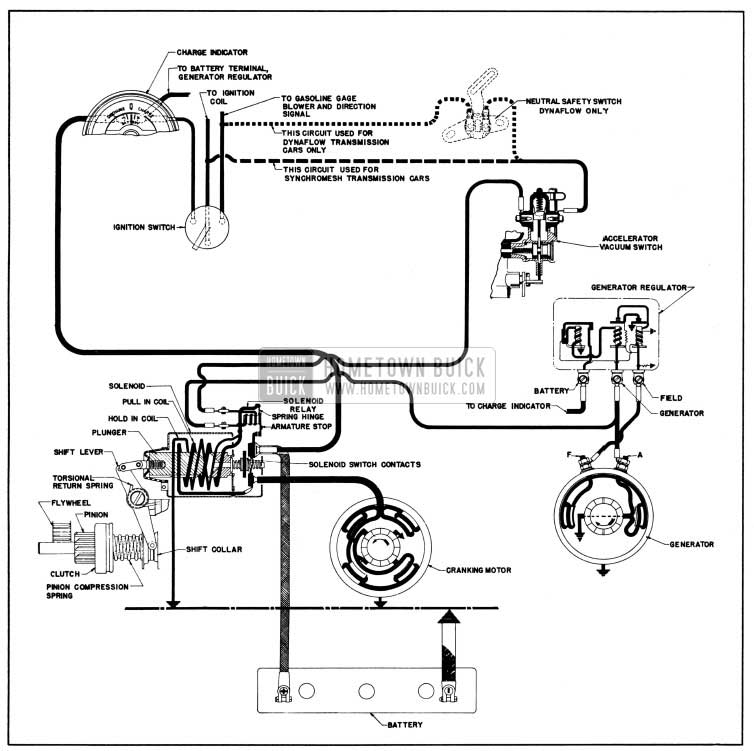
The units comprising the 1950 Buick cranking system (fig. 10-28) are as follows:
1950 Buick Cranking System Circuits
- Battery and battery cables (par. 10-14).
- 1950 Buick Cranking motor, including the drive assembly which engages the flywheel ring gear during cranking operation (par. 10-35) .
- 1950 Buick Cranking motor solenoid switch, mounted on 1950 Buick cranking motor, for shifting drive assembly and closing the motor circuit. The switch includes a relay for operating the solenoid (par. 10-35).
- Accelerator vacuum switch, mounted on the carburetor and operated by both the throttle shaft and engine vacuum. This switch permits control of 1950 Buick cranking system by the accelerator pedal (par. 10-32 and 10-33).
- Generator windings, which are used for completing the vacuum switch and solenoid relay magnet coil circuit to ground.
- Charge indicator, ignition switch, and necessary wiring to connect the various units.
- Neutral safety switch, only on cars equipped with Dynaflow Drive. This switch is connected in series with the solenoid switch relay to prevent cranking of engine except when the transmission control lever is in either the neutral (N) or parking (P) position.
Operation of 1950 Buick Cranking System
After the ignition switch is turned on, the cranking system is set in operation to start the engine by pressing down on the accelerator pedal. This causes the throttle to open and the accelerator vacuum switch contacts to close, thereby allowing current to flow from the battery through the ignition switch, vacuum switch, solenoid switch relay windings, and generator windings to ground. See figure 10-28. NOTE: On Dynaflow Drive cars, the transmission control lever must be in neutral (N) or parking (P) position so that neutral safety switch is closed.
Completion of this control circuit causes the solenoid switch relay contacts to close. Current from the battery then flows through the “pull-in” and “hold-in” coils of the solenoid, magnetizing the solenoid. The plunger is pulled into the solenoid so that it shifts the drive pinion into engagement with flywheel ring gear and closes the solenoid switch contacts.
The closing of the solenoid switch contacts causes the motor to crank the engine and also cuts out the “pull-in” coil of the solenoid, the magnetic pull of the “hold-in” coil being sufficient to hold the pinion in mesh after the shifting has been performed. This reduces the current consumed by the solenoid while the 1950 Buick cranking motor is operating.
Normally, as soon as the engine starts running and accelerator pedal is released, the manifold vacuum causes the accelerator vacuum switch to break contact- and open the relay circuit. This causes the solenoid switch relay contacts to open, which breaks the solenoid circuit. A return spring on the shift lever stud allows the solenoid switch to open and then disengages the drive pinion from flywheel ring gear.
Under conditions where the throttle does not return to idle position, or engine vacuum is not sufficient to cause the accelerator vacuum switch to break contact, the increased speed of the generator results in generating a voltage which prevents the current passing through the magnet coil of the solenoid switch relay from continuing its flow through the generator to ground, therefore the relay points open to break the solenoid circuit.
In cold weather, if the first explosions are too feeble to keep the engine turning over, the manifold vacuum is not sufficient to cause the accelerator vacuum switch to break contact, and neither does the generator develop sufficient voltage to cause the relay points to open. The 1950 Buick cranking system therefore remains in operation until the explosions are strong enough to keep the engine running.
When the engine is running, there are three separate means of preventing the cranking system from being operated by movement of the accelerator pedal: (1) Manifold vacuum acting on accelerator vacuum switch. (2) Mechanical lockout in the accelerator vacuum switch. (3) Blocking effect of generator voltage on solenoid relay.
10-32 1950 BUICK ACCELERATOR VACUUM SWITCH-ON CARTER CARBURETOR
Description and Operation
The accelerator vacuum switch used on the Carter carburetor is built into the body flange in position to be operated by the throttle shaft.
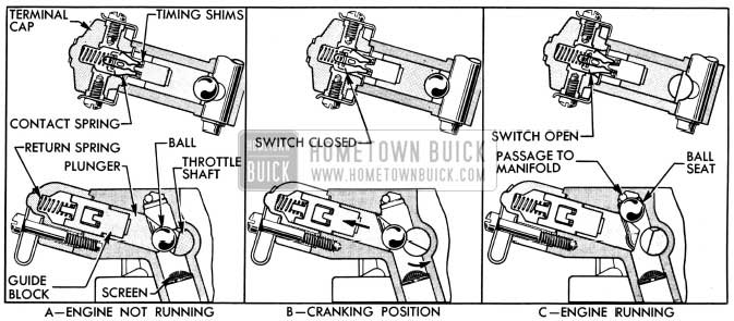
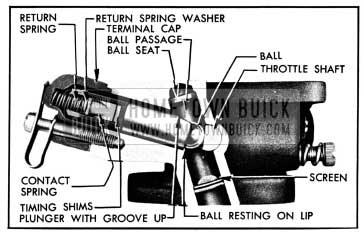
The switch consists of a special stainless steel ball, plunger, guide block, W-shaped contact spring, and return spring housed in a passage in body flange which is closed by a terminal cap containing two contacts. When the engine is not running and throttle is closed, the ball rests on a lip on the lower end of switch plunger and bears against a flat spot on the throttle shaft. The plunger, guide block, and contact spring are held in a down position by the return spring so that the contact spring does not touch the contacts in terminal cap. See figure 10-29, view A.
1950 Buick Carter Accelerator Vacuum Switch Operation
When the accelerator is depressed with engine stopped and ignition switch turned on, the flat spot on throttle shaft acts as a cam to push the switch ball, plunger, guide block, and contact spring upward until the contact spring touches both contacts in terminal cap. This closes the solenoid relay circuit and puts the 1950 Buick cranking system into operation. See figure 10-29, view B.
When the engine starts, manifold vacuum acts on the switch ball and as soon as the accelerator pedal is released the ball is drawn upward away from throttle shaft. The return spring then pushes the contact spring downward, thus breaking the circuit and causing the 1950 Buick cranking system to stop operating. See figure 10-29, view C. As long as engine continues running the switch ball is held against its seat in throttle body by manifold vacuum; therefore movement of throttle cannot cause switch to make contact. As soon as engine stops, the ball drops to the starting position.
It is very important that switch contact is made when throttle valve is opened between 30 to 45 degrees, to assure proper starting conditions. If the switch makes contact too early the throttle will not be opened sufficient to give a good cold start. If the switch makes contact too late the throttle will be opened too far, which may cause gear clash as well as hard starting due to unloading of carburetor choke by the throttle mechanism. See subparagraph b, below.
Checking 1950 Buick Vacuum Switch Timing
CAUTION: If carburetor is installed on engine make certain that transmission is in neutral and parking brake is applied.
- If carburetor is installed on Dynaflow car make certain that throttle linkage and dash pot are correctly adjusted (par. 3-8).
If carburetor is removed from engine, connect a 6-volt battery and test lamp across switch terminals so that lamp will light when switch makes contact.
- Back off throttle stop screw, rotate fast idle cam to slow idle position if necessary, and fully close the throttle valve.
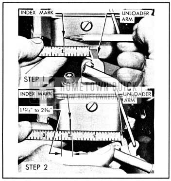
- While holding throttle valve fully closed, place a scale against choke unloader arm of throttle lever and make an index mark on float bowl at the one inch division on scale. See figure 10-30, step 1.
1950 Buick Checking Carter Accelerator Vacuum Switch Timing
Cleaning and Timing 1950 Buick Vacuum Switch
Switch timing may be changed without removing carburetor from engine; however, if switch is dirty the carburetor should be removed so that switch passages can be properly cleaned.
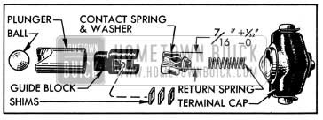
- Disconnect wires from terminals. Hold down on switch terminal cap while removing hold down clip. Remove terminal cap and return spring, then lift out switch guide block with contact spring and shims. Do not lose timing shims and the spring washer on contact spring. See figure 10-31.
1950 Buick Carter Accelerator Vacuum Switch Parts
1950 Buick Carter Accelerator Vacuum Switch Correctly Assembled
If the plunger is installed with groove down, as shown in figure 10-33, the ball will be prevented from rising into the ball passage when the engine starts.
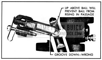
1950 Buick Carter Accelerator Vacuum Switch Incorrectly Assembled
As a result, the switch will close each time the throttle is opened, causing gear clash at low speeds when the generator is not producing sufficient voltage to open the solenoid relay. If generator should be inoperative, gear clashing would occur at all speeds.
10-33 1950 BUICK ACCELERATOR VACUUM SWITCH -ON STROMBERG CARBURETOR
Description and Operation
The accelerator vacuum switch used on Stromberg carburetors is mounted on the throttle body of the carburetor by two screws. A gasket placed between the switch housing and the throttle body seals against loss of vacuum.
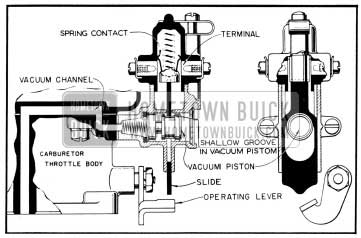
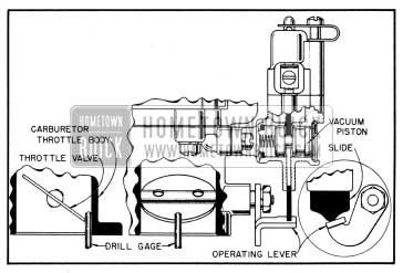
The switch housing is provided with a horizontal cylinder barrel to which vacuum from the engine manifold is applied at one end by means of cored and drilled passages in the carburetor bodies. This end of the barrel is provided with a washer which forms a seal to prevent leaks when a piston opposed by a light spring is drawn against it by vacuum. The opposite end of the barrel is vented to outside air through a fine mesh screen which is held in place by a screen clip. A flat slide, actuated by an operating lever on the throttle shaft, moves in a confined slot in the housing and in a plane perpendicular to the axis of the cylinder barrel. This slide engages a cylindrical bakelite contact guide, the upward movement of which is opposed by a heavy contact guide spring. The contact guide carries a thin U-shaped spring contact which moves up and down within a bakelite terminal cap to engage stationary contacts for opening and closing the cranking motor control circuit. The terminal cap is held in place by a cap screw and cap clip. See figure 10-34.
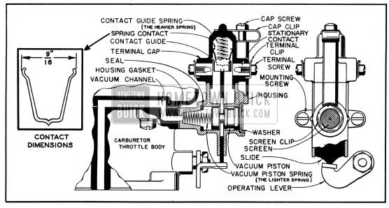
1950 Buick Stromberg Accelerator Vacuum Switch-Engine Not Running
Figure 10-34 shows the accelerator vacuum switch with engine not running. The throttle is closed and the switch operating lever holds the slide in the upper position, thereby holding the U-shaped spring contact away from the stationary contacts in the terminal cap.
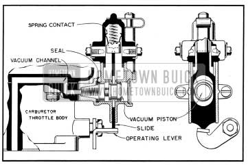
Pressing down on the accelerator pedal causes the operating lever to move away from the slide. This allows the contact guide spring to move the slide and U-shaped spring contact down to a position to bridge the stationary contacts in the terminal cap, thus closing the circuit. The slide moves into the deeper of the two grooves in the vacuum piston which has been positioned against the screen by the vacuum piston spring. See figure 10-35.
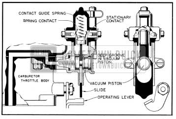
1950 Buick Stromberg Accelerator Vacuum Switch-Cranking Position
When the engine starts and the throttle is allowed to close, the slide and U-shaped spring contact is moved upward by the switch operating lever, opening the circuit. With the slide in the up position, manifold vacuum pulls the vacuum piston inward until it seats against the seal. This aligns the shallow groove in piston with the slide. See figure 10-36.
1950 Buick Stromberg Accelerator Vacuum Switch-Engine Running at Closed Throttle
When the throttle is opened beyond the idle range, the operating lever moves away from the slide which is then forced downward by the contact guide spring until it strikes the shallow groove in the vacuum piston. This acts as a stop and prevents the switch contacts from engaging while engine is running. It also holds the piston in the inner position when engine load conditions cause the vacuum to become too low to perform this function. See figure 10-37.
1950 Buick Stromberg Accelerator Vacuum Switch-Engine Running at Part or Open Throttle
It is very important that the switch contact is made at a specific throttle opening, to assure proper starting conditions. If the switch makes contact too early the throttle will not be opened sufficiently to give a good start. If the switch makes contact too late the throttle will be opened too far, which may cause gear clash as well as hard starting due to unloading of carburetor choke by the throttle mechanism. See subparagraph b, below.
Checking Switch Timing with Carburetor Installed on Engine
CAUTION: Before checking timing be sure that transmission is in neutral and apply parking brake.
- Set engine hot idle speed at 450 RPM. On Dynaflow car, make certain that throttle linkage and dash pot are correctly adjusted (par. 3-8).
- With engine not running, insert No. 65 drill or wire (small size paper clip) through center of screen to operate vacuum piston. DO NOT REMOVE SCREEN. See figure 10-38.
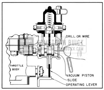
1950 Buick Pushing Vacuum Piston to Inner Position
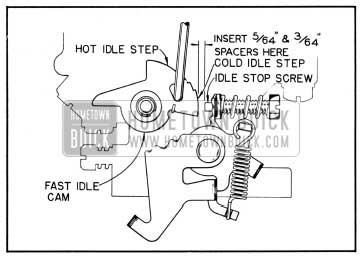
1950 Buick Spacer Between Idle Stop Screw and Fast Idle Cam
NOTE: A test light with a battery may be used in series with switch instead of turning on ignition.
- Still holding throttle open, place 3/64″ spacer between idle stop screw and fast idle cam while holding fast idle cam in extreme cold idle position. Close throttle so that spacer will hold cam in this position (fig. 10-39) and again open throttle with ignition on. Engine should crank.
- If the 5/64″ spacer causes the engine to crank, bend tang on operating lever downward. If the 3/64″ spacer does not cause engine to crank, bend tang on lever upward. In making either adjustment bend tang on operating lever only a slight amount each time until, ‘by rechecking with the above procedure, the specified spacing is obtained.
Setting Switch Timing with Carburetor Removed from Engine
If the carburetor has been removed from the engine an approximate switch timing setting may be made as follows:
- On Series 40-50, place a No. 43 drill between throttle valve and carburetor barrel. On Series 70, use a No. 41 drill. Close throttle valve to hold drill in position.
- Bend tang on switch operating lever until it just touches switch slide. See figure 10-40.
1950 Buick Setting Switch Timing with Carburetor Removed
Cleaning and Lubricating Switch
The accelerator vacuum switch may be removed for cleaning or replacement of parts without removing the carburetor. Disconnect wires and remove two screws which attach switch to the throttle body of carburetor.
The switch may be readily disassembled by referring to figure 10-34. Wash all metal parts in Bendix Metalclene, or equivalent, and wipe dry. Do not soak bakelite parts in cleaning solution, but wipe with a clean cloth.
Lubrication of switch contacts is unnecessary unless parts have been cleaned or replaced, in which case the inside surface of the terminal cap should be given a light coating of Beacon M-285 lubricant which is available in small tubes at authorized Stromberg Carburetor Service Stations. If this lubricant is not available petroleum jelly may be used. Lubricant should be applied sparingly by working into a clean cloth and lightly swabbing the inside surface of terminal cap.
CAUTION: Never use ordinary lubricants, as poor switch contact will be obtained in cold weather. Never apply lubricant to slide or piston.
When switch is reassembled observe the following points:
- Make certain that the contact guide spring and the vacuum piston spring are installed in their proper positions. The contact guide spring may be identified as the heavier of the two springs. See figure 10-34.
- Make certain that piston is installed with the end having the deep groove and tapered counterbore nearest the seal.
- Use care in handling the U-shaped contact spring to avoid altering the dimension of the open end. The open end measures % 6″ from outside to outside of the curved ends of spring. See figure 10-34.
- Make certain that the narrow projection on top of slide is properly entered in the slot in bottom of contact guide.
When switch is reinstalled on carburetor use a new gasket to insure a vacuum-tight seal. Check and set switch timing as described in subparagraph b, above.
10-34 1950 BUICK NEUTRAL SAFETY SWITCH – DYNAFLOW DRIVE CARS
Dynaflow Drive cars are provided with a neutral safety switch which prevents operation of the 1950 Buick cranking motor except when the transmission is in the Neutral (N) or Park (P) positions. This switch is a safety feature installed for the purpose of preventing car motion when starting the engine.
The neutral safety switch is connected in series with the 1950 Buick cranking motor control circuit, in the line between the ignition switch and the accelerator vacuum switch. It is mounted at the lower end of the steering gear column jacket and is operated by the lever at lower end of the transmission control shaft.
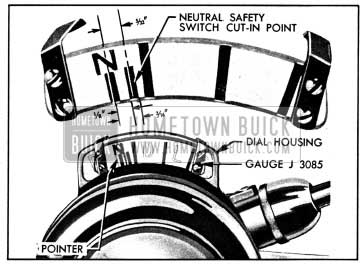
When properly adjusted, the neutral safety switch remains closed, to permit cranking the engine, until the center of speed ratio dial pointer is moved approximately 5/32″ out of neutral (N) toward driving (D) position.
If the switch opens when center of pointer is less than 1/8″ from neutral, the 1950 Buick cranking motor control circuit may not be completed when transmission control lever is in neutral. If the switch remains closed when center of pointer is more than 3/16″ out of neutral, the 1950 Buick cranking motor might be operated before the transmission is completely out of the driving (D) range.
Checking 1950 Buick Neutral Safety Switch Timing Adjustment with Gauge
- Check manual control linkage and adjust if necessary (par. 4-17) .
- Ground primary terminal of distributor with jumper wire so that engine can be cranked without firing.
- Firmly engage “step-on” parking brake and place transmission control lever in neutral (N) position, making sure that detent is firmly engaged.
- Install Gauge J 3085 on speed ratio dial housing so that the short line under “N” is centered on the dial pointer. See figure 10-41.
1950 Buick Gauge J 3085 Set for Timing the Neutral Safety Switch
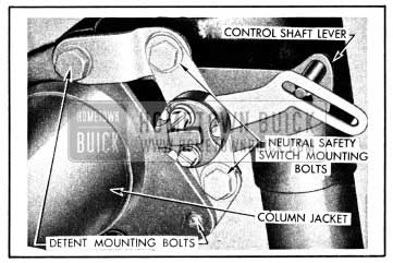
1950 Buick Neutral Safety Switch Mounting
Checking 1950 Buick Neutral Safety Switch Timing Adjustment Without Gauge
The neutral safety switch timing can be most easily checked and adjusted by use of Gauge J 3085 as described above. If this gauge is not available, the following method may be used.
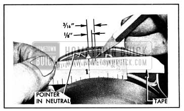
- Place a narrow strip of masking tape on speed ratio dial so that upper end of dial pointer is visible.
- Make two marks on masking tape at 1/8″ and 3/16″ from center of pointer. See figure 10-43.
1950 Buick Marking Tape for Checking Switch Timing
These marks give the same cut-in limits as provided by Gauge J 3085.
- Check and adjust switch timing in the same manner as with Gauge J 3085 (subpar. b).
10-35 1950 BUICK CRANKING MOTOR ASSEMBLY
The 1950 Buick cranking motor assembly consists of a motor, drive assembly, shift lever, solenoid switch and relay. See figure 10-44. It is mounted on the flywheel upper housing on the right side of engine.
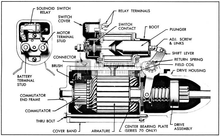
1950 Buick Cranking Motor, Sectional View-Series 70
1950 Buick Cranking Motor
The motor used on Series 40-50 is of the induced pole type having four brushes and four poles but only two field coils. The motor used on Series 70 is a four pole motor having four brushes and four field coils. Both motors are series-wound.
The armature shaft is supported at both ends in graphite bronze bushings pressed into the commutator end frame and the drive housing. In the Series 70 motor, the shaft is also supported by a graphite bronze bushed center bearing plate which is mounted on the inner end of the drive housing. None of these bearings require lubrication. See figure 10-44.
The four brushes are supported by brush holders mounted on the commutator end frame. Two opposing brushes are grounded to the frame and the other two opposing brushes are connected to the field coils. The field coils are held in place by the pole shoes which are attached to the field frame by large screws. The field coils are connected to an insulated terminal stud on the field frame, through which current is supplied to the motor.
1950 Buick Cranking Motor Drive Assembly and Shift Lever
The drive assembly is mounted on the motor armature shaft and keyed to it by splines so that it can be moved endwise on the shaft by the solenoid operated shift lever. It transmits cranking torque to the flywheel ring gear, but allows the drive pinion to rotate freely with reference to the armature shaft when the engine begins to operate, thus preventing the armature from being driven at excessive speed by the engine.
The drive assembly consists of a pinion-and collar, overrunning clutch, spring, and shift collar. The overrunning clutch consists of a shell and sleeve assembly, which is internally splined to the armature shaft. The pinion collar fits within the clutch shell. Four tapered notches cut in the clutch shell house four hardened steel rolls in position so that they can bear against the pinion collar. A spring and plunger presses each roll toward the small end of the notches and into contact with the pinion collar. See figure 10-45.
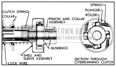
1950 Buick Cranking Motor Drive Assembly, Sectional Views
When the clutch shell is rotated by the armature shaft, the rolls jam between the shell and pinion collar and force the pinion to rotate with the shell. When the pinion is rotated by the flywheel ring gear, after the engine starts, the rolls are rotated out of the small end of the notches so that the pinion collar and clutch shell are no longer locked together, consequently the high speed of the pinion is not transmitted to the armature shaft.
The drive assembly pinion is moved into engagement with flywheel ring gear by action of the solenoid upon the shift lever, which engages the shift collar of drive assembly. The shift collar moves the drive assembly by pushing on the clutch spring, which serves as a cushion in case the pinion and gear teeth butt instead of meshing. The drive pinion is pulled out of engagement, after engine starts, by action of the shift lever return spring. The shift lever is connected to the solenoid switch plunger by a link and adjusting screw. See figure 10-44.
The drive pinion on all series has 9 teeth. The flywheel ring gear on Series .1,.0-50 has 146 teeth, providing a gear ratio of 16.22 to 1. The flywheel ring gear on Series 70 has 156 teeth, providing a gear ratio of 17.33 to 1.
1950 Buick Solenoid Switch and Relay
The solenoid switch not only closes the circuit between the battery and the 1950 Buick cranking motor to produce cranking action, but it also operates the shift lever to move the drive pinion into engagement with the flywheel ring gear.
The solenoid section of the switch has a plunger and two windings, the “pull-in” winding and the “hold-in” winding. Together, they provide sufficient magnetic attraction to pull the solenoid plunger into the solenoid. The plunger actuates the shift lever and drive assembly and it also closes the solenoid switch contacts by pressing against a push rod upon which a contact disk is mounted between two coil springs. One spring serves as a cushion to insure firm contact of the disk with two stationary contacts. The other spring pushes the disk away from the stationary contacts to break the circuit when the solenoid is demagnetized after the engine starts. One stationary contact is connected to the battery positive cable and the other is connected to the motor windings through a connector or bus bar. See figure 10-44.
The solenoid switch relay is an electrical switch which closes the circuit between the battery and the solenoid windings when cranking action is desired, and opens the circuit when the engine starts running. The relay has one winding surrounding a core which, when magnetized by current flowing through the winding, attracts a flat steel armature. The armature has a contact point which makes contact with a stationary point to close the circuit.
Operation of the solenoid switch and relay, as well as the entire 1950 Buick cranking system, is described in paragraph 10-31.
As a general rule, the 1950 Buick cranking motor should be tested and inspected every 5000 miles to determine its condition; however, the type of service in which some cranking motors are used may make more frequent inspection advisable. Frequent starts, as in city operation, excessively long cranking periods caused by hard-starting engine conditions, excessively dirty or moist operating conditions, all will make more frequent inspection advisable.
1950 Buick cranking motor action is indicative, to some extent, of the cranking motor condition. A 1950 Buick cranking motor that responds readily and cranks the engine at normal speed when the
control circuit is closed is usually in good condition. The following inspection should be made, however, to insure continued satisfactory operation.
- Remove commutator cover band and inspect it for thrown solder which results if 1950 Buick cranking motor is subjected to excessively long cranking periods, causing it to overheat. Since thrown solder results in loose or broken connections between armature windings and commutator riser bars, which usually causes burned commutator bars, the motor must be removed for repairs (par. 10-41).
- Inspect commutator; if it is rough, out of round, or has high mica between the bars it will require turning down and undercutting of the mica. The motor must be removed for this work.
- Check condition of brushes; make sure they are not binding and that they are resting on the commutator with sufficient tension to give good, firm contact. Brush leads and screws must be tight. If the brushes are worn down to one-half their original length, compared with new brushes, the motor must be removed for installation of new brushes.
- If commutator and brushes are in good condition but dirty, they may cleaned without removal of motor. Clean off any grease with a cloth soaked with carbon tetrachloride or other non-inflammable solvent. While motor is operating, quickly polish commutator with a brush seating stone or with a strip of 2/0 sandpaper placed over a wooden block having a smooth square end. Do not use emery cloth. To operate 1950 Buick cranking motor, turn ignition switch off and connect a jumper wire between battery terminal of solenoid switch and the terminal of solenoid relay to which the wire with black parallel tracer is connected. CAUTION: Do not operate 1950 Buick cranking motor more than 30 seconds at a time without pausing to allow motor to cool for at least two minutes; otherwise, overheating and damage to motor may result. After cleaning commutator, blow out all dust from 1950 Buick cranking motor.
- Check motor and solenoid switch attaching bolts to make sure these units are solidly mounted. Inspect and manually check all wiring connections at solenoid switch, solenoid relay, generator regulator, generator, accelerator vacuum switch, ignition switch, No. 1 terminal of headlamp lighting switch, charge indicator, and neutral safety switch (Dynaflow Drive cars only). Make sure that all these connections in the cranking motor and control circuits are clean and tight. It is advisable to test the cranking circuit to make certain that excessive resistance does not exist. See paragraph 10-37.
10-37 VOLTAGE TEST OF 1950 BUICK CRANKING MOTOR AND 1950 BUICK SOLENOID SWITCH
The voltage across the 1950 Buick cranking motor and switch while cranking the engine gives a good indication of any excessive resistance. NOTE: Engine must be at normal operating temperature when test is made.
- Inspect battery and cables (par. 10-17) to make certain that battery has ample capacity for cranking and ignition.
- Connect jumper wire to primary terminal of distributor and to ground on engine, so that engine can be cranked without firing.
- Connect voltmeter positive ( +) lead to the motor terminal on solenoid switch; connect voltmeter negative (-) lead to ground on engine. See figure 10-46.
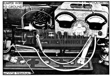
1950 Buick Cranking Voltage Test Connections
CAUTION: Do not operate 1950 Buick cranking motor more than 30 seconds at a time without pausing to allow motor to cool for at least two minutes; otherwise, over heating and damage to motor may result.
- If 1950 Buick cranking motor turns engine at low rate of speed with voltmeter reading less than 4.5 volts, test solenoid switch contacts as follows.
- Connect voltmeter negative (-) lead to the motor terminal of solenoid switch, and connect positive (+) lead to battery terminal of switch. Turn voltmeter switch to low voltage scale. See figure 10-47.
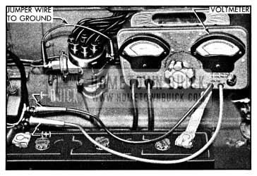
1950 Buick Solenoid Switch Contact Test Connections
10-38 TEST AND ADJUSTMENT OF 1950 BUICK SOLENOID SWITCH RELAY
When the solenoid switch relay is operating properly, the contact points will close at 1.2 to 1.8 volts, and will open at not less than .6 volts, when tested with relay cold (at room temperature). The relay must cut in at this low voltage so that it will operate during cold weather with a low battery.
The solenoid switch relay should not be tampered with unless the proper test equipment is available. Test equipment consists of an accurate low reading voltmeter and a variable rheostat of at least 10 ohm having a capacity for 2 amperes.
Testing 1950 Buick Solenoid Switch Relay Cut-in and Cut-out Voltages
Solenoid switch relay cut-in and cut-out voltages may be determined with 1950 Buick cranking motor installed and without removing switch cover as follows:
- Make sure that ignition switch is turned off.
- Set rheostat to provide full resistance. Connect one lead of rheostat to battery terminal on solenoid switch, and connect other lead to terminal on solenoid switch relay which has white wire with black parallel tracers connected to it. This wire is connected to the accelerator vacuum switch. See figure 10-48.
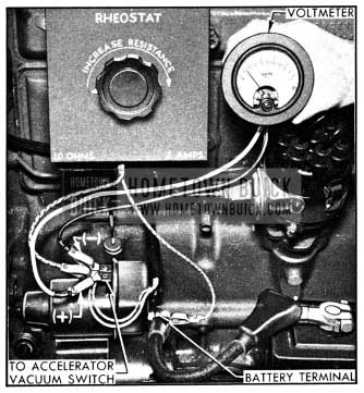
1950 Buick Connections for Testing Cut-in and Cut-out Voltages of Solenoid Switch Relay
1950 Buick Solenoid Switch Relay Adjustments
When the solenoid switch relay does not operate within the voltage limits specified in subparagraph a above, five checks and adjustments must be made in the following order: Air gap, contact point opening, closing voltage, sealing voltage and opening voltage. This work cannot be properly done with 1950 Buick cranking motor installed on engine.
- Remove 1950 Buick cranking motor from engine and remove switch cover.
- Push relay armature down until contact points just touch, then check air gap between armature and end of core, using .015″ feeler gauge. Air gap should be not less than .015″. Adjust gap to .015″, if necessary, by bending the lower point support. See figure 10-49.
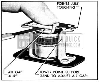
1950 Buick Relay Air Gap Adjustment
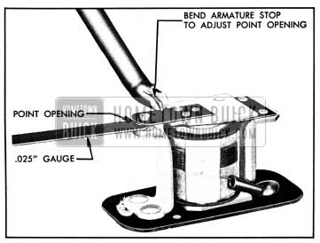
1950 Buick Relay Contact Point Adjustments
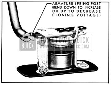
1950 Buick Relay Closing Voltage Adjustment
10-39 1950 BUICK SOLENOID SWITCH TEST AND REPAIRS-CRANKING MOTOR ON BENCH
Testing Solenoid Switch Windings
When the 1950 Buick cranking motor is removed from engine, the solenoid switch windings can be tested with switch either on or off the 1950 Buick cranking motor, if the required test instruments are available. Two tests must be made to determine: (1) Current draw of both windings in parallel; (2) Current draw of hold-in winding alone.
- Remove switch-to-motor connector, and remove switch cover and gasket.
- Connect 6-volt battery, a variable resistance, and an ammeter of 75 amperes capacity in series with base of solenoid and the terminal on relay to which solenoid windings are soldered. Connect voltmeter between solenoid base and the solenoid winding leads at relay terminal. Ground the switch motor terminal to solenoid base with a jumper wire.
- Slowly adjust resistance until voltmeter reads 5 volts and note current draw on ammeter. Current draw of both windings in parallel should be 65 to 71 amperes at 5 volts. CAUTION: Do not close the solenoid relay contact points when making this test since this would cause a direct short when the solenoid switch operates.
- Remove jumper wire and readjust resistance until voltmeter reads 5 volts. The current draw of the hold-in winding alone should be 12 to 14 amperes at 5 volts.
- If the solenoid windings do not test within the specifications given, the solenoid switch assembly requires replacement.
Replacement of Parts
The solenoid switch may be disassembled by removal of parts as shown from right to left in figure 10-52.
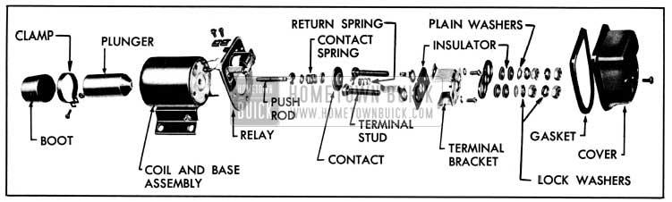
1950 Buick Solenoid Switch Disassembled
For replacement of the relay assembly it is necessary to unsolder the solenoid winding leads. When resoldering leads use only rosin flux-never use acid flux when soldering electrical connections.
It is not necessary to unsolder the solenoid winding leads in order to replace the switch contact disk or terminal studs.
When assembling switch, note that two fiber washers, a plain washer, and a lock washer go on each terminal stud before installing the first nut.
Installing 1950 Buick Solenoid Switch and Adjusting Drive Pinion Travel
Whenever the solenoid switch is removed and reinstalled on 1950 Buick cranking motor it is necessary to adjust the drive pinion travel so that there will be 3/16″ clearance between the end of pinion and the drive housing when pinion is in cranking position.
- Remove the connector between solenoid switch and cranking motor terminals so that motor will not operate.
- Remove solenoid switch cover and connect around relay points with a jumper wire.
- Connect a 6-volt battery to solenoid switch terminals, and push solenoid plunger into solenoid by hand. Once in, battery current will hold it in place so that the drive pinion clearance can be checked and adjusted.
- Press finger lightly against outer side of drive assembly shell to take out all lash in shift linkage, then measure clearance between end of pinion and machined surface on drive housing. Clearance should be 3/16″. See figure 10-53.
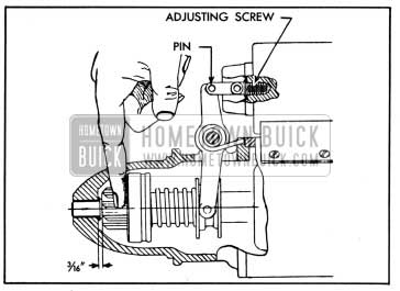
1950 Buick Checking Pinion Travel
10-40 BENCH TEST OF 1950 BUICK CRANKING MOTOR
To obtain full performance data on a 1950 Buick cranking motor, or to determine the cause of abnormal operation, the motor should be removed from the engine and be submitted to a no-load and a torque test.
1950 Buick Cranking Motor Tests and Equipment Required
In the no-load test, the 1950 Buick cranking motor is connected in series with a 6-volt battery and an ammeter capable of reading several hundred amperes. A voltmeter is connected between the insulated motor terminal and ground on the frame at a point free of grease and paint. A speed indicator should also be used to measure the armature revolutions per minute.
The torque test requires equipment such as shown in figure 10-54.
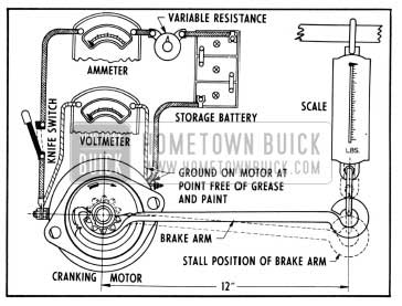
1950 Buick Diagrammatic Layout for Cranking Motor Torque Test
The 1950 Buick cranking motor is securely mounted and the brake arm hooked to the drive pinion. With a one-foot brake arm as shown, the torque w.ill be indicated directly on the scale in pounds feet when the specified voltage is applied to the motor. Specified voltage is applied through the use of a high-current carrying variable resistance.
An armature growler and a test lamp with pointed prods on the leads are also required for checking internal condition of armature and the field windings.
Interpreting Results of Tests
Test specifications are given under Electrical Specifications (par. 10-3). The specifications are given at low voltages so that torque and ammeter readings obtained will be within the range of testing equipment available in the field.
- Rated torque, current draw and no-load speed indicates normal condition of 1950 Buick cranking motor.
- Low free speed and high current draw with low developed torque may result from:
- Tight, dirty, or worn bearings, bent armature shaft or loose field pole screws which would allow the armature to drag.
- Shorted armature. Check armature further on growler (par. 10-28, c).
- A grounded armature or field. Check by raising the grounded brushes and insulating them from the commutator with cardboard, and then checking with a test lamp between the insulated terminal and the frame. If lamp lights, raise other brushes from commutator and check fields and commutator separately to determine whether it is the fields or armature that is grounded.
- Failure to operate with high current draw may result from:
- A direct ground in the terminal or fields.
- Frozen shaft bearings which prevent the armature from turning.
- Failure to operate with no current draw may result from:
- Open field circuit. Inspect internal connections and trace circuit with test lamp.
- Open armature coils. Inspect the commutator for badly burned bars.
- Broken or weakened brush springs, worn brushes, high mica on the commutator, or other causes which would prevent good contact . between the brushes and commutator. Any of these conditions will cause burned commutator bars.
- Low no-load speed with low torque and low current draw indicates:
- An open field winding. Raise and insulate ungrounded brushes from commutator and check field with test lamp.
- High internal resistance due to poor . connections, defective leads, dirty commutator. and causes listed under item 4 (c). Running free speed, an open armature will show excessive arcing at the commutator bar which is open.
- High free speed with low developed torque and high current draw indicates shorted fields. There is no easy way to detect shorted fields, since the field resistance is already low. If shorted fields are suspected, replace the fields and check for improvement in performance.
10-41 1950 BUICK CRANKING MOTOR REPAIRS ON BENCH
Disassembly, Cleaning, and Inspection of 1950 Buick Cranking Motor
When it is necessary to disassemble 1950 Buick cranking motor for any reason, make a complete clean up and inspection to make sure all parts are in satisfactory condition. See figure 10-55 for identification of parts.
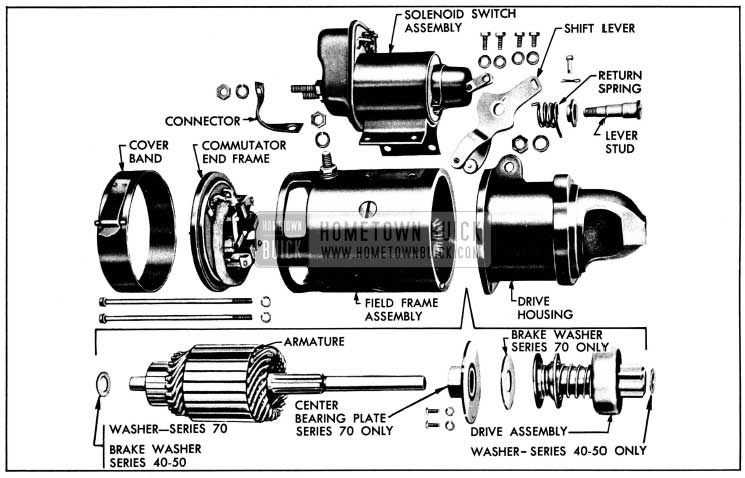
1950 Buick Cranking Motor Disassembled
- Disconnect plunger from shift lever by removing adjusting screw link pin. Remove solenoid switch.
- Remove commutator cover band and disconnect brush leads from the field leads.
- Unscrew the through bolts and separate the commutator end frame, field frame, and drive housing.
- On Series 70 cranking motor, remove the center bearing plate and thrust washer from drive housing.
- Remove shift lever and spring, then remove drive assembly from drive housing.
- If field coils are to be removed from field frame, a pole shoe spreader and pole shoe screwdriver should be used to avoid distortion of frame. See figure 10-56.
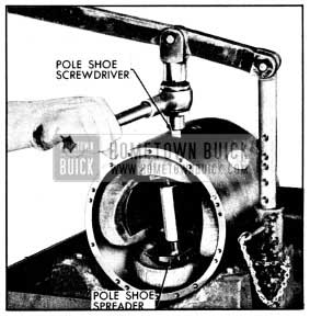
1950 Buick Using Pole Shoe Spreader and Screwdriver
Assembly of 1950 Buick Cranking Motor
Assemble 1950 Buick cranking motor by reversing disassembly procedure. If field coils were removed, use pole shoe spreader and pole shoe screwdriver to install them, to avoid distorting field frame and to insure proper tightening of pole shoe screws. See figure 10-56.
Before installation of solenoid switch check the shift lever spring for proper tension. A weak spring may cause sluggish disengagement of drive clutch pinion in cold weather, particularly if the shaft is gummed up. With spring scale connected to hole in upper end of shift lever, the pull at start of travel should be 9 to 12 pounds and at end of travel should be 28 to 35 pounds.
When solenoid switch plunger is connected to shift lever, adjust drive pinion travel to provide 3/16″ clearance in cranking position as described in paragraph 10-39 (c).
If new brushes were installed, or old brushes were removed from holders, loosen brush attaching screws to allow brushes to seat squarely against commutator, then firmly tighten screws. Attach spring scale at each brush and check the pull required to just lift brush off commutator. Brush spring tension should be 24 to 28 ounces. If spring tension is excessive, pull brush holder out to limit of travel several times to give a slight bend to spring. If spring tension is too light, replace brush spring. Make sure that brush holders do not bind on the support pins.
Leave A Comment
You must be logged in to post a comment.