SECTION 3-F 1950 BUICK STROMBERG CARBURETOR AND AUTOMATIC CHOKE
3-25 1950 BUICK STROMBERG CARBURETOR IDENTIFICATION NUMBERS
Stromberg carburetors used on 1950 engines have the following model and code numbers:
The model designation indicates the basic design of the unit. The code number which is stamped on the float bowl cover (air horn) directly above the fuel level sight plug, furnishes the key to the size, calibrations, and other alterations required for the particular year and series engine for which the unit is specified.
Carburetors having different code numbers are not interchangeable even though the model designations are identical. The variations between carburetors having different code numbers may not be apparent on inspection, but they have a very important bearing on the performance of an engine.
When ordering or using replacement parts for a 1950 Buick Stromberg carburetor always make certain that they are specified for the carburetor model and code number, as well as for the car model and series.
3-26 DESCRIPTION AND OPERATION OF 1950 BUICK STROMBERG CARBURETOR
General Description
The AAV Stromberg carburetor is a dual barrel down-draft type. See figure 3-46.
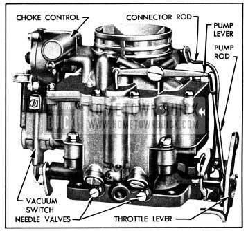
1950 Buick Stromberg Carburetor Assembly
It contains a float system, idle (low speed) system, main metering (high speed) system, power system, accelerating system, and automatic choke. An accelerator vacuum switch, which is part of the cranking motor control circuit, is incorporated in the carburetor assembly.
Air is supplied to both barrels of carburetor through the air horn which has one inlet and contains the choke valve. Fuel is supplied to both barrels from one float chamber. The float chamber encircles both barrels and contains a dual type float and lever assembly which actuates one float needle valve. The accelerating pump discharge nozzle in each barrel is supplied with fuel from one pump located in the float chamber. The power system for both barrels is controlled by one vacuum power piston.
Except as noted above, each barrel forms a complete carburetor system. Each barrel contains an idle system with adjustable needle valve, a main metering system, accelerating pump discharge nozzle, primary and auxiliary venturi tubes, and a throttle valve. The throttle valves of both barrels are mounted in line on one stem. The dual construction provides the advantages of two carburetors in one compact unit. The dual carburetor and dual intake manifold provides more uniform distribution of fuel to all cylinders than would be possible with one single barrel carburetor.
Operation of each system of the AAV Stromberg carburetor is described in the following subparagraphs. The automatic choke is described in paragraph 3-27, which follows. The accelerator vacuum switch is described in paragraph 10-33.
Operation of Stromberg Float System
Fuel enters the carburetor at the gasoline connection and flows through the strainer and needle valve seat into the float chamber. When the fuel reaches the prescribed level in float chamber, the dual float presses the needle valve against its seat to shut off the flow of fuel. Thereafter, the fuel is maintained at the prescribed level by opening and closing of the needle valve as required. The float lever is hinged on a fulcrum pin and connected to the needle valve by a clip. See figure 3-47.
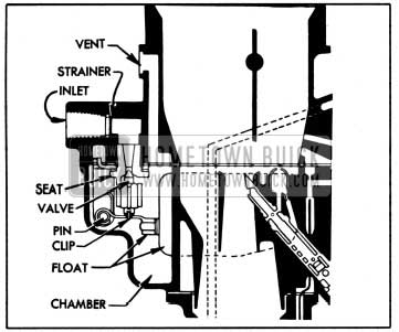
1950 Buick Float System-Stromberg Carburetor
The float chamber is vented externally through a port in air horn to allow fuel to be smoothly withdrawn through the various systems.
Operation of Stromberg Idle (Low Speed) System
Fuel is delivered to the engine through the idle system at closed throttle and light load speeds up to approximately 20 MPH. The idle system also partially controls fuel supply for light load speeds up to approximately 30 MPH.
The operation of the idle system in each barrel of the carburetor is identical. Fuel flows from the float chamber through main metering jet and upward through the idle tube which meters the fuel. From the idle tube it flows through a connecting channel where air from the idle air bleeder is mixed with it so that a mixture of air and fuel passes down the idle channel to the idle discharge holes. Additional air is drawn into the fuel air mixture in the idle channel through the secondary air bleeder. See figure 3-48.
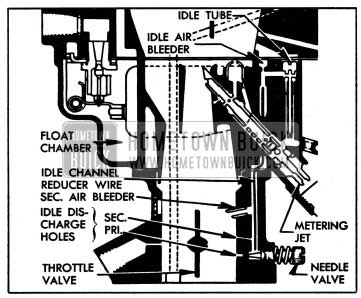
1950 Buick Idle System-Stromberg Carburetor
On idle or closed throttle operation, the fuel air mixture is drawn only from the lower or primary idle discharge hole due to high suction at this point. As throttle valve is opened, suction is also placed on the upper or secondary idle discharge hole to feed additional fuel. Fuel supplied through the idle discharge holes begins to diminish when the throttle valve is opened to the point where the main metering system begins to supply fuel, as described below, until a throttle position is reached where the idle system ceases to function.
The idle needle valve controls the quantity of fuel that is supplied through the primary idle discharge hole, thereby affecting the final fuel-air ratio supplied to the engine while the idle system is in operation.
Operation of Stromberg Main Metering System
The main metering system controls the flow of fuel during the intermediate or part-throttle operation, starting at approximately 20 MPH and continuing up to approximately 75 MPH.
The operation of the main metering system in each barrel of the carburetor is identical. Air entering the barrel through the air horn passes through the primary and auxiliary venturi tubes which increase the velocity of the air and. create a suction on the main discharge jet. This causes fuel to flow from the float chamber through the main metering jet into the main discharge jet. Air is drawn in through the high speed bleeder so that a mixture of fuel and air is discharged from the main discharge jet into the air stream passing through the auxiliary venturi in the barrel of the carburetor. See figure 3-49.
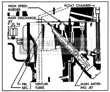
1950 Buick Main Metering System-Stromberg Carburetor
The main discharge jet is designed so that if any vapor bubbles are formed in the hot gasoline, the vapors will follow the outside channel around the main discharge jet instead of passing through the jet tube. These vapor bubbles escape through the dome-shaped high speed bleeder and thereby reduce percolating troubles.
Operation of Stromberg Power System
For maximum power or high speed operation above approximately 75 MPH a richer mixture is required than that necessary for normal throttle opening. The richer mixture is supplied through the main metering systems of both barrels of carburetor by means of the power system.
The power piston cylinder is connected by a channel to the intake manifold. At part throttle position the manifold vacuum is sufficient to hold the power piston in its “up” position against the tension of the piston spring. When the throttle valve is opened to a point where additional fuel is required for satisfactory operation, the manifold vacuum decreases sufficiently so that the piston spring moves the power piston down to open the power by-pass jet. Opening of the by-pass jet allows additional fuel to enter the main discharge jets through a by-pass channel without passing through the restricted main metering jet. See figure 3-50.
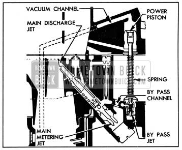
1950 Buick Power System-Stromberg Carburetor
Operation of Stromberg Accelerating System
For smooth and rapid acceleration it is necessary to supply an extra quantity of fuel momentarily when the throttle is suddenly opened. This is accomplished by operation of the accelerating pump piston which is directly connected to the throttle valve lever by means of a rod and pump lever. See figure 3-51.
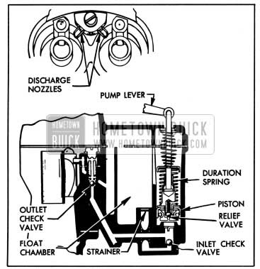
1950 Buick Accelerating System-Stromberg Carburetor
When the throttle is closed, the pump piston moves up and draws a supply of fuel from the float chamber through the inlet check valve into the pump cylinder. When the throttle valve is opened, the piston on its downward stroke exerts pressure on the fuel which closes the inlet check valve, opens the outlet check valve, and discharges a metered quantity of fuel through the pump discharge nozzles in each barrel of carburetor. This occurs only momentarily during the accelerating period. The pump duration spring provides a follow-up action so that the fuel discharge carries out over a brief period of time. The relief valve in the pump piston prevents excessive build-up of pressure in the accelerating systems when the throttle is suddenly snapped open.
When the desired speed is reached and the throttle is held in fixed position, the pressure on the fuel in the pump cylinder decreases sufficiently so that the outlet check valve closes and fuel ceases to discharge from the pump nozzles. With the throttle held in a fixed position the fuel flows only through the idle or main metering systems as previously described.
3-27 DESCRIPTION AND OPERATION OF STROMBERG AUTOMATIC CHOKE
General Description
The Stromberg automatic choke consists of a choke valve mounted on a stem or shaft in the carburetor air horn, a bi-metal thermostat and cover, a vacuum actuated piston located in a
choke housing attached to the air horn, a fast idle rod connecting the choke valve to a fast idle cam mounted on carburetor throttle body. An upper heat pipe connects the choke housing to a lower heat pipe in the exhaust manifold.
The choke valve is mounted off-center in the choke stem so that the force of air stream passing through the air horn tends to move valve to the open position. A short lever mounted on the choke stem in choke housing is engaged by the free outer end of the thermostat which, when cold, tends to close the choke valve. The piston, which is actuated by intake manifold vacuum, is connected by a link to the short lever on choke stem and tends to open the choke valve when the engine fires.
The lower heat pipe in the exhaust manifold heats the air which is drawn through it and the upper heat pipe into the choke housing. A small slot in the vacuum piston and a small hole in choke housing permit manifold vacuum to draw the air into the choke housing to heat the thermostat.
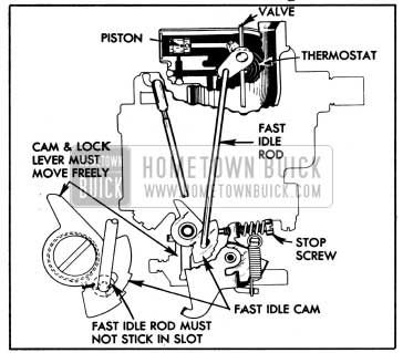
The fast idle cam is connected by the fast idle rod to a lever on the outer end of the choke stem so that it is rotated as the choke valve moves. In closed throttle position, the throttle stop screw bears against one edge of the fast idle cam which has a number of steps of different heights to give different amounts of throttle opening, depending on positions of the cam and choke valve.
Choke Operation-Cold Engine
When the engine becomes cold the choke thermostat also becomes cold and increases its spring tension sufficiently to close the choke valve. It is prevented from closing the valve, however, because the throttle stop screw holds the fast idle cam in the slow idle position; consequently, the choke valve is held partially open.
When the accelerator pedal is depressed to start the engine, the throttle stop screw is lifted clear of the fast idle cam and the thermostat then closes the choke valve. See figure 3-52.
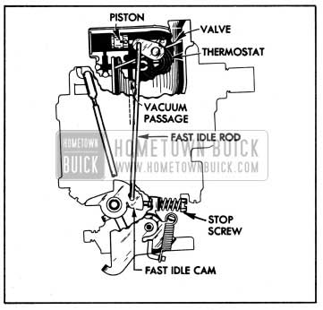
1950 Buick Stromberg Choke In Cold Starting Position
When the engine starts, intake manifold vacuum causes the piston to partially open the choke valve against the spring tension of thermostat, thereby admitting sufficient air to give a satisfactory running mixture.
When accelerator pedal is released after starting the engine, the throttle stop screw comes to rest against a step of fast idle cam which was rotated to the fast idle position by the closing of choke. This provides proper throttle opening to prevent stalling of the cold engine. See figure 3-52.
If the throttle is partially opened while the running engine is cold, the increased force of air flow against the off-set choke valve will open the valve against the spring tension of the thermostat. These opposing forces balance the choke valve at a position which provides the required choke action without causing loading or an excessively rich mixture. After starting, the vacuum piston does not help to open the choke valve.
Choke Operation-Warm-up Period
As the engine and exhaust manifold warm up, warm air is drawn through the heat pipes into the choke housing by manifold vacuum operating through the small slot in vacuum piston and hole in choke housing. This warms the thermostat, causing it to reduce its spring tension on choke valve in proportion to the increase in temperature.
When the throttle is opened and throttle stop screw is lifted from the fast idle cam, the choke valve then moves to a more open position and the fast idle cam is rotated to bring a lower step into position for the throttle stop screw. The engine will then run at a lower speed at closed throttle. See figure 3-53.
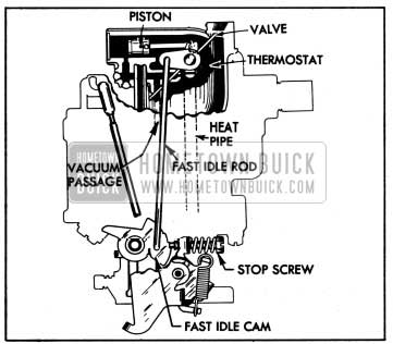
1950 Buick Stromberg Choke During Warm-up
Choke Operation-Hot Engine
When the engine reached normal operating temperature, the choke thermostat is heated to the point where it no longer exerts any spring tension on the choke valve. The choke valve is in the wide open position and the fast idle cam is in the slow idle position so that the throttle stop screw bears against the lowest step of fast idle cam at closed throttle. See figure 3-54.
1950 Buick Stromberg Choke in Hot Position
Choke Unloader Operation
If the engine becomes flooded for any reason, the choke valve can be partially opened by depressing accelerator pedal to the full extent of its travel. This causes a tongue or arm on the throttle lever to contact and rotate the fast idle cam, which forces the choke valve open. See figure 3-57.
1950 Buick Stromberg Choke Unloader Adjustment
3-28 ADJUSTMENT OF FAST IDLE CAM AND CHOKE UNLOADER
If the engine operates on fast idle too long after starting or else moves to slow idle too soon, or the choke unloader does not operate properly, adjust fast idle cam and choke unloader as follows:
- Remove air cleaner and silencer.
- Place a No. 26 drill (0.147″) between wall of air horn and the center of upper edge of choke valve, and hold valve firmly closed against the drill. See figure 3-55.
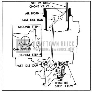
1950 Buick Stromberg Fast Idle Cam Adjustment
1950 Buick Stromberg Start Aid Lever Adjustment
3-29 DISASSEMBLY, CLEANING, INSPECTION OF 1950 BUICK STROMBERG CARBURETOR AND CHOKE
Removal of Carburetor
- Remove air cleaner and silencer.
- Disconnect throttle rod, accelerator vacuum switch wires, choke upper heat pipe, vacuum spark control pipe, and gasoline pipe.
- Remove gasoline filter from carburetor, then remove carburetor and gasket from manifold.
Disassembly of Carburetor
- Remove accelerator vacuum switch and gasket.
- Remove cotter pin and disconnect fast idle rod from choke stem lever.
- Disconnect pump rod from pump lever by pushing upward on spring housing and pulling rod outward. Remove pump lever fulcrum screw (left hand thread) and spring washer then disconnect pump lever from stem of accelerating pump piston.
- Remove screws and carefully lift air horn straight up from main body to avoid damaging the float, pump piston, and vacuum power piston which are attached to air horn. Remove pump piston. See figure 3-58.
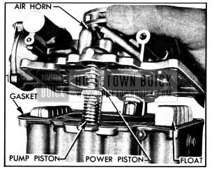
1950 Buick Removing Air Horn and Attached Parts
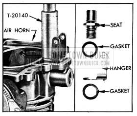
1950 Buick Removing Needle Valve Seat and Float Hanger
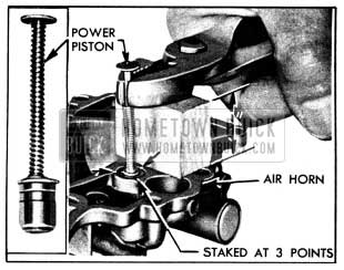
1950 Buick Removing Vacuum Power Piston
1950 Buick Stromberg Choke Control Parts
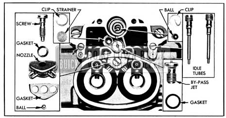
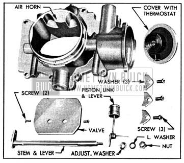
1950 Buick Parts in Main Carburetor Body
Handle idle tubes carefully to avoid damaging small end which contains metering orifice.
- Remove pump discharge nozzle screw, nozzle and gaskets. Place hand on top of main body and invert body to catch the check valve ball located in discharge channel. See figure 3-62.
- Remove pump check valve ball retainer clip, using long nosed pliers, then remove check valve ball. See figure 3-62.
- Remove attaching screws and lift main body from throttle body. Remove gasket and idle channel wires from throttle body.
- Remove main discharge jet plugs using Screw Driver T-19099, remove copper gaskets, then remove main metering jets using Jet Socket T-24924. See figure 3-63.
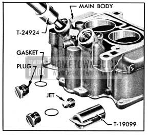
1950 Buick Removing Plug and Main Metering Jet
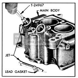
1950 Buick Removing Main Discharge Jet
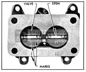
1950 Buick Identiflcation Marks on Throttle Valves
Cleaning Carburetor Parts
Regardless of the number of new parts that are used in rebuilding a carburetor, the job in the end will not be satisfactory unless all metal parts are thoroughly cleaned. Because of the nature of carburetor parts, with numerous small passages subject to fouling with tenacious carbon and gum deposits, ordinary cleaning processes are entirely inadequate. The correct procedure is to use a cleaning bath in which metal parts can be immersed and “soaked” for sufficient time after disassembly to thoroughly clean all surfaces and channels.
Bendix Metalclene has been developed especially for cleaning carburetors, and is recommended for this purpose. Regardless of the cleaning material used, however, be sure to thoroughly rinse the parts in kerosene, distillate, or white gasoline to remove all gummy deposits that have been softened by the cleaner.
If the passages in main body appear to be heavily fouled with carbon or gum it is advisable to remove the lead ball plugs so that the cleaning solvent can penetrate and wash through the channels. Lead ball plugs may be removed with Plug Remover T-25052, using care not to damage the plug seats in body. See figure 3-66, view A. Install new ball plugs after cleaning is completed, using Plug Set T-25053 to swage plug into its seat. See figure 3-66, View B.
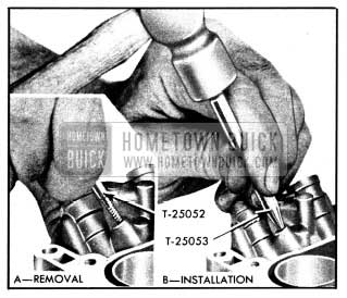
1950 Buick Removal and Installation of Ball Plugs
Inspection of Carburetor Parts
After cleaning, all parts should be carefully inspected for wear or damage as follows:
- Air Horn and Choke Parts. It is very necessary for the vacuum piston and the cylinder in air horn to be clean and free of burrs or scores. Do not use any abrasive material for cleaning these parts.
Check clearance of choke stem in bearings of air horn. If stem or bearings are worn so that excessive clearance exists, replace the worn parts. Make sure that bearings are free of gum.
If thermostat is distorted or damaged it must be replaced with a new thermostat cover with thermostat assembly. The thermostat is not furnished separately because the “V” index mark is stamped on cover after installation of thermostat, to insure proper calibration.
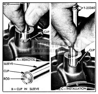
Replace inlet strainer if it is damaged or clogged so that it cannot be thoroughly cleaned, using Retainer Clip Replacer T-25360. Use small end of rod of tool to remove retainer clip. To install clip, place it in tapered end of tool sleeve then use rod inside sleeve to push clip into place. See figure 3-67.
1950 Buick Removing and Installing Retainer Clip
- Float Needle Valve and Seat. Because of the wear that normally occurs in these parts and the necessity of having a tight seating valve, it is advisable to replace these parts if the carburetor has been used for considerable mileage. Even if mileage is low, replace these parts if needle is grooved or seat is damaged.
- Vacuum Power Piston and By-Pass Jet. Make certain that the surface of the piston is thoroughly clean. Do not use any abrasive material for polishing the piston surface. Inspect for wear or damage. Replace if necessary. Test by-pass jet for tight seating by sucking on the upper end. Replace jet if doubtful.
- Main Body. Make certain the main body is thoroughly clean and that all passages are free of foreign material. Check high speed and idle air bleeders for correct sizes, using a drill shank as a gauge. For drill sizes see 1950 Buick Stromberg Carburetor Calibrations, Paragraph 3-1.
Replace pump strainer if it is damaged or clogged so that it cannot be thoroughly cleaned. Use Retainer Clip Replacer T-25360 as previously explained but use shouldered end of sleeve for installing retainer clip. See figure 3-67.
- Main Discharge Jets and Idle Tubes. Inspect tips of main discharge jets to make certain that they are not damaged, and that walls are not distorted so as to deform the holes. Test idle tubes by blowing or sucking to make sure that metering holes are clear. Inspect small ends to make sure that they are not damaged so as to deform the metering holes.
Replace any parts whose condition appears doubtful.
- Pump Piston, Discharge Nozzle and Related Parts. Inspect pump piston leather washer for cracks, creases, turned edges, or other damage. Test relief valve in piston for tight seating by blowing on lower end of piston; if valve is seating tightly it will not be possible to blow through it.
Test discharge nozzle by sucking or blowing to make sure that all holes are clear. It is advisable to replace pump inlet and discharge channel check valve balls since these parts are small and difficult to inspect.
Inspect check valve ball seats in main body with a good light. If a seat appears rough, place ball in seat and tap lightly to swage a good seat, then discard the ball.
- Throttle Valve Body and Idle Needle Valves. Be sure that the idle discharge holes, the air bleeders, and the barrels of the throttle valve body are clean of all carbon deposits. A comparatively small amount of carbon in barrel may have the effect of decreasing the bore sufficiently to prevent the throttle valves resting at the correct angle when closed. This can have serious effects on performance because the distance from the throttle valve, when closed, to the edge of the idle discharge hole must be kept within close limits to the established dimension.
Check the size of the upper idle discharge hole by inserting the shank of the correct size drill. This has the further advantage of removing any foreign matter that may be obstructing the hole. The lower discharge hole for the idle needle valve should be checked in the same manner. For drill sizes see 1950 Buick Stromberg Carburetor Calibrations (par. 3-1).
Inspect seats for idle needle valves for scoring or other damage. If ends of idle needle valves are grooved or bent, replace the valves.
Check wear of throttle stem bearing. There should not be more than about .006″ play, otherwise air leaks will interfere with performance.
- Throttle Valves, Throttle Lever and Stem Assembly. See that throttle valves are not bent and do not have burrs or sharp edges. Replace if damaged.
Inspect throttle lever and stem assembly for wear on bearing surfaces. Check pump rod holes for wear and also see that lever is not loose on stem. Replace if necessary.
- Accelerator Vacuum Switch. Disassemble, clean, inspect, and re-assemble vacuum switch as described in paragraph 10-33.
3-30 ASSEMBLY AND ADJUSTMENT OF 1950 BUICK STROMBERG CARBURETOR AND CHOKE
Assembly of Carburetor
When assembling the carburetor use all new gaskets and any additional new parts found to be necessary during inspection.
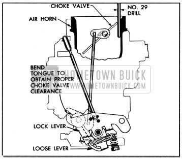
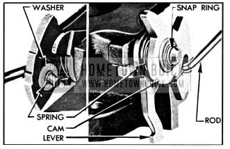
- Attach fast idle rod to fast idle cam with washer and hook the cam spring into groove in rod. Install spacer washer, loose lever lock lever, and fast idle cam on post in throttle body, then install snap ring in groove in post. See figure 3-68.
1950 Buick Lock Lever, Fast Idle Cam and Rod
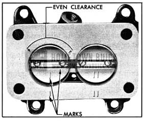
1950 Buick Correct Position of Throttle Valves
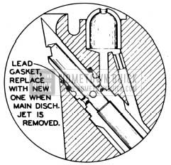
1950 Buick Position of Main Discharge Jet and Gasket
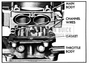
1950 Buick Location of Idle Channel Wires
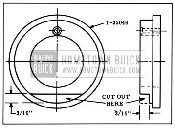
1950 Buick Alteration of First Type Gauge T-25046
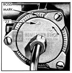
- Install Gauge T-25046 so that the small hole fits over the pin on choke lever and outer flange of gauge pilots in choke housing. Turn gauge until the two indicator lines on face of gauge are centered on the end of indicator boss on choke housing. See figure 3-73.
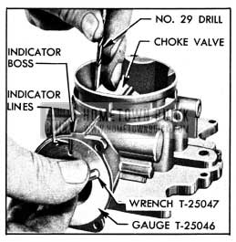
1950 Buick Setting Choke Valve and Vacuum Piston
1950 Buick Stromberg Choke Thermostat Setting
- With air horn inverted, place Float Gauge T-24971 on top of gasket so that the locating buttons on gauge fit in holes in air horn. Gauge must rest flat and solid on the gasket. See figure 3-75.
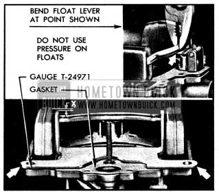
1950 Buick Checking and Adjusting Float Height
Installation of Carburetor
- Make sure that carburetor gasket is in good condition; then install carburetor on intake manifold.
- Clean the gasoline filter (par. 3-7), install it on carburetor, and connect the gasoline pipe. Connect the vacuum spark control pipe.
- Connect the choke upper heat pipe to choke thermostat cover, avoiding excessive tightening which may change the position of cover and affect thermostat setting.
- Connect and adjust throttle linkage as described in paragraph 3-8.
- Connect the accelerator vacuum switch wires and check switch timing as described in paragraph 10-33.
- Install air cleaner and silencer.
- Adjust carburetor as described in paragraph 3-10.
Leave A Comment
You must be logged in to post a comment.