SECTION 13-C 1950 BUICK WINDSHIELD WIPERS – CLOSED BODY WINDSHIELD, WINDOW GLASSES AND VENTILATORS
13-10 1950 BUICK WINDSHIELD WIPERS
Description of 1950 Buick Windshield Wiper
The 1950 Buick windshield wiper motor is mounted on an auxiliary drive which is attached to the front face of the cowl panel. The motor shaft is coupled to a short shaft in auxiliary drive which extends through the cowl panel. The rear end of the auxiliary drive shaft has a cross lever with swivel connectors to which the wiper transmission cables are attached.
One end of the cable which actuates each 1950 Buick windshield wiper transmission is attached to the swivel connector on one end of driver shaft lever and the other end of cable is attached to connector on opposite end of lever. The loop of the cable runs outward and around pulleys on a cable tensioner mounted on rear side of dash panel, then rearward and around the driven pulley in the wiper transmission. The cable is clamped to the driven pulley to insure positive drive. The cable tensioner has a spring and ratchet which operate to automatically take up slack and maintain proper tension on cables.
The 1950 Buick windshield wiper cables require occasional lubrication preferable each time the chassis and body is lubricated. Wipe a few drops of light engine oil on cable where they pass over the tensioner pulleys.
CAUTION: 1950 Buick windshield wiper arms must not be rotated by hand for any reason as this places an undue strain on the cable fastenings.
The tube which connects the wiper motor to engine intake manifold is attached to a valve on
the motor. The motor valve is actuated by a bowden cable extending from a control mounted on left end of instrument panel. The 1950 Buick windshield wiper is operated, with engine running, by turning control knob clockwise. When car is equipped with a windshield washer the wiper control contains a button to control washer operation as described in paragraph 11-2.
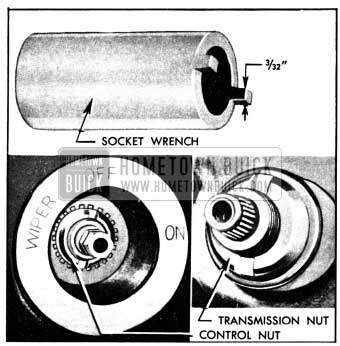
Control and Transmission Nut Socket Wrench
A special socket wrench is required for removing the windshield wiper control and transmission nuts for replacement of these units. A suitable tool may be prepared locally by altering a packing gland nut socket (Snap-On Tools No. TR-3 or J. H. Williams No. NMR-8) as shown in figure 13-13. The 1/8″ prongs are filed to a width of 3/32″.
1950 Buick Control and Transmission Nut Socket Wrench
Replacement of 1950 Buick Windshield Wiper Control
- Loosen clamp screw and disconnect control cable from wiper motor.
- Disconnect battery ground cable, then remove fuse block from instrument panel.
- Carefully pry control knob rearward to remove it from control valve shaft, to which it is retained by a small spring.
- Using special socket wrench (fig. 13-13) remove control nut and internal-tooth lockwasher then remove control from instrument panel. Disconnect windshield washer hoses if attached to control.
- When reversing above procedure to install the control, connect battery ground cable in proper manner to wind the clock (par. 10-66). Adjust the control cable at clamp screw on wiper motor so that valve is fully opened when control knob is at “ON” position.
Removal and Installation of 1950 Buick Windshield Wiper Transmission
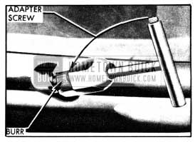
The transmission shaft extends upward through the 1950 Buick windshield rubber channel and the reveal molding. A driving burr which is pressed on the splined upper end of the shaft for attachment of the wiper arm must be removed with a special tool whenever the transmission or the windshield reveal molding is to be removed.
- Remove blade and arm from driving burr on wiper transmission shaft.
- Remove adapter screw from handle of Burr Remover and Replacer J 2682 and thread it into the end of transmission shaft, then install the tool so that clutch end of barrel grips the under side of driving burr. Hold the barrel of tool stationary with an open end wrench, turn handle of tool counterclockwise until burr is removed. See figure 13-14.
1950 Buick Removing Driving Burr from Transmission Shaft
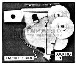
1950 Buick Cable Tensloner
While holding cables in pulleys, apply slight pressure to cable tensioner ratchet spring and rotate pulley support plate to remove pressure from temporary locking pin which will then fall out of holes. Slowly release pulley support plate until cables are tight, then release ratchet spring. CAUTION: Do not let pulleys snap against cables.
- Before installation of escutcheon and nut apply 3-M Autobody Sealer around base of wiper shaft and washer outlet.
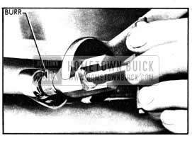
- Always install a new driving burr on upper end of transmission shaft and use Remover and Replacer J 2682 to press it into position. The bore of a new burr is not serrated; the splined shaft cuts serrations in the softer metal of burr during installation.
- Reverse the barrel on handle of tool J 2682 so that tapered end of barrel is toward threaded pilot of handle. Carefully place new driving burr on shaft so that it is squarely aligned, then screw the threaded pilot of tool handle into end of transmission shaft. See figure 13-16.
1950 Buick Installing Driving Burr on Transmission Shaft
13-11 1950 BUICK BELT, HEADER, AND REVEAL MOLDINGS
IMPORTANT: Belt, header, and reveal moldings must not be pried loose as they are retained by clips and bolt type retainers.
This paragraph contains replacement procedures on all classes of external chrome moldings at windshield and window openings.
Replacement of Front End Belt Molding
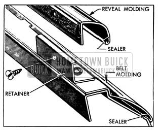
The right hand section of front end belt molding overlaps the left hand section at the center. Three bolt type retainers attach each section of molding and one retainer attaches both sections where they overlap at the center. Rubber sealing washers are placed on each retainer bolt between the molding and cowl panel. See figure 13-17. A single screw attaches outer end of each molding to the body pillar.
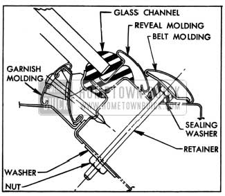
1950 Buick Sectional View of Belt and Reveal Moldings at Bottom of Windshield
- Remove both 1950 Buick windshield wiper arms, driving burrs, transmission nuts and escutcheons (par. 13-10).
- Remove defroster air scoop from right side of cowl panel and remove glove box from instrument panel.
- Remove screws attaching ends of belt molding to body pillar, then remove nuts and washers from belt molding retainer bolts located along defroster duct under cowl. See figure 13-17. Remove molding with retainer and sealing washers from outside of body.
- Before installing belt molding, place sealing washer on retainer bolts, then apply 3-M Weatherstrip Adhesive to bolt holes and to bolts around the sealing washers. See figure 13-18.
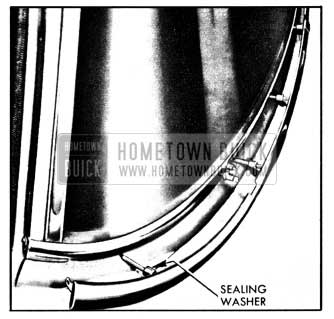
1950 Buick Installation of Belt Molding with Retainers and Sealing Washers
Replacement of 1950 Buick Windshield Header Molding
The right hand section of 1950 Buick windshield header molding overlaps the left hand section at the center. The sections are attached by six bolt type retainers having barrel nuts located in the windshield header under the headlining. Rubber sealing washers are placed on retainer bolts between the molding and roof panel. See figure 13-19. A single screw attaches outer end of each molding to the body pillar.
1950 Buick Sectional View of Windshield Header Molding Installation
- Remove screws attaching ends of molding to body pillar.
- Remove rear view mirror. Remove escutcheon, both 1950 Buick windshield garnish molding sections and the defroster air deflectors attached to moldings with clips. NOTE: When removing right garnish molding, detach radio antenna lead-in cable by removing clips which attach cable to molding.
- Loosen headlining along windshield header and through openings in header remove the six barrel nuts from header molding retainer bolts.
- Remove header molding with retainers and sealing washers from outside of body.
- Before installing header molding, place sealing washers on retainer bolts, then apply 3-M Weatherstrip Adhesive to bolt holes and to bolts around the sealing washers.
- Install header molding, place barrel nuts on retainer bolts and tighten firmly. Apply adhesive to screw holes at outer ends of molding sections and install attaching screws.
- Tack headlining to windshield header and install garnish molding and rear view mirror. NOTE: When installing right garnish molding, attach antenna lead-in cable to molding with clips as described in paragraph 11-9 (c, step 7).
Replacement of 1950 Buick Windshield Reveal and Center Division Moldings
1950 Buick windshield reveal moldings are attached by clips inserted into a groove of the windshield glass rubber channel. They cannot be replaced except when the 1950 Buick windshield glass and channel assembly is removed from body opening as described in paragraph 13-13.
The 1950 Buick windshield outer division molding used with two piece windshields is retained by barrel nuts in the inner division molding. The lower end of outer molding is retained by the front end belt molding.
To remove outer division molding, remove belt molding retainer nut and washer at center of body under instrument panel, remove barrel nuts from inner division molding, then remove outer molding. Before installing molding, seal around molding retaining screw holes on glass rubber channel with 3-M Autobody Sealer.
Replacement of 1950 Buick Rear Quarter Belt
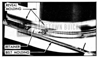
The right hand section of rear quarter molding overlaps the left hand section at the center. The sections are attached by bolt type retainers and the ends are attached to body lock pillars by screws. On Style “69” each section is also retained at lower corner of back window by a retainer attached to body panel.
- On Style “19” only:
- Remove rear seat cushion and back (par. 13-21).
- Remove rear quarter garnish and belt finishing moldings as a unit.
- Remove rear quarter trim pad far enough to uncover inspection hole in rear quarter inner panel. Trim pad is tacked along the forward edge and anchored at upper rear corner with a drive nail.
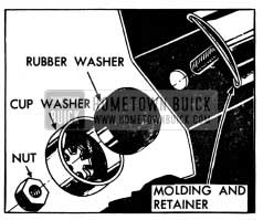
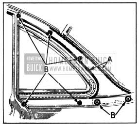
- Through inner panel inspection hole “A” remove the rear quarter belt molding retaining nut, cup washer and rubber washer. See figure 13-22.
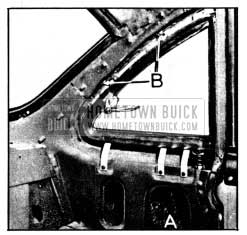
1950 Buick Rear Quarter Ventilator Inside Area
1950 Buick Rear Quarter Belt Molding Installation
1950 Buick Rear Quarter Belt Molding Retainer-Style 69
Replacement of 1950 Buick Rear Quarter Ventilator
- Remove 1950 Buick rear quarter belt molding (subpar. d, above).
- Above rear quarter ventilator at “B,” inside the body, remove the two barrel nuts and washers securing the header molding. See figure 13-22.
- Remove the single screw holding end flange of header molding to body lock pillar, then remove the two screws holding lower end of molding to rear quarter panel.
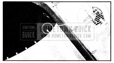
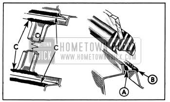
- Before installing header molding, apply continuous heads of 3-M Autobody Sealer to metal flanges of rear quarter pillar from lower corners upward as indicated at “A” in figure 13-23. Circle each screw hole with sealer as indicated at “B.”
1950 Buick Sealing of Ventilator Header Molding
Replacement of 1950 Buick Back Window Reveal Moldings
Reveal moldings on the one-piece back windows are attached by bolt type retainers, except on first jobs which use clips and bolts.
Lower reveal moldings on three-piece back windows are retained by clips on all jobs. Upper reveal moldings are attached by bolt type retainers, except on first jobs which use clips. Bolted upper reveal moldings may be identified by retainer nuts located under the inner lip of window glass rubber channel under the garnish molding.
The clips which retain back window reveal moldings are inserted into grooves in the window glass rubber channel. Clipped moldings can only be replaced after the glass and channel assembly is removed from window opening, as described in paragraph 13-14 (one-piece) or 13-15 (three-piece).
Back window reveal moldings attached by bolt type retainers can be replaced without disturbing the window glass. The retainer bolt nuts can be reached by removing the window garnish molding.
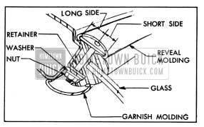
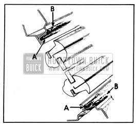
Use new retainers when installing reveal molding, since old ones have been cut off after installation. Place retainers in molding with short side of plate toward the inner or glass side of molding. See figure 13-24.
1950 Buick Reveal Molding Retainer Installation
Seal retainer bolts with 3-M Weatherstrip Adhesive before installation of molding. After installation, draw nuts up firmly then cut off surplus ends of bolts to provide clearance when garnish molding is installed.
Replacement of 1950 Buick Door Lower Reveal Molding
- Remove 1950 Buick door trim pad (par. 13-18) and inspection hole cover from door inner panel.
- Remove the four screws attaching cam to lower sash channel (fig. 13-35) and lower the window glass below sill of window opening.
- On front door only, remove door ventilator (par. 13-17) and remove rivet attaching rear end of reveal molding to flange of door at lock pillar.
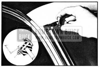
- Remove screws attaching molding to retainers on door, then lift molding up to remove it. See figure 13-25.
1950 Buick Door Lower Reveal and Belt Molding Attachments
Replacement of 1950 Buick Door Belt Molding
- Remove 1950 Buick door lower reveal molding (subpar. g, above).
- Remove screws and reveal molding retainers along lower edge of window opening, then remove belt molding. See figure 13-25.
- Before installation of belt molding, apply 3-M Autobody Sealer along inside of outer curled edge (fig. 13-25), and to all retainer screw holes, then install molding by reversing procedure for removal.
Replacement of 1950 Buick Door Upper Reveal Molding
- Remove 1950 Buick garnish molding and upper section of glass run channel (par. 13-16, band c).
- On front door only, remove door lower reveal molding (subpar. g, above) and ventilator rain deflector.
On rear door only, remove rear reveal molding if this molding is present. On door having stationary window, remove screw retaining escutcheon to header at upper forward edge of stationary glass.
- On doors having a header molding installed over the reveal molding, loosen door weatherstrip and remove screws retaining header molding to door flange.
- Remove reveal molding retaining clips from pinchweld of door header and remove molding. Clips on front doors are spring type that snap over pinchweld flange. Clips on rear doors are retained by screws.
- Before installation of reveal molding apply 3-M Autobody Sealer along inside of outer curled edge, then install molding by reversing the removal procedure.
Replacement of 1950 Buick Rear Quarter Reveal Moldings
- Remove upper garnish molding and upper section of glass run channel (par. 13-16, band c).
- Remove reveal molding escutcheon and upper reveal molding retaining screws from inside body and remove these parts.
Remove 1950 Buick rear quarter window glass (par. 13-16), remove lower reveal molding retaining screws, then lift up lower reveal molding to free it from retainers mounted along lower side of window opening.
- Before installation of moldings apply 3-M Autobody Sealer along inside curled edge, then install by reversing the removal procedure. When installing glass run channel make sure that lower rear end is first threaded into its retaining spring clip.
13-12 1950 BUICK TWO-PIECE WINDSHIELD GLASS REPLACEMENT
This paragraph covers the replacement of one glass of a two-piece 1950 Buick windshield which does not have a chrome reveal molding fitted into the rubber glass channel. Where reveal moldings are not used one glass can be replaced without disturbing the other glass.
On a two-piece 1950 Buick windshield having chrome reveal moldings fitted into the rubber glass channel, the replacement of one half of windshield glass cannot be done unless the complete two-piece glass, channel, and molding assembly is loosened from the body opening. The procedure in this case is the same as described for one-piece windshields in paragraph 13-13 except that an outer center division molding must also be removed, and must be sealed when reinstalled.
Removal of 1950 Buick Windshield Glass
- Protect the finish by masking around the windshield opening and laying a suitable covering across the hood and front fender.
- Remove rear view mirror, escutcheons, inner division molding, and garnish molding behind glass being removed. NOTE: When removing right garnish molding detach antenna lead-in cable by removing clips which attach cable to molding.
- On first Series 40 only, remove defroster air deflector at bottom of windshield.
- With a putty knife, carefully loosen the rubber glass channel from the pinchweld flange and loosen the lip of channel from the glass being removed.
- With the palm of hand against inside surface of glass, carefully force the glass and channel outward until the lip of rubber channel is removed from the pinchweld flange of body opening. Apply pressure alternately at upper and lower outer corners of glass until separation begins. When assembly is free from body opening disengage the glass from rubber channel and remove it.
Installation of 1950 Buick Windshield Glass
- Thoroughly clean old sealing compound from glass channel and pinchweld flange, using a cloth saturated with oleum spirits and a scraper where necessary.
- Before 1950 Buick windshield glass is installed, carefully check the pinchweld flange for high spots which would impart a strain on the glass. Use the glass as a template to check flange for proper contour to fit the glass. Correct any irregularities by filing or hammering.
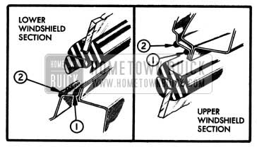
- Apply a continuous 3/1 6″ to 1/4″ bead of 3-M Autobody Sealer in outer corner of pinchweld flange, completely around the opening, as indicated at “A” in figure 13-26.
1950 Buick Location of Sealing Compounds
1950 Buick Pulling Lip of Channel Over Pinchweld Flange
13-13 1950 BUICK ONE-PIECE WINDSHIELD GLASS REPLACEMENT
The 1950 Buick one-piece windshield glass is mounted in a molded rubber channel which fits over a pinchweld flange formed by the body panels around the windshield opening; The procedure for removal and installation of the glass and channel is the same on all bodies, with the exception of variations caused by differences in the reveal moldings and header moldings where used.
The “07” and “69” body styles employ reveal moldings consisting of a full width upper section, a two-piece lower section, right and left side sections and escutcheons at upper corners.
The “19” body styles employ reveal moldings consisting of full width upper and lower sections, right and left side sections covering the body pillars, and an additional two-piece “windshield header molding” running across the front end of roof panel and partially covering the upper reveal molding.
The “37” body styles employ reveal moldings consisting of right and left upper sections joined at the center under an escutcheon, right and left lower sections joined at the center, and right and left side sections covering the body pillars.
This paragraph covers the replacement of a one-piece windshield glass having any type of reveal molding. The procedure also applies to the replacement of two-piece windshield glasses where a reveal molding is fitted into the rubber glass channel. In the latter case, an outer center division molding must also be removed and the screw holes must be sealed when molding is reinstalled.
Replacement of 1950 Buick Windshield Glass Only
When a 1950 Buick windshield glass is broken by accident or other condition which does not indicate a fault in windshield mounting, it is not necessary to remove the complete windshield glass channel, and reveal moldings in order to replace the glass unless the channel and moldings are also damaged.
The 1950 Buick windshield glass may be removed from the rubber channel by loosening channel from body opening along the top and sides only, leaving the bottom side attached. When glass and channel are pushed outward from opening at the top and reveal moldings are removed from rubber channel, the old glass can be removed and new glass installed in the channel without difficulty.
Subparagraph b below gives the procedure for complete removal of glass, channel, and all moldings. To remove glass only, perform steps 1 through 3b, then loosen glass and channel and remove glass as described in step 5 and 6.
Subparagraph c below gives the procedure for complete installation of glass, channel, and all moldings. When installing glass only, clean, inspect, and seal glass channel and pinchweld flange as specified, place glass in rubber channel, then use the cord method to fold lip of channel over the pinchweld flange. Complete the installation by reinstalling all parts removed.
Removal of 1950 Buick Windshield Glass, Channel and Moldings
- Place suitable coverings over hood, front fenders, and instrument panel to protect finish. Also apply masking tape adjacent to windshield assembly to cover any exposed finish on upper front body pillars and roof panel of car in the working area.
- Remove 1950 Buick rear view mirror. Remove escutcheon, both windshield garnish molding sections and the defroster air deflectors attached to moldings with clips. NOTE: When removing right garnish molding, detach radio antenna lead-in cable by removing clips which attach cable to molding.
- On Style “07” or “69” body, remove reveal molding upper corner escutcheons. These are attached by a bolt running through the glass channel with nut inside the body. See figure 13-28.
1950 Buick Reveal Molding Corner Escutcheon
On Style “19” body, remove windshield header molding (par. 13-11, b), also remove screws attaching the side reveal moldings to body pillars.
On Style “37” body, remove radio antenna par. 11-9, d) and reveal molding escutcheon, also remove screws attaching the side reveal moldings to body pillar.
- Remove the front end belt molding (par. 13-11, a).
- First, use a putty knife to loosen the seal between rubber channel and pinchweld flange. Then, with a helper stationed on the outside of the body, carefully force the assembly outward with palm of hand against inside surface of glass, starting at either upper corner and working across top of assembly as the separation of channel lip from pinchweld progresses. Move entire upper portion of assembly forward, then work out the bottom section of the rubber channel so that it clears the wiper transmission shafts and lower pinchweld. If interference between lower reveal molding and wiper transmissions prevents removal of assembly, release the lower molding from rubber channel before attempting to remove assembly. Lift the glass, channel, and reveal molding clear of body and place it on a bench.
- Curl back the lip of glass channel and remove reveal moldings, then remove the channel from windshield glass.
Installation of 1950 Buick Windshield Glass, Channel and Moldings
- Thoroughly clean old sealing compound from glass channel and pinchweld flange, using a cloth saturated with oleum spirits and a scraper where necessary.
- Carefully check the pinchweld flange for high spots which would impart a strain on the glass. Use the glass as a template to check flange for proper contour to fit the glass. Correct any irregularities by filling or hammering the flange.
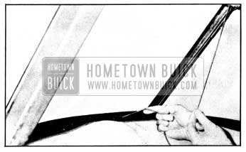
- With new glass on a bench, install the rubber channel around edges of glass. DO NOT PRY EDGE OF GLASS WITH A METAL TOOL. Insert a strong cord into the pinchweld groove of rubber channel. Referring to figure 13-29, start at upper corner indicated at “A,” then follow across the top, down the side, and along the bottom to the wiper shaft section.
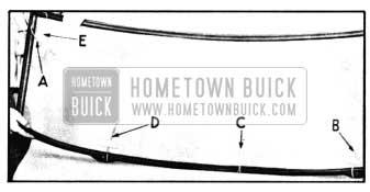
1950 Buick Assembly of Glass and Rubber Channel
At this point, make a loop in the cord and into this loop between the wiper shaft and washer tube holes insert a short section of cord indicated at “B.” At bottom center of long cord make another loop indicated at “C.” At opposite wiper section of channel indicated at “D” loop the cord and insert another short section. Follow up the remaining side and cross both ends of the cord at the upper corner indicated at “E.” Tape ends of cord to inside surface of glass as illustrated.
1950 Buick Location of Windshield Sealing Compounds
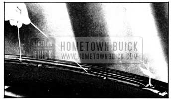
1950 Buick Pulling Lip of Channel Over Pinchweld Flange View
On Style “19” body, apply 3-M Weatherstrip Adhesive to side reveal molding screw holes in body pillar then install reveal molding attaching screws. Seal and install windshield header molding (par. 13-11, b).
On Style “37” body, apply a bead of 3-M Autobody Sealer to reveal molding escutcheon and install escutcheon, then install radio antenna (par. 11-9, d).
- Apply 3-M Weatherstrip Adhesive to screw holes where reveal moldings are attached to body pillar and install attaching screws.
- Seal and install front end belt molding (par. 13-11, a).
- Complete the installation by reversing procedure for removal of remaining parts. NOTE: When installing right garnish molding, attach antenna lead-in cable to molding with clips as described in paragraph 11-9 ( c , step 7).
13-14 1950 BUICK ONE-PIECE BACK WINDOW GLASS REPLACEMENT
A one-piece back window glass, mounted in a rubber channel, is used on the “Jetback” bodies (Styles “07” and “08”). Chrome reveal moldings cover the rubber channel except on the “standard” Series 40.
The reveal moldings consist of right and left upper sections joined at the center, and right and left lower sections joined at the center and overlapping the upper sections at the lower corners. First production reveal moldings are retained by clips and four bolt type retainers. On later production bodies, bolt type retainers are used for molding retention completely around the opening.
Removal of 1950 Buick Back Window Glass and Reveal Moldings
- Apply a protective covering over rear compartment lid, also masking tape over the paint surfaces adjacent to back glass around entire opening.
- Remove back window garnish molding by removing all attaching screws.
- From inside body on styles with chrome reveal moldings, remove reveal molding retainer nuts and washers from under lip of glass channel around entire opening. From outside body, remove sections of reveal molding then mark location of molding bolt holes on adjacent masking tape as an aid when reinstalling glass assembly. NOTE: If clips also retain the reveal moldings, the moldings cannot be removed until the entire glass and rubber channel assembly has been removed from the opening.
- With a flat blade tool, loosen rubber channel from sealer around opening.
- Apply moderate hand pressure against inside surface of glass to release rubber channel from pinchweld flange. Start at curved upper corner on one side of opening and continue across top of glass as separation of the rubber channel from the pinchweld progresses.
- From outside body with the aid of a helper, lift assembly up to free it from lower flange and remove from opening. Place on a bench.
- Remove chrome reveal moldings, if clipped to rubber channel, by curling back channel lip. Then, loosen glass from sealer around outer lip of channel and remove glass.
Installation of 1950 Buick Back Window Glass and Reveal Moldings
- Thoroughly clean old sealing compound from glass channel and pinchweld flange, using a cloth saturated with oleum spirits and a scraper where necessary.
- Carefully check the pinchweld flange for high spots which would impart a strain on the glass. Use the glass as a template to check flange for proper contour to fit the glass. Correct any irregularities by filing or hammering the flange.
- Apply a continuous 3/16″ bead of 3-M Autobody Sealer in outer corner of pinchweld flange, completely around the opening, as indicated at “A” in figure 13-32.
1950 Buick Location of Back Window Sealing Compounds
If 1950 Buick reveal moldings are attached with clips and bolts , slide clips and NEW retainers into their approximate location in molding sections. The short side of retainer plate must be placed toward inner or glass side of molding. See figure 13-24. Seal ends of clips and shanks of retainer bolts with 3-M Weatherstrip Adhesive and install moldings with clips inserted into groove of rubber channel. NOTE: If clips are not used, moldings should be installed later (step 10).
- With a helper, lift glass and channel assembly into place in window opening and align bolt holes in channel with similar holes in pinchweld flange.
- While helper applies pressure to glass on outside, use the cord to pull the lip of rubber channel over the pinchweld flange on inside of body.
- Using trigger gun B 182-A, apply 3-M Weatherstrip Adhesive between outer lip of rubber channel and the glass all around the channel.
- If reveal molding is attached with bolt type retainers only, install NEW retainers in molding, apply sealer, and install molding over glass channel as described in step 5a above.
- On the inside of body thread nuts upon ends of molding retainer bolts, draw up to a snug fit, then cut off excess material from bolt ends to permit lip of rubber channel to cover the nuts. Install garnish molding.
13-15 1950 BUICK THREE-PIECE BACK WINDOW GLASS REPLACEMENT
The 1950 Buick three-piece back window glass assembly consists of a broad center section and two small curved side sections mounted. in a rubber channel. The side and center sections are separated by upright divisions and the rubber channel is covered by chrome reveal moldings.
The 1950 Buick reveal moldings consist of right and left upper and lower sections joined at the center. On Models 52 and 72 (style “19”) having the rear quarter ventilators, an additional “rear quarter ventilator header molding” covers the body area between the back window glass and the ventilators. The belt molding, which extends completely around the quarters and rear of body from door to door, consists of two sections joined at the center.
IMPORTANT: Reveal and belt moldings must not be pried loose as they are retained by clips and bolt type retainers. All lower reveal moldings, and the upper reveal moldings on first jobs, are retained by clips which cannot be released except when glass and channel are removed. Later production bolted upper reveal moldings can be replaced without disturbing back window glass. See paragraph 13-11 (f).
Removal of 1950 Buick Back Window Glass Assembly
- Apply masking tape around back window opening and place protective covers where necessary to protect finish and trim.
- Remove 1950 Buick rear seat cushion and backs (par. 13-21).
- On Style “69” only, remove arm rest extension strap retainer by removing two screws concealed under upper end of strap, then remove seat back trim valance by removing all screws attaching it to the shelf panel.
- Remove barrel nuts from both inner division moldings, then remove inner and outer moldings.
- Remove all screws, then remove the onepiece garnish molding.
- Remove belt molding (par. 13-11, d).
- On Style “19 ,” remove ventilator header moldings (par. 13-11, e).
- On Style “69,” remove screw which attaches the short reveal moldings to body lock pillar and carefully slide the moldings forward to release them from retaining washers. On some early jobs it may be necessary to release the retaining nut on inside of rear quarter after headlining is loosened.
- On inside of body, remove all upper reveal molding retaining nuts located under lip of glass channel, then on outside of body remove upper reveal molding sections. NOTE: Mark location of upper reveal molding bolt holes on masking tape around window opening as an aid when reinstalling glass assembly.
- With a flat blade tool, loosen the rubber channel from sealer around opening, then with a helper stationed on outside of body, apply moderate hand pressure against the glass from inside the body and carefully force the glass and its channel to release from the pinchweld flange. Start at one side and work across top of assembly to opposite side.
- From outside of body with the aid of a helper, grasp each end of loose back window assembly, lift up and remove assembly from opening. Place on a bench and remove lower reveal molding and rubber glass channel.
Installation of 1950 Buick Back Window Glass Assembly
- Thoroughly clean old sealing compound from glass channel and pinchweld flange using a cloth saturated with oleum spirits and a scraper where necessary.
- Carefully check the pinchweld flange for high spots which would impart a strain on the glasses. Use glasses for templates to check flange for proper contour. Correct any irregularities by filing or hammering.
- Apply a continuous 7’16” bead of 3-M Autobody Sealer in outer corner of pinchweld flange, completely around the opening, as indicated at “A” in figure 13-32.
- Apply a continuous 3/16″ bead of 3-M Weatherstrip Adhesive to outer corner of window opening rabbet, completely around the opening, as indicated at “B” in figure 13-32.
- On a bench, install window glass sections into the rubber channel, making sure that the etched trade mark on lower corner of each glass is at the bottom. DO NOT PRY EDGES OF GLASS WITH A METAL TOOL.
- Insert strong cords into the pinchweld and division bar grooves of rubber channel around each individual section of glass. Tape ends of cords to inside surface of glasses. See figure 13-33.
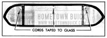
1950 Buick Channel and Cords Installed on Glasses
- Seal all screw and bolt holes in body panels and on glass rubber channel with 3-M Weatherstrip Adhesive.
- Seal and install ventilator header moldings as described in paragraph 13-11 (e).
- Seal and install belt molding as described in paragraph 13-11 (d).
13-16 1950 BUICK DOOR AND REAR QUARTER WINDOWS – CLOSED BODIES
NOTE: The Riviera, Style “37,” door and rear quarter windows are similar to the windows on convertible coupes except that they are manually operated by regulators instead of the Hydro-Lectric Power System. For service procedures on Style “37” windows refer to Section 13-E.
Description of 1950 Buick Windows
Each 1950 Buick door and 1950 Buick rear quarter window has a safety plate glass which slides vertically in felt glass run channels. The window opening is trimmed on the inside by a garnish molding along the top and sides and a belt finishing molding along the bottom. The window opening is trimmed on the outside by chrome reveal and belt moldings which are covered separately in paragraph 13-11. Fabric weatherstrips attached to the belt finishing molding and lower reveal molding seal the glass along lower side of window opening and assist in preventing vibration of the glass.
The lower edge of door and rear quarter window glass is sealed into a metal sash channel. A channel-shaped cam or track attached to the sash channel is engaged by knobs on the main and idler arms of the window regulator assembly mounted on door or rear quarter inner panel. A knob on the opposite end of regulator idler arm slides in a channel-shaped regulator cam or track mounted on inner panel. The cams cause the arms of window regulator to apply evenly distributed pressure on lower sash channel to raise or lower the glass without tilting and binding in glass run channels.
The procedures given in this paragraph are for door windows; however, the same general methods are applicable to replacement of similar parts of the rear quarter windows. The principle difference is that rear quarter windows do not have window division channels.
Replacement of 1950 Buick Garnish and Inside Belt Finishing Moldings
- On front door remove ventilator regulator handle by pushing inward on the escutcheon and removing handle retaining spring, using Door Handle Pliers KMO 601. See figure 13-37.
- Remove garnish molding attaching screws, then grasp upper horizontal portion of molding and pull away from door with a downward motion to release it. Remove the rubber grommets which slip over lower ends of molding.
- Remove inside safety locking rod knob, remove retaining screws at both ends of belt finishing molding, then lift molding up to free it from retaining clips.
- Install moldings by reversing removal procedure.
Replacement of 1950 Buick Glass Run Channel
- Lower the window glass and remove garnish molding (subpar. b, above).
- Pry clips of upper section of door glass run channel from pinchweld flange of window opening and remove the upper section. When removing rear quarter glass run channel, remove the retaining screw at rear of window opening, pry channel toward inside of body to release retaining clips, then pull up to release lower end of channel from its retaining spring clip.
- To remove lower section of channel, remove trim pad (par. 13-18) and inspection hole cover adjacent to door lock pillar, then remove screw that retains lower end of channel to lock pillar. Pull channel up through window glass opening, using care to avoid denting the metal bead on channel.
- To install channel sections reverse the removal procedure. When installing rear quarter channel make sure that lower rear end is first securely engaged in its retaining spring clip.
Replacement of 1950 Buick Window Division Channel
- Remove 1950 Buick door trim pad (par. 13-18) and release the clips in the glass run channel adjacent to the window division channel and drop it down out of position.
- Remove the retaining screw holding upper end of division channel to door header and remove the two self-tapping screws attaching division channel to the top edge of door inner panel. See figure 13-34.
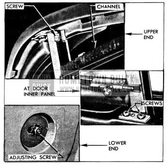
1950 Buick Window Division Channel Attachments
If channel is not properly positioned, adjust the lower end in or out, forward or rearward at the screw as required to obtain free movement of window glass.
Replacement of 1950 Buick Door Window Glass
- Remove 1950 Buick glass run channel and window division channel (subpar. c and d, above).
- With glass in lowered position, remove screws attaching the cam to lower sash channel. See figure 13-35.
1950 Buick Window Regulator and Cam Attaching Screws
Replacement of 1950 Buick Window Regulator
- Remove trim pad (par. 13-18). Remove inspection hole cover from door inner panel, also covering over small round hole in panel.
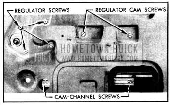
- With glass in lowered position, remove screws attaching the cam to lower sash channel and remove the cam. See figure 13-35.
- Remove four screws attaching window regulator, and two screws attaching regulator cam to door inner panel. Remove regulator and cam through inspection hole, using care to avoid scratching window glass.
- To install regulator and cam, set regulator in place, install cam over knob on idler arm and install regulator and cam attaching screws. The hole in inner panel for cam screw nearest lock pillar is slotted vertically. Set the screw at top of slot when tightening it.
- After installation of lower sash channel cam, raise and lower window glass several times to check for smooth operation of glass in run channels. If glass binds or has excessive edgewise play it will be necessary to adjust the window division channel (subpar. d). If glass tilts edgewise, adjust the regulator cam at slotted screw hole as required.
- Seal and install inspection hole cover, install covering over small hole in panel, and install door trim pad.
Replacement of 1950 Buick Rear Door Stationary Window
On Series 40 Style “08” bodies, the rear doors have small stationary window in place of ventilators.
- Remove door trim pad and window division channel (subpar. d, above).
- With a putty knife, free the glass channel from sealing compound all around window glass opening. From inside of door remove glass and channel assembly. Remove channel from glass. DO NOT PRY EDGE OF GLASS WITH METAL TOOL.
- Clean off old sealing compound from glass channel and metal of window opening, using oleum spirits and a scraper where necessary. When metal is dry, apply 3-M Weatherstrip Adhesive completely around rabbet wall of window opening in door.
- Install channel over edges of glass, then place a strong cord in rabbet groove of channel.
- Hold glass and channel assembly in place in window opening with ends of cord on outside. Pull out cord so that lip of channel is folded over rabbet wall, then press channel firmly into place against sealing compound.
- Reinstall division channel and trim pad, then seal between glass and outer lip of glass channel with 3-M Weatherstrip Adhesive, completely around the channel.
13-17 1950 BUICK DOOR AND REAR QUARTER VENTILATORS – CLOSED BODIES
NOTE: The Riviera, Style “37,” door ventilators are similar to the door ventilators on convertible coupes. For service procedures on Style “37” door ventilators refer to Section 13-E.
Description of 1950 Buick Ventilators
Each 1950 Buick ventilator has a safety plate glass sealed into a metal channel which is pivoted vertically. When a ventilator is closed it is sealed against passage of wind, water and dust by contact with a molded rubber weatherstrip attached to the door and the window division channel.
1950 Buick door ventilators are operated by a regulator mounted on the door inner panel. A bolt type lock riveted to the glass channel provides a lock for the ventilator. See figure 13-36.
1950 Buick Ventilator and Regulator Mounting
Rear quarter ventilators have a friction mechanism to hold ventilator in desired position and an inside locking handle. The friction mechanism is a part of the ventilator frame and consists of a heavy coil spring mounted on the frame spindle to exert frictional force against the mounting support. The spring pressure is set at the factory to give the best possible balance between ease of operation and resistance to closing under wind pressure, and usually will not require further adjustment. If the ventilator does not remain in set position when car is in motion, the spring pressure and friction may be increased by removing the ventilator assembly and tightening the nut at lower end of ventilator frame spindle.
1950 Buick Door Ventilator Regulator Adjustment
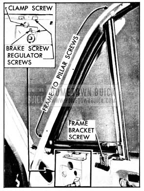
Excessive play at ventilator lower pivot may be corrected by tightening the clamp screw which attaches the glass channel T-shaft to ventilator regulator. See figure 13-36.
Excessive looseness or tightness in operation of the ventilator regulator may be corrected by adjusting the screw which controls the brake or friction clamp on the regulator. See figure 13-36.
To tighten the clamp screw or adjust the brake screw it is necessary to loosen door trim pad sufficiently to provide access to these screws (par. 13-18).
If ventilator glass does not fit evenly, up and down, against molding on window division channel, or ventilator lock does not slide to locked position with moderate pressure, it is usually necessary to adjust the division channel. This adjustment, however, should be limited so as not to cause a looseness or bind in the fit of the door window. See paragraph 13-16 (d).
In some cases of misalignment of ventilator in door opening it may be necessary to loosen the ventilator frame and the weatherstrip and shift these parts slightly. When proper alignment is secured the frame must be tightened securely and the weatherstrip must be cemented to window reveal with 3-M Weatherstrip Adhesive.
Replacement of 1950 Buick Ventilator Regulator
- Remove 1950 Buick garnish molding and door trim pad (par. 13-18) and remove inspection hole cover located below ventilator.
- Remove clamp screw which attaches glass channel T-shaft to regulator, also the regulator attaching screws. See figure 13-36.
- Remove regulator through inspection hole in door inner panel.
- Install regulator by reversing the removal procedure. Adjust the brake screw (fig. 13-36) to provide proper operating tension on regulator before attaching trim pad.
Replacement of 1950 Buick Door Ventilator Assembly
- Remove 1950 Buick ventilator regulator (subpar. b, above).
- Remove window division channel (par. 13-16, d).
- Remove screw attaching ventilator frame bracket to door inner panel, and screws attaching frame to door hinge pillar. See figure 13-36.
- Carefully . loosen weatherstrip where cemented to window reveal, then remove ventilator assembly.
- When ventilator assembly is installed by reversing removal procedure, apply 3-M Autobody Sealer between contacting surfaces of ventilator frame attaching brackets and door inner panel. Also apply a bead of 3-M Weatherstrip Adhesive on lip of weatherstrip at ventilator upper pivot to bridge the cutout in retainer at this point. Seal between lip of weatherstrip and the reveal moldings.
I need a price and availability for wiper motor for my 2 Door 1950 Buick model 46D. Plz advise