SECTION 3-A 1950 BUICK ENGINE FUEL AND EXHAUST SYSTEMS SPECIFICATIONS AND DESCRIPTION
3-1 SPECIFICATIONS
Tightening Specifications
Use a reliable torque wrench to tighten the parts listed, to insure proper tightness without straining or distorting parts. These specifications are for clean and lightly lubricated threads only; dry or dirty threads produce increased friction which prevents accurate measurement of tightness.
General Specifications
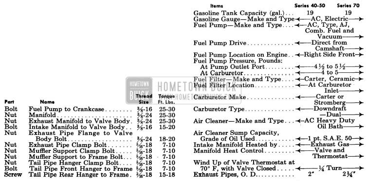
1950 Buick Engine Fuel and Exhaust Systems Tightening Specifications
1950 Buick Engine Fuel and Exhaust Systems Tightening Specification
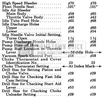
Carter Carburetor and Choke Calibrations
IMPORTANT: Calibrations are identified by the CODE NUMBER and not by model number. Carburetors of same model number but different code numbers are not interchangeable.
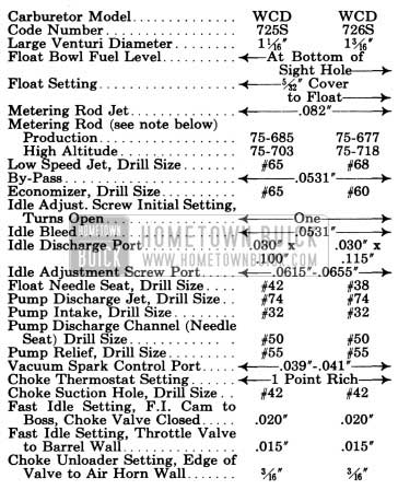
1950 Buick Carter Carburetor and Choke Calibrations Specifications
NOTE: Use production main metering jet for altitudes up to 3500 feet. Use high altitude metering rods for altitudes above 3500 feet.
Stromberg Carburetor Calibrations
IMPORTANT: Calibrations are identified by the CODE NUMBER and not by model number. Carburetors of same model number but different code numbers are not interchangeable.
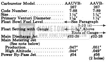
1950 Buick Stromberg Carburetor Calibrations Specifications
1950 Buick Stromberg Carburetor Calibrations Specification
NOTE: Use production main metering jet for altitudes up to 3500 feet. Use high altitude jet for 3500 to 9000 feet. Above 9000 feet use jet .002″ smaller than specified for high altitude.
3-2 DESCRIPTION OF FUEL SYSTEM
Gasoline Tank and Feed Pipes
The gasoline tank is made of two halves ribbon-welded together at the central flanges. Two internal braces spot-welded to the upper half on the centerline of tank at the support seats act as struts to maintain the shape of tank and prevent its flexing from the weight of gasoline and pull of supporting straps.
The filler is securely soldered into an opening in upper half of tank and is supported by an upper and a lower brace soldered to filler and tank. An external vent pipe soldered into the highest point of tank and into the upper end of the filler, and a groove formed in the upper end of filler where the filler cap seats, provide a protected air vent for the tank.
The gasoline tank is attached by two strap type supports to the body under the trunk compartment, where it is seated against strips of anti-squeak material. The rear feed pipe, which is connected to the gasoline gauge tank unit is supported by clips on the body. The rear feed pipe and the front feed pipe, which is connected to the fuel pump, are joined by a rubber hose which provides the flexibility required by movement of the engine on its rubber mountings. Flared type fittings are used at all other feed pipe connections.
Fuel Pump and Gasoline Filter
The combination fuel .and vacuum pump is mounted on the right side of crankcase at the front end and is driven directly from the engine camshaft. The construction and operation of the pump assembly is described in Section 3-D (par. 3-14).
A Carter ceramic type gasoline filter is located at the gasoline inlet of the carburetor for the purpose of removing any dirt and water which may pass the filter built into the fuel pump. The filter consists of a glass sediment bowl and a strainer which may be removed for periodic cleaning. See figure 3-7. The incoming gasoline flows into the sediment bowl and then flows upward through the strainer and into the carburetor.
Carburetor and Automatic Choke Assembly
Engines on all series are equipped in production with either Stromberg or Carter carburetors of the dual-barrel down draft type. Either make of carburetor is considered “standard” and it is not intended that these units be interchanged to provide “optional” equipment.
The carburetor assembly incorporates an automatic choke and an accelerator vacuum switch. The construction and operation of the Carter carburetor and choke assembly is described in Section 3-E (par. 3-19 and 3-20) and the Stromberg assembly is described in Section 3-F (par. 3-26 and 3-27). The accelerator vacuum switches on both carburetors are described in Section 10-E (par. 10-32 and 10-33).
A thick fibre gasket is used between the carburetor and the intake manifold to insulate the carburetor from the heat of the manifold.
Air Cleaner and Intake Silencer
All series engines are equipped with heavy duty oil bath air cleaners combined with intake silencers. The air cleaner removes abrasive dust and dirt from the air before it enters the engine through the carburetor. The intake silencer reduces to a very low level the roaring noise made by the air as it is drawn through the intake system. The cleaner and silencer also functions as a flame arrester in event of “back-fire” through the intake system.
On Series 40-50, the air cleaner and silencer is mounted crosswise of the engine, with the silencer supported by a bracket on the rocker arm cover. On Series 70, the air cleaner and silencer is mounted lengthwise of engine, with air cleaner supported on intake manifold.
The air cleaner consists of an oil sump and a cleaner element containing a filtering mesh which nests down into the sump above the oil level. The sump is filled with S.A.E. 50 engine oil to a predetermined level.
Incoming air passes downward through the passage between the oil sump and cleaner element, impinges on the surface of the oil and turns upward into the cleaner element. The air carries oil into the element to coat the finely divided filtering mesh. The air is thus exposed to a large oil wetted surface to which the dirt and impurities adhere. The cleaned air then passes through the silencer and into the carburetor. See figure 3-1.
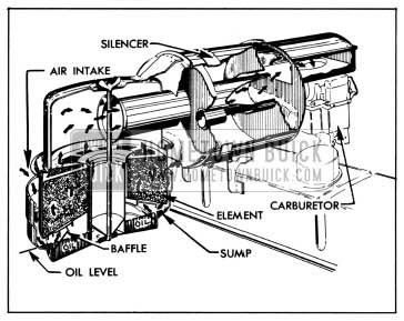
1950 Buick Air Cleaner and Silencer-Series 40-50
When the throttle is closed, any excess oil on the filtering mesh drips back into the sump
carrying the collected dirt with it. This dirt then settles to the bottom of the sump.
Carburetor Throttle Control Linkage
The carburetor throttle control linkage is designed to provide positive control of the throttle valves through their entire range without being affected by movement of the engine in its rubber mountings. The linkage also serves to operate the accelerator vacuum switch when cranking the engine.
The accelerator pedal is connected by a rod and ball joint to an accelerator lever on the lower end of a vertically mounted equalizer shaft. The equalizer shaft is supported at the lower end by a bracket attached to the dash and supported at upper end by a bracket attached to the intake manifold. A throttle operating lever on upper end of equalizer shaft is connected by a rod and ball joint to the throttle shaft lever on carburetor. The throttle return spring is connected to the throttle operating lever on equalizer shaft and to a boss on intake manifold. See figure 3-8.
On cars equipped with Dynaflow Drive, a dash pot is included in the throttle control linkage to prevent engine stalling when the accelerator pedal is suddenly released while driving. The dash pot cushions the closing of the throttle to prevent sudden shut off. The dash pot operating lever and adjusting screw are mounted on the lower end of accelerator equalizer shaft so that the adjusting screw contacts the plunger of dash pot, which is mounted on the equalizer shaft lower bracket. See figure 3-9.
On first Series 40 the dash pot is a vacuum type, being connected to the intake manifold by a pipe. On later Series 40 and all Series 50-70 the dash pot is an atmospheric type and is not connected to the intake manifold. See figure 3-9. In both types a diaphragm and calibrated air bypass controls the closing of the throttle valves.
3-3 DESCRIPTION OF INTAKE AND EXHAUST SYSTEM
Intake and Exhaust Manifolds
The intake and exhaust manifolds are separate units jointed together by a valve body through which hot exhaust gasses may be directed into a heat jacket cast on the intake manifold to heat the area below the carburetor.
The intake manifold is of dual type with the carburetor mounted at the middle. The outside barrel of the carburetor feeds into the outside branch of the manifold to supply fuel to Nos. 1, 2, 7, and 8 cylinders while the inside barrel feeds into the inside branch to supply fuel to Nos. 3, 4, 5, and 6 cylinders. See figure 3-2.
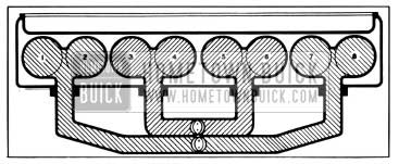
1950 Buick Fuel Distribution Through Intake Manifold
Intake Manifold Heat Control
The amount of heat supplied to the intake manifold below the carburetor is regulated in accordance with operating requirements by means of the exhaust manifold valve. The valve is controlled by a bi-metal thermostat wound around the valve shaft so as to act as a spring to close the valve when engine is cold. The inner end of the thermostat engages a slot in valve shaft and the hooked outer end engages an anchor stud on the valve body.
When the engine is cold, the valve is held in closed position by the thermostat. Hot exhaust gasses strike the valve and are deflected upward into the heat jacket on intake manifold, where they pass around the intake passages and then pass downward to the exhaust pipe. See figure 3-3.
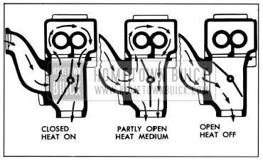
1950 Buick Exhaust Manifold Valve Operation-Sectional View
As the engine warms up, heat conducted to the thermostat through the valve shaft as well as by the increasing air temperature under the hood causes the thermostat to lose spring tension and allow the valve to move toward the open position, thereby reducing the amount of exhaust gas deflected into the heat jacket and consequently reducing the amount of heat to the intake manifold. See figure 3-3.
The exhaust manifold valve is offset or longer on the lower side of the shaft. This allows exhaust gas pressure to force the valve open when the engine is accelerated or operated with wide open throttle, thus reducing the heat to the intake manifold.
The valve is prevented from fluttering by a counterweight on the shaft. An anti-rattle spring is provided to prevent the valve from fluttering and rattling against the valve body’ in the open and closed position.
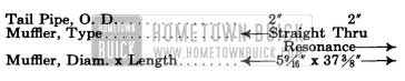
Exhaust Pipes, Muffler, and Tail Pipe
The muffler is a “straight through” type with resonance chambers which absorb and dampen out the exhaust sound waves. A slip joint at one end allows for expansion and contraction due to temperature changes. See figure 3-4.
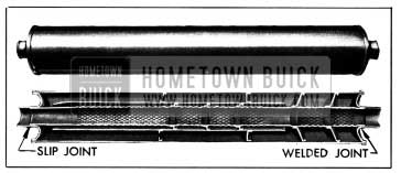
1950 Buick Muffler-Sectional View
The word “Front” is stamped on one end of the outer shell of muffler to indicate the end to place toward front of car during installation. The drain hole in outer shell should always be located at the bottom.
The exhaust pipe is connected to the exhaust manifold by a bolted flange and a gasket. The exhaust pipe and tail pipe connect to the muffler through slip joints provided with clamps. All exhaust system parts are flexibly mounted to allow for engine movement and for expansion and contraction due to temperature changes. All supports have fabric straps which provide the required flexibility and also serve to insulate exhaust system vibration from the chassis. See figure 3-5.
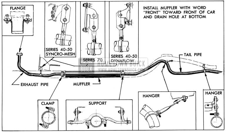
1950 Buick Exhaust System and Mountings
Leave A Comment
You must be logged in to post a comment.