SECTION 4-C 1950 BUICK DYNAFLOW TRANSMISSION
This section gives 1950 Buick Dynaflow procedures that are required in connection with work on other components of the car, also minor maintenance adjustments which can be performed without special training on the 1950 Buick Dynaflow transmission.
Complete service information on the 1950 Buick Dynaflow transmission is contained in the “1948-49-50 Dynaflow Transmission Shop Manual” (BPS 1.32). Refer to this Dynaflow manual for any information that is not covered in this Section.
4-15 1950 BUICK DYNAFLOW SPECIFICATIONS AND REFERENCES
Tightening Specifications
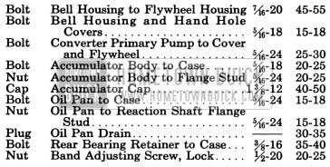
1950 Buick Dynaflow Transmission Tightening Specifications
Lubrication and Adjustments
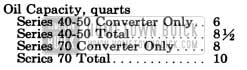
1950 Buick Dynaflow Lubrication and Adjustments
NOTE: A completely dry transmission requires 1 3/4, pints more than amounts given above.
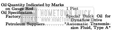
1950 Buick Dynaflow Lubrication and Adjustment
*Must be identified by AQ-ATF number embossed in can.
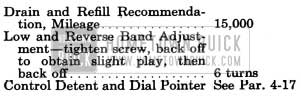
1950 Buick Dynaflow Lubrication
References to Other Sections
4-16 1950 BUICK DYNAFLOW MANUAL CONTROL MECHANISM, OPERATING INSTRUCTIONS, TROUBLE DIAGNOSIS
Manual Control Mechanism
1950 Buick Dynaflow Drive provides five different control or operating ranges which may be manually selected by the driver through movement of the shift control lever at top of steering column. A pointer on the control lever housing and a stationary dial mounted on steering column aid in locating the lever for each range. See figure 4-39.
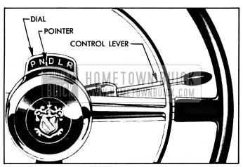
1950 Buick Dial and Pointer
Letters on the dial, reading from left to right identify each range as follows:
- P =Parking
- N =Neutral
- D =Direct Drive
- L=Low
- R =Reverse
It is necessary to raise the control lever against light spring pressure when shifting into Parking (P), Neutral (N) or Reverse (R). Raising the lever depresses a stop pin in the control lever housing so that the pin can pass the stops mounted in the dial housing. The stop pin and stops prevent accidental shifting into these ranges when car is in motion and also make it possible to quickly locate the control lever in any desired position without looking at the dial.
The control lever actuates a control shaft in steering column which is connected by levers and rods to a shift control valve in the transmission. A detent at lower end of the control shaft holds the manual control mechanism in the selected position.
The manual control mechanism also operates a neutral safety switch which is included in the cranking motor control circuit. The switch is closed so that the engine can be cranked only
when the control lever is in either the Neutral (N) or Parking (P) position, thereby preventing accidental movement of the car when the engine is started.
When the car is equipped with back up lights the manual control mechanism operates a back up light switch so that the circuit to the backup lamps is closed only when control lever is in Reverse position.
Parking (P) Range
Parking range is to be used in conjunction with the “step-on” parking brake to insure positive locking of car on steep grades. The shift control lever must be raised when shifting into or out of Parking position.
Parking range must never be entered when the car is in motion as serious damage to transmission will result.
For safety, Parking range should always be used when it is desirable to run and accelerate the engine without possibility of car movement, as when working on car in the shop.
When in Parking range, a parking lock ratchet wheel on transmission output shaft is engaged by a locking pawl mounted in the transmission rear bearing retainer, thereby providing a positive mechanical lock for the rear wheels. The locking pawl is actuated by the transmission manual control linkage through an apply spring which holds the pawl against the ratchet wheel until engagement of these parts is accomplished. If the pawl does not engage a notch in ratchet wheel when first applied it will snap into place as the wheel turns when car moves slightly.
The engine may be started while the car is locked in Parking position.
Neutral (N) Range
Neutral range as well as Parking range may be used when starting the engine. It is not necessary to shift into Neutral when the car is temporarily stopped with engine running during normal driving operation.
Neutral must always be used when towing the car with rear wheels on the road.
Neutral range may be used when it is desirable to run and accelerate the engine without possibility of car movement, but Parking range is recommended for this condition because of greater safety.
Direct Drive (D) Range
Direct Drive range is to be used for all forward driving conditions except as specified for low range.
Low (L) Range
Low range is used only when the engine is under an exceptionally heavy load, such as in deep snow or sand or on long steep grades. Low range can be used to obtain additional engine braking when descending steep grades.
The shifts between Low and Direct Drive ranges may be made while the car is in forward motion, but the D to L shift must never be made at speeds above 40 MPH.
Reverse (R) Range
Reverse range is used to move the car rearward. The shift control lever must be raised to shift into Reverse.
Rocking Car between Low and Reverse
When the car is stuck in deep snow or mud it can be driven out by “rocking” the car back and forth by alternately using Low and Reverse until sufficient momentum is obtained to move car out in desired direction.
After accelerating engine slightly to provide sufficient power, hold shift control lever up and move it back and forth between Low and Reverse. Control the engine speed and time the movement of control lever so that the rear wheels push firmly against the snow or mud in each direction but avoid spinning the rear wheels.
Pushing or Towing Car to Start Engine
If it becomes necessary to push a 1950 Buick Dynaflow Drive car to start the engine. place shift control lever in Neutral (N) until car speed reaches 15 MPH, then shift into Low (L). At this speed the rear oil pump develops sufficient pressure to apply the low band and the turbine is then turned fast enough to drive the primary pump and crank the engine. After engine starts, return control lever to Neutral (N) for engine warm up. It is safer to push car than tow it.
Towing Disabled 1950 Buick Dynaflow Drive Car
A disabled 1950 Buick Dynaflow Drive car must not be towed on rear wheels with transmission in any of the driving ranges because unnecessary damage to transmission may result. It may be safely towed in Neutral (N) only.
The Neutral Locking Strap should be employed to lock transmission in neutral position for towing in cases where car damage makes it impossible to obtain or maintain neutral position by means of the regular transmission control mechanism. Install the locking strap on transmission in the following manner.
- While holding shift lever forward to avoid straining internal linkage, remove lever retaining nut and lockwasher, then remove lever from cross shaft.
- Install neutral locking strap over cross shaft, with U-slot of strap straddling the speedometer cable sleeve nut. See figure 4-40. Hold strap in place by reinstalling shift lever.
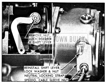
1950 Buick Installation of Neutral Locking Strap
Trouble Diagnosis
In case of improper transmission operation, check the following items. If these items do not correct the condition, refer to the Dynaflow Shop Manual for more extensive coverage of causes and corrections.
- Check Oil Level. In every case of improper operation check the oil level as prescribed in paragraph 1-1. If oil level is low bring it to proper level and check the results by road test. If oil level is very low, check rear axle oil level. An overfull rear axle indicates leakage between transmission and rear axle. If exterior of transmission is oily a thorough inspection for oil leakage should be made as described in the Dynaflow Shop Manual.
- Check Manual Control Linkage. In case of improper operation which is not eliminated by correction of oil level, check the adjustment of transmission manual control linkage as prescribed in paragraph 4-17.
- Adjust Low or Reverse Bands. If improper operation is evident in Low or Reverse but not in Direct Drive, adjust low or reverse band as prescribed in paragraph 4-18.
4-17 1950 BUICK DYNAFLOW MANUAL CONTROL LINKAGE ADJUSTMENTS
When a 1950 Buick Dynaflow transmission does not operate properly it is advisable to first check the manual control linkage to make sure it is correctly adjusted.
Before making any checks or adjustments on manual control linkage make certain that transmission is thoroughly warmed up and that oil is at proper level. To warm up transmission, drive car approximately 20 miles, with frequent stops and starts as might be encountered in heavy traffic.
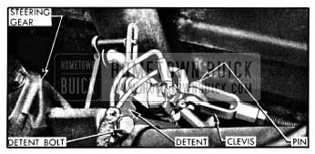
- Place shift control lever in Neutral (N) position so that detent plunger is centered in detent notch, then move control lever until stop pin is against stop in dial housing and note the movement of dial pointer.
- Repeat this operation in the low (L) position. The movement of dial pointer should be approximately equal in Neutral and Low. If it is not, loosen the control detent mounting bolts (fig. 4-41) and shift detent until movement of dial pointer is equal in both ranges. Tighten mounting bolts securely.
1950 Buick Shift Rod Adjustment
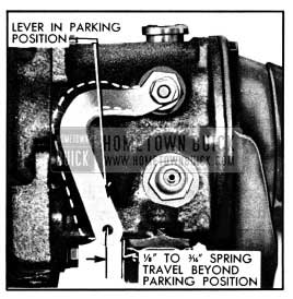
1950 Buick Spring Travel at Shift Lever
If spring travel is not within these limits the control valve operating rod in transmission is incorrectly adjusted and it will be necessary to remove the torque ball and adjust the operating rod as described in the Dynaflow Shop Manual.
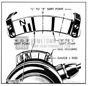
1950 Buick Linkage Adjustment Gauge J 3085 Set for Checking Shift Point
4-18 LOW AND REVERSE BAND ADJUSTMENTS
Chatter or slip in low or reverse may be due to improper band adjustment. A very slight chatter just as car starts to move in reverse, which disappears as soon as car is in motion, may be considered normal. Band adjustment should be made only if the chatter is severe enough to be objectionable.
Procedure for adjusting either Low or Reverse band is as follows:
- Remove front floor mat, insulation pad, and transmission opening pan from body floor pan.
- Remove band adjustment cover and gasket, using Removing Tool J 2655. See figure 4-44.
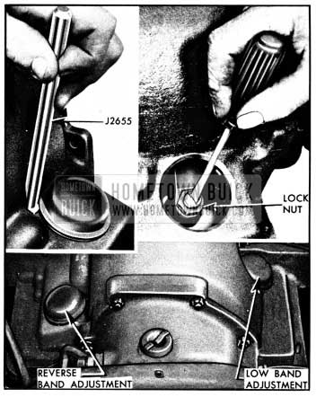
1950 Buick Band Adjustment
4-19 REMOVAL OF 1950 BUICK DYNAFLOW TRANSMISSION
- Raise right side of hood and remove bell housing dowel bolt located to rear of cranking motor solenoid, using a suitable offset brass drift. This bolt cannot be removed from under the car.
- Connect one wire of Remote Control Starter Switch J 2679 to the positive terminal of battery and connect other wire to the terminal of cranking motor solenoid switch relay to which a white wire with black parallel tracers is connected. Place starter switch so that engine can be cranked from under the car.
- Hoist front and rear of car and rest it solidly on stands placed under frame. Frame side rail should be at least 20″ above floor.
- Disconnect torque tube from torque ball and move rear axle back to disengage propeller shaft from universal joint.
- Remove bell housing cover and bell housing hand hole cover. See figure 4-45.
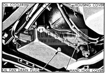
1950 Buick Right Side of Dynaflow Transmission Installation
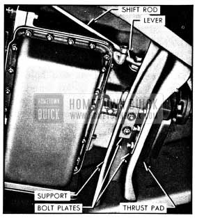
1950 Buick Left Side of Dynaflow Transmission Installation
4-20 INSTALLATION OF 1950 BUICK DYNAFLOW TRANSMISSION
- Turn flywheel so that one hole for converter drain plug is straight down and turn converter so that one drain plug is straight down. Paint marks placed on flywheel, converter primary pump and cover during removal must be in position to align when transmission is installed.
- Raise transmission into place with same equipment as used for removal. Align converter drain plug and cover bolts with corresponding holes in flywheel before moving transmission forward against flywheel housing.
- Adjust lifting equipment so that bell housing meets flywheel housing squarely, install the two bell housing dowel bolts first, then install remaining bell housing bolts and tighten to 45-55 ft. lbs. torque. The crankcase ventilator outlet pipe support is attached by the lower right bell housing bolt and the exhaust pipe hanger is attached by left hand bell housing bolts.
- Attach thrust pad to thrust plate. Raise transmission far enough to install transmission support then lower transmission until weight is carried by the mounting pad and support. Attach mounting pad to the support with bolt plate and self-locking nuts.
- Remove lifting equipment and engine support bar.
- With engine and transmission resting freely and normally on mounting, install sufficient shims between the thrust pad and the transmission support to fill the existing space. Insert shims from above with tabs on left side, then install the bolt plate and three nuts which attach thrust pad to the support.
- Connect converter to flywheel with paint marks on flywheel and primary pump aligned, and tighten bolts evenly to 25-30 ft. lbs. torque.
- Check converter drain plugs for tightness, then install bell housing and hand hole covers.
- Connect water hose from lower side of water pump to the lower connection of transmission oil cooler, and connect the other hose to upper connection of cooler. The upper hose runs from the car heater temperature control if heater is installed, or from the engine thermostat housing if heater is not installed.
- Connect speedometer cable and connect transmission shift rod to shift lever on transmission but leave front end disconnected for later adjustment.
- Cement a new gasket in recess in front end of torque tube and make sure that propeller shaft spline oil seal parts are installed on propeller shaft in the following order: Spring retainer, spring, seal cap, oil seal. See figure 5-3.
- Connect torque tube to torque ball with bolts and lockwashers.
- Place oil filler pipe spring bracket over filler pipe and connect pipe to oil pan pipe, with both pipes contacting inside the rubber connector hose. Place spring bracket over front end of bell housing dowel bolt. Nut and lockwasher will be installed later.
- Wipe all oil from outside of transmission then lower the car to floor.
- Install lockwasher and nut on right hand bell housing dowel bolt, making sure that oil filler pipe spring bracket is in place, that filler pipe is in line with oil pan pipe, and that clearance exists between filler pipe and floor pan.
- Fill transmission to proper level as described in paragraph 1-4. Fill radiator to proper level.
- Check adjustment of shift control detent, then adjust shift rod and connect it to shift idler lever as described in paragraph 4-17.
- Check adjustment of neutral safety switch (par. 10-34) and back up lamp switch (par. 11-3).
- Road test car for approximately 20 miles with frequent stops and starts as might be encountered in heavy traffic. A thorough road warm-up is desired.
- Place car on hoist and carefully examine the transmission and all connections for oil leaks. Recheck oil level.
Leave A Comment
You must be logged in to post a comment.