SECTION 2-G SERVICE ON 1950 BUICK ENGINE MOUNTINGS, FLYWHEEL AND HOUSING
2-31 1950 BUICK ENGINE MOUNTING ADJUSTMENT
The following procedure must be used to center the engine in the frame and adjust the 1950 Buick engine mountings and transmission mountings.
- Disconnect torque tube from torque ball.
- Tighten 1950 Buick engine mounting brackets to the crankcase and frame front X bar. Loosen the engine front mounting pad top stud nuts.
- Tighten transmission support to frame X member attaching bolts.
- Tighten transmission mounting pad to transmission support and to transmission rear bearing retainer.
- Tighten thrust pad to thrust plate stud nuts (rear) and loosen thrust pad to transmission support stud nuts (front). Remove shims between thrust pad and transmission support.
- Measure the distance between the front edge of crankshaft balancer, at horizontal centerline, and the center of the nearest shock absorber bolt head on each side. If distances on both sides are not equal, shift front of engine sidewise as required to center engine in frame, then tighten 1950 Buick engine mounting pad stud nuts securely. The mounting pad stud holes in engine mounting brackets are oversize to permit sidewise adjustment of engine.
- With engine and transmission resting freely and normally on mounting pads, install sufficient shims between the thrust pad and transmission support to snugly fill the existing space. Insert shims from above, with tabs on right side in Synchromesh cars or left side in Dynaflow Drive .cars. See figure 2-40.
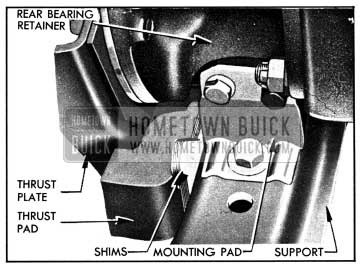
1950 Buick Transmission Mounting Pad, Thrust Pad and Shims
- Tighten thrust pad front stud nuts and tighten front engine mounting pad stud nuts.
- Connect torque tube to torque ball.
2-32 FLYWHEEL OR RING REPLACEMENT
The procedures in this paragraph apply only to the cast iron flywheel used with clutch and synchromesh transmission. For replacement of flywheel on Dynaflow engine refer to the 1948-49-50 Dynaflow Transmission Shop Manual.
Removal of Flywheel (synchromesh only)
Flywheel and ring assemblies are balanced separately from the crankshaft during manufacture; however, all completely assembled engines are given a running balance test in a special machine during production. In this test the flywheel is drilled, if necessary, to finally balance the entire engine to very close limits. For this reason, the flywheel and the crankshaft flange should be marked before flywheel is removed so that flywheel may be reinstalled in its original position on the crankshaft. It is also advisable to run the engine after the clutch is removed to note the degree of vibration with the original flywheel.
Flywheels are attached to the crankshaft with bolts, lockwashers and nuts. It is necessary to remove the crankshaft rear bearing cap and remove bolts from crankshaft in order to remove the flywheel. CAUTION: When turning crankshaft with rear bearing clip removed, hold the bearing inner oil seal to prevent it from moving out of the groove in crankcase.
Replacement of Flywheel Ring (synchromesh only)
To remove a flywheel ring from the flywheel, drill a 5/16″ hole in the ring between two teeth and split the ring at this point with a cold chisel.
The flywheel ring is a shrink fit on the flywheel and must be heated to approximately 600° F. in order to expand it sufficiently to go over the flywheel. Heating the ring in excess of 800° F. will destroy the effect of the heat treatment given during manufacture.
Excessive heating may be avoided by first polishing several spots on the ring with emery cloth, then heating the ring only until these spots begin to turn blue. Heat the ring to approximately 600° F. on a hot plate if available; otherwise, place ring on a sheet of metal or asbestos and heat it with a torch that is kept moving to secure even heating. When ring is at proper temperature, quickly place it over flywheel and allow the ring to cool slowly until it is tight in place.
Installation of Flywheel (synchromesh only)
If old flywheel is being reinstalled be sure to place it in original position on crankshaft flange in accordance with marks made before removal.
If a new flywheel or a new crankshaft is being installed, the flywheel bolt holes must be reamed to provide a very close fit for the bolts. Two bolt holes are reamed to size in replacement flywheels and crankshafts. Use these reamed holes to bolt the parts together, then ream the other holes and install bolts.
After installation of a new flywheel or a new flywheel ring, be sure to run the engine and check for vibration before installing the clutch. If engine has vibration that did not exist before installation of new parts, make correction as described under Correction of Engine Vibration (par. 2-34).
2-33 FLYWHEEL HOUSING ALIGNMENT
The procedures in this paragraph apply only to engines used with synchromesh transmission. For alignment of flywheel housing on Dynaflow engines refer to the 1948-49-50 Dynaflow Transmission Shop Manual.
The flywheel housing is attached to the cylinder crankcase with six 7/16″ bolts. Two 1/2″ straight dowel pins are installed in reamed holes in both parts to maintain alignment.
Misalignment between the pilot in rear face of housing and the pilot bearing in rear end of crankshaft may cause the transmission to be noisy or to slip out of high gear. To insure correct alignment in production, the pilot hole which receives the transmission main drive gear bearing is bored in the housing after it is assembled to the cylinder crankcase. The flywheel housing furnished for service is completely machined, but it must be checked for alignment after installation.
If an existing housing is suspected of being out of alignment it may be checked after removal of the transmission and clutch assemblies. If a new housing or cylinder crankcase is being installed, alignment should be checked before the flywheel, clutch and transmission are installed. When checking alignment the engine must be in an upright position, dowel pins must be installed, and all housing bolts must be tight.
Checking Alignment of Flywheel Housing (synchromesh only)
- Remove transmission (par. 4-13) and clutch (par. 4-5), leaving flywheel in place.
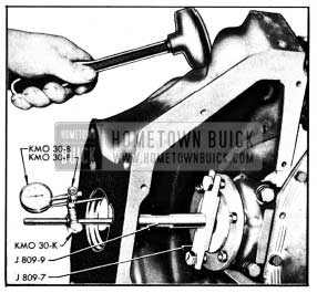
- Attach Strap J 808-7 and Pilot J 808-9 to flywheel with two flywheel bolts. Mount Dial Indicator KMO 30-B and Hole Attachment KMO 30-F on pilot with Sleeve KMO 30-K. Adjust ball end of hole attachment to bear against side of pilot hole in flywheel housing. See figure 2-41.
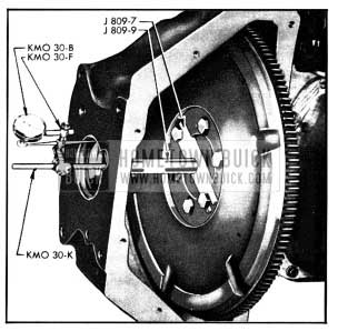
1950 Buick Checking Alignment of Flywheel Housing
- Turn flywheel very slowly and note total run-out of pilot hole as shown by dial indicator. If total indicator reading is .005″ or less, flywheel housing alignment is satisfactory. If runout exceeds .005″, correction must be made as described in subparagraph b, below.
Correction of Flywheel Housing Misalignment (synchromesh only)
- Remove flywheel (par. 2-32), housing, and dowel pins. Reinstall crankshaft rear bearing cap.
- Drill out the two upper bolt holes in flywheel housing and the four bolt holes in crankcase flange with a 1/2″drill. See figure 2-42 and 2-43.
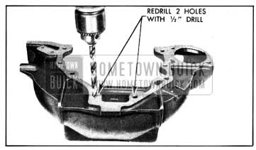
1950 Buick Enlarging Bolt Holes in Housing
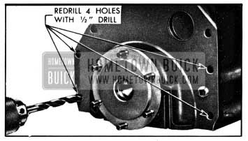
1950 Buick Enlarging Bolt Holes in Crankcase Flange
- Install flywheel housing without dowel pins, and leave bolts just loose enough to permit shifting of housing by tapping with lead hammer. NOTE: Use sealing compound on flywheel housing upper bolt on camshaft side to prevent oil leaking into flywheel housing.
- Install dial indicator as shown in figure 2-44 and check run-out at pilot hole in housing.
1950 Buick Aligning Housing
- Shift housing by tapping with lead hammer as required to bring run-out at pilot hole within .002″ indicator reading. Tighten housing bolts and re-check run-out.
- Using Special Reamer J 808-4 and Ratchet Wrench J 808-6, ream the dowel holes and install two oversize dowel pins J 808-5. See figure 2-45.
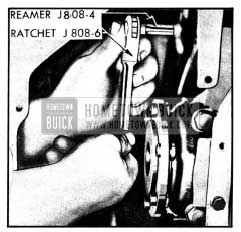
1950 Buick Reaming Dowel Pin Holes
- Mount dial indicator on crankshaft flange and set to bear against rear face of flywheel housing at a radius of 2 1/2″.
- Turn crankshaft and note run-out of housing rear face, making sure that end thrust of crankshaft is all one way while making this check. If total indicator reading exceeds .003″, shellac paper shims of proper thickness in position required to give an indicator reading of .003″ or less.
- Install flywheel, clutch (par. 4-5), and transmission (par. 4-13).
2-34 CORRECTION OF UNBALANCED ENGINE
The procedures in this paragraph apply only to engines used with synchromesh transmissions. For correction of unbalance in Dynaflow transmission and engine refer to the 1948-49-50 Dynaflow Transmission Shop Manual.
An extremely unbalanced engine should always be corrected by replacing parts which are abnormally out of balance or materially different in weight from corresponding parts. The procedure described here is intended only for corrections of minor cases of unbalance which may occur where individually balanced parts are assembled together.
If the vibration developed after removal and installation of clutch assembly, check all clutch cover bolts to make sure they are of same length and that each has one lock washer. Also check marks that were made when clutch was removed and disassembled to make sure that clutch was assembled and installed according to these marks. Make any corrections indicated by this inspection and run engine at the critical speed to check results.
If clutch assembly and installation does not appear to be at fault, mark clutch cover and flywheel and remove clutch assembly (par. 4-5). Run engine at critical speed and check for vibration. If vibration is eliminated, the clutch is at fault and should be balanced as described below. If vibration still exists, however, it will be necessary to balance the flywheel on the crankshaft.
To balance the flywheel, insert one clutch cover bolt successively in each hole in flywheel and check results at each position by running the engine. It may be necessary to vary the test weight by adding washers or by using a shorter
bolt. When a proper weight and position has been found to eliminate the vibration, the bolt will be on the light side of flywheel. Remove the bolt and drill shallow holes in diametrically opposite side of flywheel, until enough weight has been removed to make engine run smooth. Use a 3/8″ drill and do not drill any hole more than 1/4″ deep.
Install clutch assembly according to marks (par. 4-5) after making sure that engine runs smooth with clutch removed, and again check for vibration at the critical speed. If vibration exists with clutch installed, install one plain washer under the lock washer of each clutch cover bolt in turn until a location is found where the engine runs smooth. It may be necessary to place plain washers on two adjacent bolts in order to obtain enough weight at the proper location to secure balance.
Leave A Comment
You must be logged in to post a comment.