SECTION 10-G 1950 BUICK LIGHTS – LIGHTING SYSTEM
10-53 1950 BUICK LIGHTING SWITCH AND CIRCUIT BREAKER
Description of 1950 Buick Lighting Switch
The first Series 1,.0 cars use a lighting switch which does not control the map and instrument panel lights; these lights are controlled by separate switches. Later Series 40 and all Series 50-70 cars use a lighting switch which incorporates a manually operated rheostat for controlling the map and instrument panel lights, thereby eliminating the separate switches for these lights.
Both lighting switches are “push-pull” types operated by a knob marked “LIGHTS”. Three “push-pull” positions of the switch knob provide control of the lights as follows:
- “Off” position (knob all the way in) cuts off all 1950 Buick lights controlled by the switch.
- “Parking” position (knob pulled out to first notch) turns on the parking lights, tail lights, and license light. The map and instrument panel lights also will be turned on if the controlling switch (1st Ser. 40) or rheostat is set for these lights.
- “Driving” position (knob pulled out to last notch) turns parking lights off and turns headlights on, while the other lights remain as in the “Parking” position. The headlights will be on the “upper” or “lower” beams depending on the position of the separate dimmer switch.
The knob of the Series 40-50-70 lighting switch must be rotated “to control the map and instrument panel lights. With knob turned all the way counterclockwise these lights are off. Turning the knob clockwise the first step turns on the map lights only, the second step turns on the instrument lights and leaves map lights on, the third step turns map lights off and leaves the instrument lights on; further turning of knob clockwise reduces the brilliance of instrument panel lights.
Description of 1950 Buick Thermo Circuit Breaker
A thermo circuit breaker is incorporated in the lighting switch assembly, to protect wiring from damage due to short circuits in any lighting circuit controlled by the switch.
The thermo circuit breaker consists of a bimetal blade and set of contact points connected in series with the lighting circuits. An abnormal flow of current through the circuit breaker, such as would be caused by a short circuit in a lighting circuit, heats the bi-metal blade sufficiently to separate the points and cause them to vibrate. The vibrating blade alternately opens and closes the circuit, thus reducing the flow of current and protecting the wiring against overheating and burning. The flickering light produced by the vibrating circuit breaker serves as a warning to the operator of vehicle that a short circuit exists.
Test of 1950 Buick Lighting Switch
If the lighting switch is suspected of being faulty, the contacts can be tested by connecting a short jumper wire between No.1 terminal and the other terminals while observing any change in the brilliance of lights affected.
With switch in “Parking” position (first notch out) connect jumper wire between No. 1 and No. 2 terminals and note change in parking lights. Bridge between No. 1 and No.3 terminals and note change in tail lights. With switch in “Driving” position (last notch out) bridge between No. 1 and No. 4 terminals and note change in headlights.
If no change in brilliance of 1950 Buick lights is noted the switch contacts are satisfactory and the cause is in the wiring circuit connections or lamp bulb. If switch is faulty it must be replaced since internal repairs cannot be made.
Replacement of 1950 Buick Lighting Switch
- Disconnect ground cable from battery and disconnect wires from lighting switch.
- Loosen knob retaining set screw with a 3/32″ Allen wrench and remove knob from rod. Remove switch mounting nut with Wrench J 1589 and remove switch from panel. See figure 10-81.
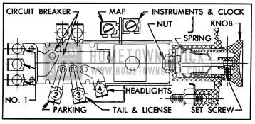
1950 Buick Lighting Switch-Series 40-50-70
- On first Series 40 switch, control rod may be removed by depressing the retaining spring. On the Series 40-50-70 switch, pull rod out as far as possible, insert stiff wire into small hole in switch case to depress the catch and pull rod out. NOTE: Knob and rod may be removed as a unit in this manner before removal of switch.
- When installing lighting switch, connect wires according to color codes as shown on chassis wiring circuit diagrams in Section 10-J. When connecting battery ground cable use care to properly wind the clock (par. 10-21, e).
Test of 1950 Buick Thermo Circuit Breaker
To test the thermo circuit breaker, remove lighting switch from instrument panel to avoid possible damage to adjacent instruments.
Since the current required to open the circuit breaker contacts depends somewhat on outside temperature, the circuit breaker should be tested at normal temperature (70° to 80°F.).
- Connect an ammeter and a carbon-pile rheostat in series with the No. 1 terminal of lighting switch and positive terminal of a 6- volt battery, and set rheostat to provide maximum resistance. Rheostat must have capacity for 42 amperes and be adjustable down to .14 ohms.
- Connect the protected (not numbered) terminal of lighting switch to negative post of battery.
- Adjust rheostat to give 42 amperes. The circuit breaker should start vibrating in three minutes or less.
- Adjust rheostat to give 30 amperes on ammeter. The circuit breaker should remain closed indefinitely at 30 amperes.
- If circuit breaker does not operate as specified the lighting switch assembly should be replaced. The circuit breaker is not adjustable and no attempt should be made to alter the calibration by bending the bi-metal blade. The contact points must not be filed or sanded.
10-54 1950 BUICK HEADLIGHTS AND CONTROLS
1950 Buick Headlamp Assembly
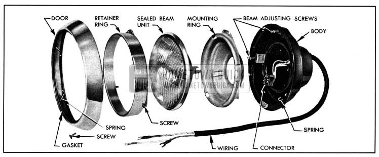
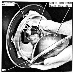
The headlamp assembly on each front fender consists of a body, wiring, connector, mounting ring, sealed beam unit, retainer ring, door and gasket. See figure 10-82.
1950 Buick Headlamp Disassembled
The headlamp body is attached to the fender with a gasket between body and fender to provide a water-tight seal. The wiring to which the connector is attached extends through rear of lamp body and connects to a terminal block on the radiator baffle. The mounting ring, which supports the sealed beam unit, forms a ball and socket joint with the body, to which it is attached by one coil spring and two beam adjusting screws. The sealed beam unit is attached to the wiring connector and is held in the mounting ring by the retaining ring which is attached to mounting ring by three screws. The headlamp door surrounds the retaining ring and is attached to the body by a lug at the top and one screw at bottom of door. A rubber gasket, held in the door by W-shaped retaining springs, form a seal between door and retainer ring. See figure 10-82.
1950 Buick Sealed Beam Unit and Headlight Beams
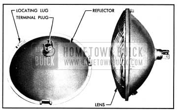
The sealed beam unit consists of a lens, reflector, terminal plug, and two lamp filaments assembled into one securely sealed unit. See figure 10-83.
1950 Buick Headlamp Sealed Beam Unit
The lamp filaments are located with respect to the reflector so that two separate and distinct headlight beams may be obtained, depending upon which filament is burning.
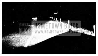
When the lower lamp filament is burning, an upper or straight forward light beam is obtained. The upper beam is designed to illuminate the road evenly, and is for use on the highway when no other vehicles are approaching. See figure 10-84.
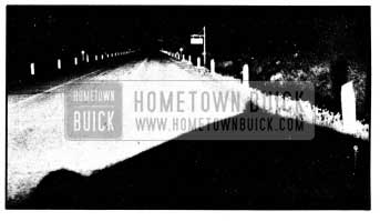
1950 Buick Light Distribution with Upper Headlight Beam
When the upper lamp filament is burning, a lower or depressed light beam is obtained. The lower beam is designed so that it does not throw a dazzling light into the eyes of an approaching driver. At the same time, the distribution of light is such that the right side of road is illuminated as far ahead as is practicable without causing glare on curves. See figure 10-85.
1950 Buick Light Distribution with Lower Headlight Beam
The lower beam is intended for use in traffic and on the highway when meeting other vehicles.
1950 Buick Dimmer Switch
The driver may select the upper or lower headlight beam as traffic and road conditions demand by operating the dimmer switch mounted on the toe panel in a convenient position for the left foot.
The dimmer switch opens and closes the circuits to the upper and lower lamp filaments in both sealed beam units, thereby alternately raising and lowering the headlight beams with each sucessive operation of the switch. Depression of switch button turns the rotary contacts one position within the switch. The spring-loaded button automatically returns to the reset position when released. The switch contacts overlap so that the new circuit is closed before the previous one is opened, in order to prevent both beams being off at the same time during operation of the switch.
1950 Buick Headlight Beam Indicator
Whenever the upper headlight beams are lighted, a beam indicator bulb on the instrument panel also lights, producing a small spot of red light at the top of the speedometer between the words “Bright Lights.” This indicator warns the driver that the upper beams are lighted. For safety reasons, he should never pass an approaching car with the beam indicator showing red.
10-55 1950 BUICK HEADLAMP SEALED BEAM UNIT REPLACEMENT AND ADJUSTMENT
Replacement of 1950 Buick Sealed Beam Unit
When a sealed beam unit is burned out or broken it must be replaced as a unit assembly. Two types of sealed beam units are available. In one type, the glass lens and a glass reflector are fused together. In the other type, the glass lens and a metal reflector are assembled together with a gasket to provide a tight seal. Both types are interchangeable. See figure 10-83.
- Remove screw at bottom of headlamp door, swing door outward at bottom and lift up to remove.
- Remove the three retainer ring screws but do not disturb the two beam adjusting screws, then remove retainer ring. See figure 10-86.
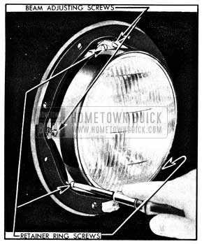
1950 Buick Removal of Sealed Beam Unit Retainer Ring
- Remove sealed beam unit from mounting ring and separate it from the wiring connector.
- Install new sealed beam unit by reversing removal procedure. The lens is marked “TOP” and the reflector has three lugs which fit into notches in the headlamp mounting ring. See figure 10-87.
1950 Buick Installation of Headlamp Sealed Beam Unit
Before installation of headlamp door, adjust headlamp for proper aim as described below.
1950 Buick Headlamp Aiming Adjustment
The headlamps must be properly aimed in order to obtain the maximum road illumination and safety that has been built into the head lighting equipment. The headlamps must be checked for proper aim whenever a sealed beam unit is replaced and after any adjustment or repairs of the front end sheet metal assembly.
Headlamp aiming machines are in general use.
When using one of these machines make certain that it is in proper condition, and carefully follow the instructions of the manufacturer. Headlamp aiming charts are also available and will give good results if used properly; see subparagraph c below.
Regardless of method used for checking headlamp aim, car must be at curb weight, that is, with gas, oil, water, and spare tire, but no passengers. Tires must be uniformly inflated to specified pressure (par. 6-8). If car will regularly carry an unusual load in rear compartment, or a trailer, these loads should be on car when headlamps are checked. Some states have special requirements for headlamp aiming adjustment and these requirements should be known and observed.
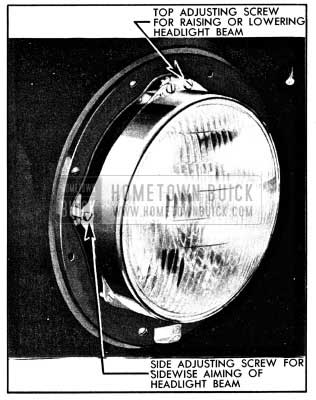
Horizontal and vertical aiming of the headlamp beam is provided by the two beam adjusting screws which move the mounting ring in the body against the tension of the coil spring. There is no adjustment for focus since the sealed beam unit is set for proper focus during manufacturing assembly. If headlamps require adjustment for proper aim, proceed as follows:
- Remove screw at bottom of headlamp door, swing door outward at bottom and lift up to remove.
- Adjust light beam up or down as required by turning the top beam adjusting screw. See figure 10-88.
1950 Buick Headlamp Aiming Adjustments
- Adjust light beam to right or left as required by turning the side beam adjusting screw.
- Check final setting of headlamps after installing headlamp doors.
Use of 1950 Buick Headlamp Aiming Chart
If a headlamp aiming machine is not available a chart may be prepared as shown in figure 10-89.
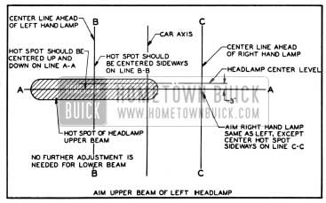
1950 Buick Headlamp Aiming Chart
It is desirable to make the chart on a large panel of plywood or other suitable material, painted flat white, so that it can be shifted into proper alignment with car, as explained later. Note that the chart consists of two horizontal and three vertical lines. The upper horizontal line is located at the same distance from floor as the center of headlamps and the lower horizontal line (A-A) is 3″ below the headlamp center line. Where State laws require a loading allowance be governed by these requirements for the lower line. Vertical lines B-B and C-C are located at the center of head lamps and equally distant from the center vertical line which corresponds to axis of car.
When using the headlamp aiming chart, place car on a level stretch with chart placed 25 feet ahead of both headlamp lenses, . and parallel to them. Place a narrow piece of masking tape on the exact vertical centerline of the back window glass. Shift chart sideways as required to bring the center vertical line into exact alignment with the center of radiator ornament and center of the back window glass.
Set lighting switch in “driving” position and operate dimmer switch to give upper beam.
Cover right headlamp and note light pattern made on chart by the left headlamp. The center of zone of highest light intensity should fall on the intersection of horizontal line A-A and the vertical line B-B as shown in figure 10-89. Cover left headlamp and check right headlamp in the same manner.
10-56 1950 BUICK PARKING, SIGNAL, TAIL, STOP, AND LICENSE LAMPS
1950 Buick Front Parking and Signal Lamps
The small lamps mounted in the front bumper guards are combination parking and direction signal lamps. Each lamp contains one 21-3 CP lamp bulb which may be replaced by removing the lamp door. The pins on bulb and slots in of 21 CP and 3 CP filaments when installing a new bulb.
When the lighting switch is in the “Parking” position (first notch out) the 3 CP filament in each lamp burns. This circuit is protected by the thermo circuit breaker on the lighting switch.
When the direction signal switch is operated, the 21 CP filament flashes on and off in the lamp on the side of the car for which a turn is indicated. This circuit is independent of the lighting switch and is protected by a fuse mounted on fuse block under the cowl.
1950 Buick Tail, Stop, and Signal Lamps
A combination tail, stop, and signal lamp is mounted on each rear fender. Each lamp contains a 21-3 CP stop and tail lamp bulb and a separate 21 CP direction signal lamp bulb. When car is not equipped with direction signals the 21 CP bulb and socket are omitted from the assembly.
When lighting switch is in either the “Parking” or “Driving” position the 3 CP filament in both lamp bulbs burn to provide taillights. When the brakes are applied, the 21 CP filament in both lamp bulbs burn to provide stop lights regardless of position of lighting switch.
When the direction signal switch is operated, the separate 21 CP lamp bulb flashes on and off on the side of car for which a turn is indicated; the bulb in lamp on opposite side of car does not light.
The taillight circuit is protected by the thermo circuit breaker on the lighting switch. The stop and direction signal light circuits are protected by the direction signal fuse on the fuse block under the cowl.
Lamp bulbs may be replaced by removing the tail lamp door which is retained by two screws. The pins on the 21-3 CP bulb and slots in socket are offset to prevent reversing position of 21 CP and 3 CP filaments when installing a new bulb.
When installing a lens be sure that drain notch is at the bottom; top of lens is marked “TOP.” When reinstalling lamp door be sure that gasket is in proper position to seal door. See figure 10-90.
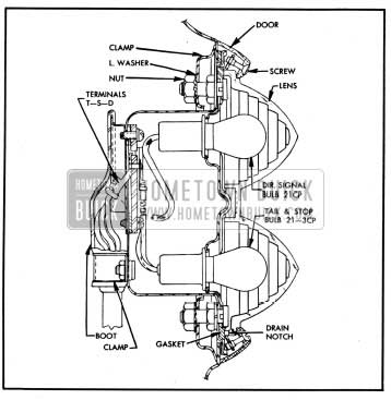
1950 Buick Tail, Stop, and Signal Lamp
Each lamp assembly is attached to the fender by a clamp and two nuts with external-tooth lockwashers. The wires are connected to three terminals on lamp body marked “T”, “S”, and “D” which are self-explanatory. These terminals are protected by a boot which snaps over a flange on lamp body and is further retained by a clamp. See figure 10-90.
1950 Buick Rear License Lamp
The rear license lamp is mounted in a protected position in the rear bumper guard upper rail, above the license plate. It contains one 3 CP lamp bulb which operates in conjunction with the tail lights and the circuit is protected by the circuit breaker on lighting switch. To replace lamp bulb, remove two coin slotted sleeve nuts which attach the lamp socket and wire assembly.
10-57 1950 BUICK INTERIOR LIGHTS AND 1950 BUICK CIGAR LIGHTERS
1950 Buick Instrument Panel Lights and Switches
The speedometer and gauges are illuminated by four 2 CP lamp bulbs, and the clock is illuminated by one 2 CP lamp bulb. These bulbs are mounted on forward side of instrument panel to provide indirect lighting. The instrument panel light circuits are protected by the thermo circuit breaker on lighting switch.
On later Series 40 and all Series 50-70, the instrument panel lights are controlled by the lighting switch as described in paragraph 10-53. On first Series 40 the instrument panel lights are controlled by a separate “push-pull” type switch having four positions as follows:
- Off – Knob pushed all the way in
- Bright – Knob pulled out one notch
- Medium – Knob pulled out two notches
- Dim – Knob pulled to last notch
A fuse located on the first Series 40 instrument panel light switch protects the switch, instrument and clock light circuits. The fuse can be replaced without removing the switch. The upper terminal on switch is the hot or live terminal. The lower terminal feeds the instrument and clock lights.
The Series 40 instrument panel light switch can be removed from the radio grille by removing the knob and the mounting nut. Loosen set screw on underneath side of knob, using a 3/32″ Allen wrench, then pull knob out. Use Wrench J 1589 to remove switch mounting nut, then remove switch and disconnect wires.
1950 Buick Map Lights and Switch
On later Series 40 and all Series 50-70, two map lights are located in the radio speaker grille adjacent to the ash trays. Each map light consists of a 2 CP lamp bulb mounted on forward side of the grille in position to project light downward through an opening in grille. Both lights are controlled by the lighting switch as described in paragraph 10-53.
To replace the bulb in a Series 40-50-70 map light remove the adjacent ash tray to obtain access to the bulb holder. Place a small screwdriver behind the tab of bulb holder and move holder toward center of ash tray opening until it snaps into the full “out” position. After replacing the bulb, slightly press in on bulb holder and push it back into position, then install ash tray.
On first Series 40, a map light and switch assembly is mounted in the lower left corner of the radio speaker grille. The switch makes contact to turn on the light when the “map light” knob is pulled out. The map light circuit is protected by the thermo circuit breaker on the lighting switch.
The switch knob may be removed for replacement of lamp bulb by firmly pulling it farther out from the “light on” position. When the knob is installed, align the key on knob with the slot in knob sleeve. The switch assembly is attached by a special nut which may be removed with Wrench J 1588, after removal of switch knob. See figure 10-91.
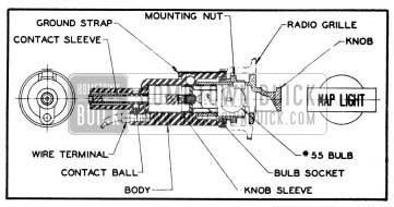
1950 Buick Map Light Switch-First Series 40
1950 Buick Instrument Panel Compartment Light
The instrument panel compartment (glove box) is lighted by a 2 CP lamp bulb mounted in a light switch attached to top edge of the compartment. The spring-loaded switch makes contact when the compartment door is opened. As the door is closed it depresses the switch button to break contact and turn the light off. This circuit is protected by the 30 ampere “Dome” fuse on the fuse block under cowl.
1950 Buick Dome Lamp and Switches
The dome lamp is controlled by a manual switch on the left side of body. The dome light is also controlled by spring-loaded jamb switches on both front and rear door hinge pillars. The jamb switch automatically turns dome light on when door is opened.
The dome lamp wiring is protected by a 30 ampere fuse, marked “Dome,” on the fuse block under the cowl. Dome lamp wiring circuit diagrams are given in Section 10-J.
1950 Buick Luggage Compartment Light
The luggage compartment lamp is mounted on the rear compartment lid and contains a 2 CP lamp bulb. A switch built into the lamp assembly automatically turns the light on when rear compartment lid is raised, and turns light off when lid is lowered. The luggage compartment lamp is connected to the dome light circuit so that it is protected by the 30 ampere “Dome” fuse on the fuse block under cowl.
1950 Buick Cigar Lighters
Two different cigar lighters are used, which are different in design so that the parts are not interchangeable. In figure 10-92 the Rochester Products lighter is shown in view A and the Casco lighter is shown in view B.
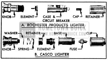
1950 Buick Cigar Lighters
Both type lighters are heated by pressing the knob in until it latches; the knob will automatically unlatch and return to “off” position when heated to proper temperature.
In the Casco lighter, a replaceable thermal fuse located in the lighter base protects the lighter element against overheating if knob is manually held in for too long a period. In the Rochester Products lighter, a circuit breaker located in the case provides protection against overload and overheating. See figure 10-92.
The Rochester lighter circuit breaker can be easily reset after it has opened the circuit due to an overload. Disconnect the bayonet type wire connector, remove insulating cap from end of circuit breaker and push the circuit breaker plunger in until it is engaged. Reinstall insulating cap firmly on lighter case and connect the wire.
Leave A Comment
You must be logged in to post a comment.