SECTION 4-B 1950 BUICK SYNCHROMESH TRANSMISSION AND UNIVERSAL JOINT
4-7 1950 BUICK SYNCHROMESH TRANSMISSION AND UNIVERSAL JOINT SPECFICATIONS
1950 Buick Synchromesh Transmission Tightening Specifications
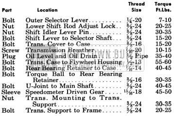
1950 Buick Synchromesh Transmission Tightening Specifications
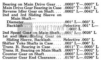
1950 Buick Synchromesh Transmission Specifications
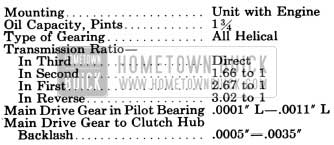
1950 Buick Synchromesh Transmission Specifications
1950 Buick Synchromesh Transmission Specification
NOTE: Where dimensions and limits for fit of parts are given in these specifications they apply to new parts only. Where limits are given, “T” means tight and “L” means loose.
Universal Joint and Torque Ball
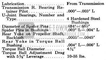
1950 Buick Universal Joint and Torque Ball Specifications
Speedometer Gears
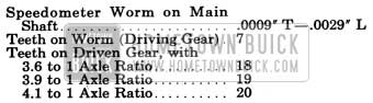
1950 Buick Speedometer Gears
4-8 DESCRIPTION OF 1950 BUICK SYNCHROMESH TRANSMISSION AND UNIVERSAL JOINT
The 1950 Buick Synchromesh transmission is standard equipment and Dynaflow Drive is available as optional equipment on Series 40-50. On Series 70, Dynaflow Drive is standard equipment and the 1950 Buick Synchromesh transmission is not available.
1950 Buick Synchromesh Transmission Mounting
The 1950 Buick Synchromesh transmission is solidly bolted to the rear face of flywheel upper housing, with a heavy paper gasket between, to form a unit assembly with the engine. The transmission main drive gear extends through the clutch driven plate into a single-row-ball pilot bearing seated in the rear end of engine crankshaft. The outer race of main drive gear bearing projects from transmission case to seat in a counterbore in flywheel housing, thus serving as a pilot to center the transmission with engine crankshaft.
The transmission, as well as rear end of engine, is carried on a channel-shaped support or cross member which is bolted to the frame “X” member. The transmission is cushioned on a rubber mounting pad which is bolted to the rear bearing retainer and to the top of transmission support. Driving thrust is taken by a rubber thrust pad located between the rear flange of transmission support and a thrust plate attached to rear bearing retainer by the torque ball retainer bolts. Shims, as required, are placed between the transmission support and the thrust pad to fill any fore and aft space existing at this point when engine and transmission mounting pads are in normal position. See figure 4-28.
1950 Buick Synchromesh Transmission Construction
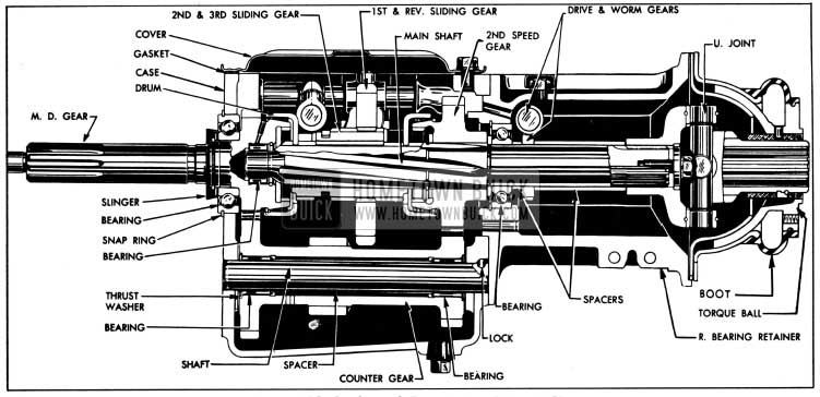
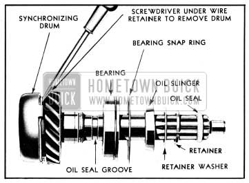
The 1950 Buick Synchromesh transmission main drive gear is supported by a ball bearing seated in front wall of transmission case. The ball bearing, which is shielded on rearward side, is pressed against a shoulder on main drive gear and held in place by an oil slinger, washer. and retainer (snap ring). The outer race of bearing is grooved for a snap ring which fits between transmission case and flywheel housing to hold bearing and main drive gear in place. See figure 4-13.
1950 Buick Synchromesh Transmission-Series 40-50
The front end of transmission main shaft is piloted in the bored rear end of main drive gear by a bearing consisting of 14 small steel rollers, which are retained in drive gear by a washer and snap ring. The main shaft is also supported by the transmission rear bearing which seats in transmission rear bearing retainer. The outer race of rear bearing is held in position by a shoulder in bearing retainer and a lock (snap ring) which engages a groove in retainer. The inner race of bearing is clamped against the main shaft thrust washer by a short spacer, speedometer worm gear, long spacer and universal joint. See figure 4-13.
The 1950 Buick Synchromesh transmission counter gear is supported by two roller bearings on a shaft which is held stationary in transmission case by a steel ball seated in recesses in case and rear end of shaft.
A tubular spacer and two thrust washers are located between the roller bearings, and a retaining washer is located at outer end of each bearing to hold the rollers in position. End thrust is taken by a bronze thrust washer at each end of counter gear. A hole in hub of counter gear permits lubricant to reach bearings and thrust washers. See figure 4-13.
The reverse idler gear is provided with two bronze bushings and is supported on a shaft which is held stationary by a grooved pin lock driven into holes in transmission case and rear end of shaft. End thrust is taken by a bronze thrust washer at each end of idler gear. Lubricant is fed to thrust washers and bushings through passages in transmission case and a groove cut through the bore of idler gear.
The second speed gear is mounted on the main shaft between two thrust washers and a snap ring, which hold it in position to mesh with the counter gear. It is free to rotate on the main shaft except when engaged by the second and third speed sliding sleeve during second speed operation. The sliding sleeve is splined to the main shaft to transmit drive when sleeve is engaged with either the main drive gear (third speed) or the second speed gear. The sliding
sleeve carries the first and reverse sliding gear on splines so that it also transmits drive to the main shaft in first speed and reverse. See figure 4-13.
Shift Mechanism in 1950 Buick Synchromesh Transmission
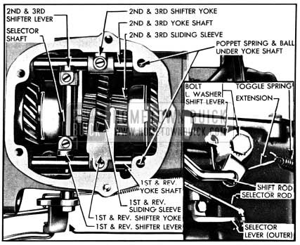
The first and reverse sliding gear is moved forward or rearward from the neutral position by a shifter yoke mounted on a shaft supported in left side of transmission case. The second and third speed sliding sleeve is similarly actuated by a yoke and shaft on right side of case. Each shifter yoke shaft is notched for engagement by one of two shifter levers mounted on a selector shaft which is supported in transmission case at right angle to yoke shaft. The levers are located on selector shaft so that only one lever at a time can engage its yoke shaft. See figure 4-14.
1950 Buick Shift Mechanism in Transmission
Engagement of a shifter lever with its yoke shaft, to select a gear shift, is obtained by moving selector shaft to right or left as required. This transverse movement of selector shaft is made by a selector lever and shaft which engages a groove in selector shaft. The selector lever shaft extends through transmission case and has a lever on its outer end which is actuated by a selector rod connected to the selector control mechanism in steering column. See figure 4-14.
Forward or rearward movement of the selected shifter yoke shaft, to complete the gear shift, is obtained by rotating the selector shaft. This movement is made by a shift lever mounted on outer left end of shaft and actuated by a shift rod connected to the gear shift control mechanism in steering column. A toggle spring and extension attached to shift lever aids in moving the sliding parts. See figure 4-14. A spring loaded poppet ball, housed in a recess in transmission case under each yoke shaft, engages one of three recesses in shaft to hold the shaft in desired position.
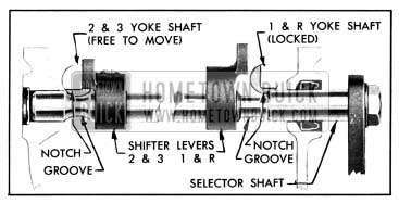
An interlock arrangement permits movement of one shifter yoke and shaft only when the opposite yoke shaft is locked in neutral position. The full diameter of selector shaft engages a notch in one yoke shaft to lock it while the opposite yoke shaft is free to move through a groove in the selector shaft. See figure 4-15.
1950 Buick Transmission Shift Interlock
A seal pressed into a recess in transmission case prevents leakage of oil around the extended left end of selector shaft. A welsh plug closes the opening in case at right end of shaft. A cork seal, spring washer, and plain washer prevents leakage of oil around the selector lever shaft. See figure 4-17.
Gear Synchronization
Transmission gears are synchronized only when shifting into second and third speeds. When the transmission is shifted into second or third speed, the sliding sleeve and the gear it engages are synchronized in speed through the action of a synchronizing drum. Each drum is a steel stamping having a bronze insert machined to match a conical surface on the gear, to which drum is loosely attached by a wire retainer. Synchronization is obtained when the beveled cam surfaces of the two slots in sliding sleeve come in contact with the beveled cam surfaces on the two fingers of synchronizing drum. See figure 4-16.
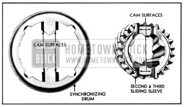
1950 Buick Cam Surfaces on Drum and Sleeve
This contact of cam surfaces presses the drum against the gear so that gear is brought to the same speed as the sliding sleeve, and the slight angular motion imparted permits the teeth of sliding sleeve and gear to mesh quietly and easily.
Universal Joint and Torque Ball
The universal joint is splined to the rear end of transmission main shaft and retained by a heavy steel washer and bolt. It is entirely enclosed by the transmission rear bearing retainer and by the torque ball and retainers which are attached to rear end of the bearing retainer.
The universal joint yokes are provided with hardened and ground steel bushings, held by retainer rings, which provide bearings for the hardened and ground pins of the universal joint cross. The rear yoke is splined internally to engage the propeller shaft, and is ground externally to provide a bearing in a bronze bushing in the torque ball. See figure 4-13.
The torque ball is supported between an inner and outer retainer which are centrally located and bolted to the transmission rear bearing retainer. The retainers are copper plated and the bearing surfaces of the torque ball are also plated to prevent scoring during break-in.
The universal joint, torque ball, and speedometer drive gears are automatically lubricated from the transmission. Oil enters the rear bearing :retainer through a hole at the top and returns to transmission through a hole at bottom of retainer. A synthetic rubber boot extends from the outer retainer to the flange of torque ball to provide an external oil seal and an oil seal installed in torque ball at rear end of bronze bushing prevents leakage of oil between transmission and torque tube. A breather or air vent is installed in upper side of the rear bearing retainer to prevent a buildup of pressure, due to heat, that would force transmission lubricant out past gaskets and oil seals. See figure 4-13.
Speedometer Gears
The speedometer worm gear (driving gear) is mounted on transmission main shaft and held in place by the universal joint and spacers. The same worm gear is used in all series for all rear axle gear ratios. In changing axle ratios it is only necessary to change the driven gear.
The speedometer driven gear is furnished only as an assembly consisting of sleeve, shaft, retaining washer and gear. See figure 4-17.
1950 Buick Speedometer Driven Gear Assembly
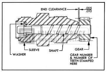
The number of teeth and a part number are stamped on the side of gear; however, the part number is that of the gear only and is not the number of the driven gear assembly as listed in the Master Parts List.
To insure proper mating of drive and driven gears as well as correct speedometer readings when making a replacement, it is very necessary to install the driven gear assembly specified in the Master Parts List for the particular car model and rear axle ratio. The axle ratio is indicated by numbers stamped on the underside of axle housing.
The driven gear sleeve is threaded into the transmission rear bearing retainer and the speedometer cable is attached to the sleeve by a threaded sleeve on cable casing. The speedometer gears and driven gear shaft are lubricated from the transmission.
4-9 1950 BUICK SYNCHROMESH TRANSMISSION SHIFT CONTROL MECHANISM
Selector Control Mechanism
The gear shift control lever on steering gear column and the linkage which connects it to the selector shaft in transmission controls the selection of either first and reverse or second and third speed gear shifts. Upward movement of control lever causes selector shaft to move to the left and engage the first and reverse shifter lever with the first and reverse shifter yoke shaft, ready for a shift into first or reverse. Downward movement of control lever similarly causes engagement of the opposite (second and third) shifter lever with the second and third shifter yoke shaft, ready for a shift into second or third speed. See figure 4-18.
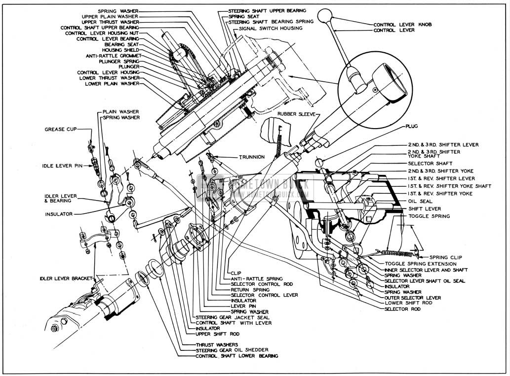
1950 Buick Synchromesh Transmission Shift Mechanism-Series 40-50
The gear shift control lever pivots on a ball joint formed in outer end of the control lever housing. A spherical shoulder on the lever seats in a similarly shaped fabricated rubber bearing which is supported between the housing nut and a stamped steel bearing seat. The ball shaped inner end of control lever seats in a socket formed in the upper end of the selector control rod, which is located inside the steering gear column jacket. The end of control lever is firmly held in the rod socket by a spring loaded plunger. See figure 4-18.
The upper end of selector control rod is supported in a bearing machined in the control lever housing. The lower end of control rod is connected by a pin to the selector control which is supported on a bracket welded to lower end of the column jacket. The selector control lever is connected to the outer selector lever on transmission by the lower selector rod, which has a trunnion at the forward end for adjustment. The trunnion pin seats in a rubber insulator in the selector control lever to prevent noise at this connection. See figure 4-18.
A return spring connected between the column jacket and upper end of selector control lever operates to pull the gear shift control lever downward. An anti-rattle spring connected between the dash and a clip on lower selector rod also assists in pulling the control lever downward. In the neutral position, therefore, the control is always in position for a shift into second or third speed and must be raised for a shift into first or reverse.
Gear Shift Control Mechanism
Shifting into gear after selection has taken place, or shifting out of gear is controlled by the shift control lever on steering gear column, the control shaft inside the column, and the linkage which connects the control shaft to the shaft lever on selector shaft in transmission. Forward movement of control lever causes rotation of the selector shaft to produce a shift into reverse or second speed, depending on the selection. Rearward movement of control lever similarly produces a shift into first or third speed. See figure 4-18.
The housing in which the shift control lever is mounted is a slip fit over the upper end of the tubular control shaft, which encircles the steering shaft. The control shaft is slotted in two places to key to the lever housing, which is held tight on shaft by a clamp screw. The upper end of housing and shaft assembly is supported in a metal and fabric bearing seated in the signal switch housing. Upward thrust of the assembly is taken by a fabric thrust washer, plain washer, and spring washer placed between the lever housing and switch housing. Downward thrust is taken by a fabric thrust washer and a plain washer placed between lever housing and a plate welded into the column jacket. See figure 4-18.
The lower end of control shaft is reduced in diameter and is supported by a metal and fabric bearing seated in the steering gear housing. An oil shedder is pressed into steering gear housing over the bearing and the shedder is covered by a cup welded to the control shaft, to form a s al against entrance of dirt and water.
A lever welded to control shaft is connected by a short upper shift rod to the idler lever mounted on a bracket attached to steering gear housing. The idler lever is bushed and carried on a shouldered pin attached to bracket by a nut and washer. The pin is drilled and ‘fitted with a grease fitting for lubrication. A long lower shift rod, provided with an adjustable clevis, connects the idler lever to the shift lever on selector shaft in transmission. Rubber insulators seated in the levers prevent noise at the connection with both ends of both shift rods. See figure 4-18.
4-10 1950 BUICK SYNCHROMESH TRANSMISSION TROUBLE DIAGNOSIS
Hard Shifting and Block-out
Hard shifting may be caused either by conditions in shift control mechanism in-steering column or by conditions in transmission assembly. Disconnect lower shift rod at idler lever to determine which unit is at fault.
Conditions in shift control mechanism which may cause hard shifting are: (1) Control shaft upper or lower bearing scored or distorted. (2) Control lever housing upper thrust washer broken or improperly installed in signal switch housing. (3) Selector control rod bent or rubber sleeves binding against jacket.
Conditions in transmission assembly which may cause hard shifting are. (1) If there is excessive resistance at start of shift, shifter yoke shaft poppet spring probably too stiff. (2) Shifter yoke shaft may be bent. (3) Selector shaft bent, or binding in oil seal may cause hard shifting or hard selection.
Block-out of second or third gear may be caused by scored synchronizing drums or the cones on gears. Rough cam surfaces on ends of sliding sleeve or on synchronizing drum will also cause block-out.
Low and Reverse Gear Clash
Transmission gears can be made to clash by shifting into low or reverse gear too quickly after clutch pedal is depressed, even though clutch is in perfect working order. This is because inertia of clutch driven plate causes the plate to spin until it is stopped by friction of transmission and transmission lubricant. With warm transmission lubricant and low friction transmission bearings, a reasonable amount of spin is to be expected. The spin does not occur when shifting quickly into second or high gear because the synchronizing unit stops the driven plate.
To eliminate gear clash, sufficient time MUST be allowed before shifting into low after pedal is depressed or else starts must be made in second gear. There is no objection to making starts in second gear on level ground since the clutch slippage under ordinary driving conditions is not sufficient to produce enough heat to damage driven plate facings.
If gear clash continues after allowing proper time for clutch driven plate to stop, check clutch pedal lash and adjust to specified limits. See paragraph 4-4. In exceptional cases of driven plate spinning, clutch pedal lash should be maintained at 1/2″. Make sure that idle speed of engine when hot is 450 RPM. A faster idle aggravates driven plate spinning.
Conditions within the transmission which may cause gear clash are: ( 1) Faulty synchronizing drums or cone surfaces; (2) Excessive main shaft end play. Gear clash also may be caused by a dragging clutch plate. See paragraph 4-3 (d).
Noise in Neutral
With car standing, engine running, and transmission in neutral, the transmission parts in operation are: main drive gear and bearing, counter gear and bearings, reverse idler gear, second speed gear, main shaft pilot bearing. Disengaging clutch will stop movement of all these parts. By disengaging and engaging clutch it can be determined whether noise originates in these transmission parts and whether the noise is normal. Noise in neutral in the form of a constant regular click is usually caused by a nicked gear or bearing.
Gear Noise
Some gear noise is to be expected in all except third speed. Comparison with another car is the only means of determining whether or not gear noise is excessive. Before removing transmission for correction of gear noise determine by test which gears are noisy under load, so that these can be thoroughly inspected when removed.
Gear Rattle During Acceleration
Improperly calibrated clutch driven plate, faulty crankshaft balancer, or scored rear axle gears may cause rattle in transmission in third speed, on acceleration. Rattles occuring on wide open throttle between 40 and 60 MPH are usually caused by improper clutch driven plate dampening; a new driven plate should be installed if rattles are objectionable.
Noise When Shifting out of First or Reverse
Shifting out of first or reverse very slowly will usually result in some noise just as the gears disengage. This is normal because of the gear pointing necessary for easy engagement.
Abnormal noise during normally fast shift may be caused by improper clutch release. Check clutch pedal lash and adjust. See paragraph 4-4.
Abnormal noise during normally fast shift, when clutch release is satisfactory, may be caused by damage to pointing on engaging side of teeth on counter gear, reverse idler gear or first and reverse sliding gear. Noise when disengaging both first and reverse, indicates that fault is with sliding gear only. Noise when disengaging reverse only indicates reverse idler gear at fault. Noise when disengaging first speed only indicates counter gear at fault. Tests must be made by disengaging gears while car is still in motion.
Gear Jump-out
In any case of gear jump-out, first check the adjustment of gear shift control mechanism as described in paragraph 4-11. Make certain that poppet balls have full engagement in notches in shifter yoke shaft in all speed positions and neutral. Also make certain that toggle spring extension is not distorted so that it contacts the selector shaft. If these items do not correct gear jump-out, remove transmission for examination of parts.
Gear jumping out of third speed may be caused by misalignment between the flywheel housing and crankshaft. See paragraph 2-33 for alignment correction procedure.
Gear jumping out of third speed also may be caused by excessive run-out of front face of transmission case. See paragraph 4-14 (subpar. b) for checking procedure.
Gear jump-out in any transmission speed position may be caused by loose fit of bearings or bushings involved, weak poppet springs, loose fit of sliding sleeve on main shaft, loose fit of sliding gear on sliding sleeve, worn teeth on mating gears. All items should be carefully inspected.
1950 Buick Synchromesh Transmission Lubricant Passing to Rear Axle
1950 Buick Synchromesh transmission lubricant may pass into rear axle assembly as a result of:
- Scored universal joint or bushing.
- Clearance of more than .006″ between universal joint and bushing in torque ball.
- Worn oil seal in torque ball.
- Loose torque ball adjustment.
- Excessive run-out of front end of propeller shaft.
Scored or Broken Gear Teeth
Gear teeth will be seriously damaged and possibly broken, by failure of car operator to fully engage gears on every shift before engaging clutch and applying engine power.
The type of damage resulting from failure to obtain full engagement is shown in figure 4-19. The conditions illustrated were produced on new gears intentionally shifted improperly a few times to determine what damage would result.
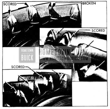
1950 Buick Gear Teeth Damaged by Improper Gear Shifting
Considerable damage to gears and bearings will result from running at abnormal speeds in reverse, first, and second speed gears. This practice is also detrimental to the engine.
4-11 ADJUSTMENT OF SHIFT CONTROLS-REPLACEMENT OF PARTS
Selector Control Adjustment
The following steps are required to insure that the shifter levers in transmission make full engagement with the shifter yoke shafts as selected. See figure 4-18.
- Shift transmission to neutral and disconnect selector rod from selector control lever.
- Inspect rubber insulator in selector control lever and replace insulator if worn. Make sure that lever return spring is strong enough to pull selector control lever up so that the gear shift control lever is held all the way down.
- Move selector rod back and forth to make sure that selector shaft in transmission moves freely. A bind at this point will prevent return spring from automatically dropping shift control lever to second speed side on shift from first to second speed.
- Hold selector rod to the rear as far as possible and adjust trunnion until trunnion pin is centered in hole in selector control lever insulator.
- Connect trunnion to selector control lever with a fiber washer on each side of insulator and lock with cotter pin.
Gear Shift Control Adjustment
The following steps are required to insure that gears are fully engaged on all shifts. See figure 4-18.
- Shift transmission into second speed and disconnect lower shift rod from the shift idler lever.
- Inspect for wear and lost motion in rubber insulators located in control shaft lever, idler lever, and shift lever on selector shaft; replace any worn insulators. If idler lever has excessive play on idler lever pin, replace worn parts.
- While pulling forward on lower shift rod to insure full engagement in second speed, adjust clevis on shift rod so that when clevis is connected to idler lever a clearance of 1/8″ exists between the shift control lever housing and the edge of opening in steering gear column jacket.
- With lower shift rod connected to idler lever and lock nut tightened against clevis, shift into third speed. A clearance of approximately 1/8″ should exist between control lever housing and column jacket. Make certain that specified clearance exists between control lever housing and column jacket in all speed positions.
Replacement of Shift Control Parts
The gear shift control lever, bearing, and bearing seat may be removed by unscrewing the control lever housing nut. Unscrew knob from lever to remove housing nut. A rubber anti-rattle grommet fits into a groove in the inner end of control lever. When installing a new bearing on control lever, the large diameter of bearing must be toward the lever knob. Before installing control lever, coat inner end and socket in selector red with Lubriplate. During installation of lever be careful to draw housing nut tight so that shoulder in nut will seat against flange of bearing seat and lock the seat in place.
The control shaft upper bearing and control lever housing upper thrust washer may be replaced by removing the signal switch housing. The procedure for replacement of these parts is given in paragraph 7-7.
Replacement of selector rod, control shaft, and lower bearing requires removal of steering column jacket. The steering gear should be removed, or at least moved down from instrument panel to provide proper working space and avoid damaging interior of body. Replacement of these parts is covered in paragraph 7-9 covering disassembly and assembly of steering gear.
4-12 ADJUSTMENT OF TORQUE BALL
Correct adjustment of the torque ball is very important. If torque ball is loose and has end play it will be noisy and will act as a pump to cause leakage of transmission lubricant. If torque ball is too tight, it will cause transmission misalignment, scoring of ball and retainers, and may cause breakage of bolts which attached torque ball to torque tube.
- Disconnect rear axle assembly and move it back out of the way (par. 5-7).
- Disconnect thrust plate from the rubber thrust pad on transmission support, then remove torque ball boot, thrust plate, gasket, torque ball retainers, and shims from rear bearing retainer. NOTE: Mark top edge of outer retainer before removal so that retainer can be reinstalled in original position.
- Clean and inspect spherical surfaces of torque ball and both retainers. Inspect bushing and universal joint oil seal in torque ball. Inspect torque ball boot. Replace parts which are excessively worn, damaged or scored.
- When installing a new universal joint oil seal in torque ball, place seal in position with the feather edge pointing into torque ball, then press seal squarely into place, using a flat piece of metal to avoid distorting seal. Press new seal flush with boss on flange of torque ball. NOTE: Oil seal should be stored in neatsfoot oil to keep leather soft and pliable. Do not use seal having a, hard, dry leather.
- Prepare two 3/8″ headless guide pins 1 3/8″ long, having 3/8″-16 threads 1/2″ long and screwdriver slots cut in opposite end. Install guide pins in upper bolt holes in rear bearing retainer . flange. See figure 4-22.
- Place one gasket or shim (having 3 notches in outer edge) and the inner retainer on guide pins, with oil drain hole and notch in edge of retainer straight down.
- Lubricate leather oil seal and bearing surfaces of torque ball and retainers with transmission lubricant. Place torque ball in outer retainer so that “TOP” mark on ball and the marked edge of retainer are together.
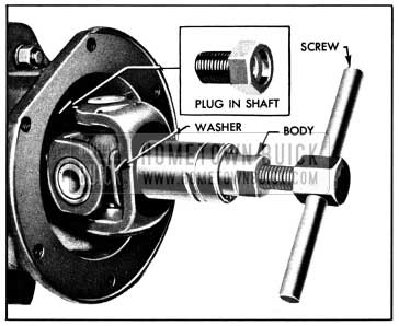
- Assemble sleeve and plug of Installing Tool J 2597 together (fig. 4-20), then push tool through rear side of oil seal until the leather edge is on the plug, at which time the sleeve will drop off the plug. See figure 4-21.
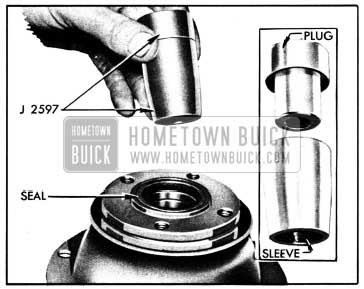
1950 Buick Torque Ball Installing Tool J 2597
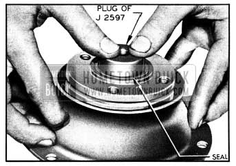
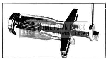
1950 Buick Pushing Installing Tool into Universal Joint Oil Seal
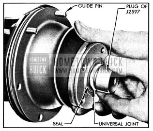
1950 Buick Installing Torque Ball and Retainer
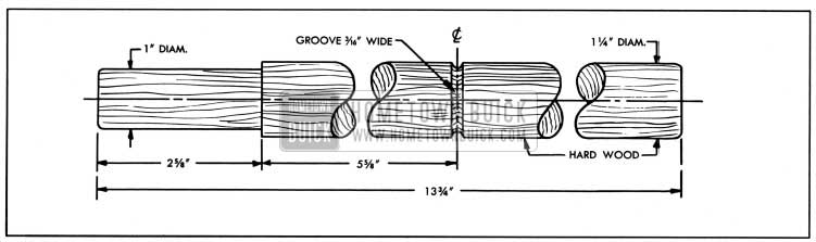
1950 Buick Club for Adjusting Torque Ball
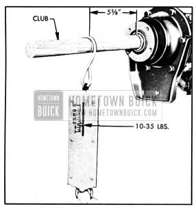
1950 Buick Checking Torque Ball Drag
A drag of 10 to 35 pounds should be obtained. If torque ball is too tight or too loose, loosen bolts and repeat the centering and tightening operation, then recheck drag with club and spring scale.
After changing shims always install ball and retainer with top sides up and use the centering, tightening, and checking procedures specified in steps 12 and 13 above.
Final adjustment must provide a drag of 10 to 35 pounds on club with a 5 5/8″ leverage. See figure 4-24.
- Install torque ball boot. Turn the large end back over small end, engage rib in small end in groove on flange of torque ball, then turn large end forward to engage rear end of outer retainer.
- Install shims between thrust plate and thrust pad (fig. 4-28) and tighten thrust pad stud nuts. Connect rear axle assembly (par. 5-7).
4-13 REMOVAL AND INSTALLATION OF 1950 BUICK SYNCHROMESH TRANSMISSION
CAUTION: The rear end of engine must be firmly supported during removal and installation of the transmission. The use of a jack or blocks is dangerous because of the possibility of slipping and letting the engine fall.
A safe and convenient engine support bar with two hooks can be made locally from the details given in figure 4-25.
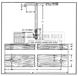
1950 Buick Engine Support Bar and Hooks
Removal of 1950 Buick Synchromesh Transmission
- Disconnect rear axle assembly and move it back out of the way (par. 5-7).
- Drain transmission lubricant. Fill with clean gasoline or kerosene and run transmission in neutral for about 15 seconds. Drain cleaner.
- Disconnect speedometer cable, lower shift rod, and lower selector rod. Remove toggle spring and extension, remove shift lever and lock washer from selector shaft and remove outer selector lever, to provide clearance for removing. transmission to flywheel housing bolts. Hold shift lever in neutral while removing attaching bolt, to avoid damaging shifter lever on shaft inside transmission.
- Support rear end of engine by installing support bar (fig. 4-25) under rear end of lower crankcase. Place left side hook over frame between brake master cylinder and clutch release equalizer. Tighten nuts on both hooks evenly. See figure 4-26.
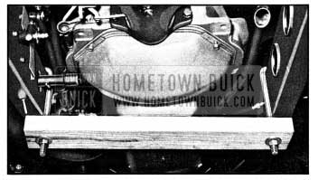
1950 Buick Support Bar under Rear End of Engine
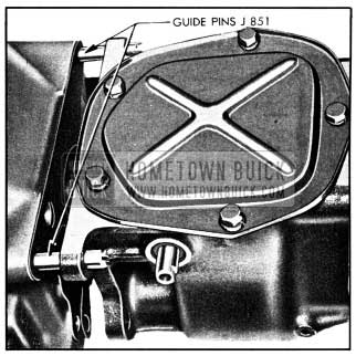
1950 Buick Transmission Guide Pins J 851
Installation of 1950 Buick Synchromesh Transmission
- Lightly coat the splines on end of main drive gear with Lubriplate for a distance of not more than 1″. Do not apply an excess that will push off at driven plate hub and get on driven plate facings.
- Make certain that front face of transmission case and face of flywheel housing are absolutely clean. Install Guide Pins J 851 in upper bolt holes in housing (fig. 4-27) and install a new transmission gasket. Make certain that spring washer is in place behind clutch release bearing support in housing.
- Lift transmission into place and fully support it until the main drive gear bearing enters flywheel housing. Clutch driven plate will be damaged if guide pins are not used and weight of transmission is allowed to rest on main drive gear in driven plate hub.
- Install lower transmission attaching bolts, then the upper bolts, and tighten all bolts evenly and securely. CAUTION: If a gap exists between transmission case and flywheel housing do not tighten bolts as case may be broken. Remove transmission and check position of main drive gear bearing snap ring, which may have slipped out of place during installation.
- Install rubber thrust pad on thrust plate attached to torque ball. Install transmission support and attach transmission mounting pad to the support with bolt plate and self-locking nuts. Remove support bar from under the engine so that full weight rests on transmission mounting pad.
- With engine and transmission resting freely and normally on mountings, install sufficient shims between the thrust pad and transmission support to fill the existing space. Insert shims from above with tabs on right side, then install the bolt plate and three nuts which attach thrust pad to support. See figure 4-28.
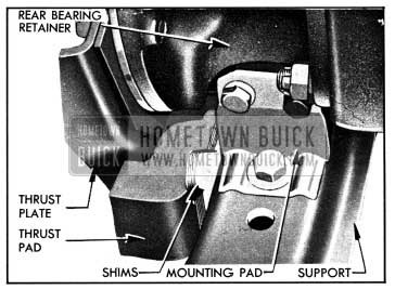
1950 Buick Transmission Mounting Pad, Thrust Pad and Shims
- Correct synchronization when shifting into second and third speed.
- First and second speed slip-out, on drive and coast.
- Gear, bearing, or shifter yoke noises in all speeds and neutral.
- Rattles in shaft control mechanism.
4-14 DISASSEMBLY, INSPECTION AND ASSEMBLY OF 1950 BUICK SYNCHROMESH TRANSMISSION
Some form of fixture for securely holding the transmission during disassembly and assembly is essential. The transmission stand shown in figure 4-29 may be made locally from details given in BPS 2.222, or figure 4-36 in the 1948-49 Buick Shop Manual.
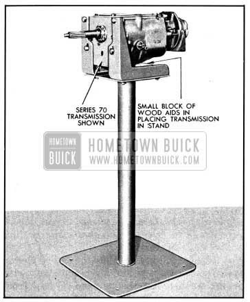
1950 Buick Transmission Supported in Stand
If a stand is not desired, the upper section may be mounted on a work bench. Do not clamp the transmission case in a vise.
Disassembly of 1950 Buick Synchromesh Transmission
- Thoroughly clean all dirt from exterior of transmission to avoid getting dirt into bearings when transmission is opened. Remove transmission cover and gasket.
- Lock transmission in third speed to prevent sliding sleeve and sliding gear from dropping, then remove transmission rear bearing retainer, universal joint, torque ball, and main shaft as an assembly.
- Remove the four set screws from shifter levers and shifter yokes, using Remover J 2895. See figure 4-30.
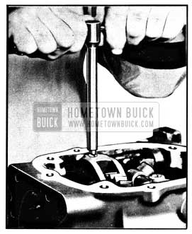
1950 Buick Removing Set Screw with Remover J 2895
1950 Buick Disassembly of Main Drive Gear
1950 Buick Removing Universal Joint with Puller J 682-A
1950 Buick Removing Worm Gear with Puller J 1134-H
Cleaning and Inspection of 1950 Buick Synchromesh Transmission Parts
Clean and inspect all ball and roller bearings as described under Bearing Service (par. 1-11 and 1-12). Thoroughly clean all other parts except rubber mountings in CLEAN solvent and wipe dry with CLEAN cloths. Inspect parts as follows:
- Gears and Shafts. Carefully inspect teeth and other ground surfaces of all gears for wear, scoring, pitting, chips, nicks, and burrs. Do not confuse manufacturing cutter marks with scores or pits. Conical surfaces of gears where contacted by synchronizing drums must be smooth and free of burrs. Slight scores or burrs may be honed off with a fine stone, however, if any gear is chipped or excessively worn it should be replaced.
Inspect all shafts for wear roughness on bearing surfaces. Check fit of gears on shafts upon which they are mounted. The sliding sleeve must slide freely on splined section of main shaft, but without appreciable backlash. - Synchronizing Drums. The cam surfaces of synchronizing drums must be smooth. The conical surfaces of synchronizing drums must be free of burrs or scores, and oil grooves must be clean. Never polish this surface or change the angle.
- Selector Shaft, Shifter Yokes and Shafts, Toggle Spring Extension. Check selector shaft and shifter yoke shafts on a flat surface to see whether they are bent. A bent shaft will cause hard shifting, and should be replaced. If a shifter yoke is bent or has rough contact surfaces it will cause hard shifting and noise, therefore, it should be replaced. Replace poppet springs if distorted or of doubtful strength.
Check toggle spring extension to make sure it is not distorted. An improperly shaped extension will bear against the selector shaft and actually tend to pull transmission out of second speed. Figure 4-34 shows the correct shape for extension. A bent extension should be reshaped to dimension shown, or replaced.
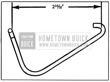
1950 Buick Toggle Spring Extension
The front yoke must be a tight fit, rotatively, on main shaft to prevent “snap” when alternating car movement between forward and reverse. The rear yoke of universal joint and bushing in torque ball must be free of scores and not worn excessively; clearance between these parts should be .004″ to .006″.
If the transmission had been jumping out of third speed, the alignment of flywheel housing with engine crankshaft should be checked as described in paragraph 2-33 and front face of transmission case should be checked for runout using Checking Fixture J 2240, which may be borrowed from a Buick Zone Office or may be made locally from dimensions given in BPS 2.200, figure 7.
- Install the adapter and mandrel in case, then mount dial indicator on mandrel so that indicator stem bears against front face of transmission case 3″ from center of mandrel. See figure 4-35.
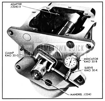
1950 Buick Checking Run-out of Transmission Case
- Rotate mandrel while pressing it against case and note dial indicator reading. Total indicator reading should not exceed .003″. If runout exceeds .003″, replace transmission case with one that checks within the allowable limit on run-out.
Assembly of 1950 Buick Synchromesh Transmission
Assemble the transmission by reversing the sequence of steps given for disassembly. In addition, observe the following instructions that apply to assembly.
- Condition of Parts. Make certain that all parts are absolutely clean and that gears and synchronizing drums are free of nicks or burrs. Use all new gaskets and oil seals or packings to insure against leakage of lubricants. Use all new snap rings, and retainers of snap ring type.
Snap rings are frequently distorted during removal and are difficult to true up satisfactorily for further service.
- Observe instructions given under Bearing Service (1-9) on proper installation of ball bearings. Coat bearings with clean transmission lubricant at time of installation, to insure initial lubrication.
- Universal Joint. Use Replacer J 865 to install universal joint on main shaft. See figure 4-36.
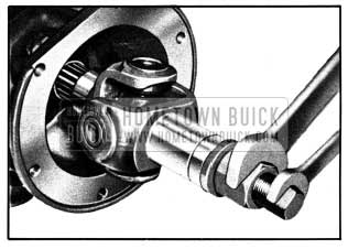
1950 Buick Installing Universal Joint with Replacer J 865
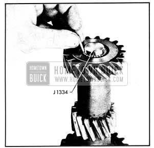
1950 Buick Installing Counter Gear Bearings with Loader J 1334
Pack bearing rollers in white vaseline to hold them in place and make certain that all rollers are installed (25 in each bearing). Leave loader in gear until it is pushed out by the counter gear shaft during installation.
Install locking ball in counter gear shaft then install shaft through rear end of case, driving rear end of shaft slightly below face of case so that rear bearing retainer may be tightened against its gasket.
- Main Shaft Snap Ring. Use Snap Ring Replacer J 1267 to install the snap ring and avoid distorting ring. See figure 4-38.
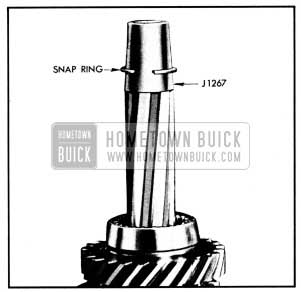
1950 Buick Snap Ring Replacer J 1267
Leave A Comment
You must be logged in to post a comment.