SECTION 8-C 1950 BUICK BRAKE SERVICE AND ADJUSTMENT PROCEDURES
8-8 FILLING 1950 BUICK BRAKE MASTER CYLINDER
The fluid level must be maintained at 1/2″ to 1″ below top of master cylinder filler opening at all times. Low fluid level in master cylinder reservoir may permit air to be pumped into the brake pipes and wheel cylinders, necessitating bleeding of the hydraulic system.
Before removing filler cap nut to check fluid level or add fluid, thoroughly clean the cap and surrounding area of cylinder to avoid getting dirt into reservoir. It is recommended that Master Cylinder Filler J 713 and Adapter J 713-2 (fig. 8-5) or a pressure tank be used when filling master cylinder reservoir, to avoid entrance of dirt into the reservoir or the fluid container.
Use only G. M. or Delco Super No.11 hydraulic Brake Fluid. This is an all-weather fluid which will operate satisfactorily in all temperatures and will mix properly when new fluid is added to fluid in the hydraulic system. Do not use reclaimed fluid.
Do not use shock absorber fluid or any other fluid which contains mineral oil. Do not use a container which has been used for mineral oil. Even a trace of mineral oil will cause swelling and distortion of rubber parts in the hydraulic brake system.
8-9 BLEEDING 1950 BUICK BRAKE HYDRAULIC SYSTEM
A bleeding operation is necessary to remove air whenever it is introduced into the hydraulic brake system. Since air is compressible and hydraulic fluid is not, the pressure of air in the system is indicated by a springy, spongy feeling on the brake pedal accompanied by poor braking action.
Air will be introduced into the hydraulic system if the brake pedal is operated when the fluid is too low in master cylinder reservoir. Air will also enter the system whenever any part of hydraulic system is disconnected.
It will be necessary to bleed the hydraulic system at all four wheel cylinders if air has been introduced through low fluid level or by disconnecting brake pipe at master cylinder. If brake pipe is disconnected at any wheel cylinder, then that wheel cylinder only need be bled. If pipes are disconnected at any fitting located between master cylinder and wheel cylinders, then all wheel cylinders served by the disconnected pipe must be bled. See figure 8-2.
Sequence for Bleeding Wheel Cylinders
It is advisable to bleed one wheel cylinder at a time to avoid getting fluid level in reservoir dangerously low. The correct sequence of bleeding is left front, right front, left rear, right rear. This sequence expels air from the lines and wheel cylinders nearest to the master cylinder first, and eliminates the possibility that air in a line close to the master cylinder may enter a line farther away after it has been bled.
CAUTION: Do not perform bleeding operation while any brake drum is removed.
Bleeding Wheel Cylinder with Master Cylinder Filler J 713
- Thoroughly clean master cylinder filler cap nut and surrounding area, then remove cap nut.
- Fill Master Cylinder Filler J 713 with specified brake fluid (par. 8-8) and use Adapter J 713-2 to support the filler in place on master cylinder. See figure 8-5.
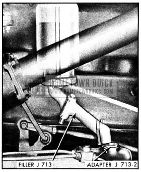
1950 Buick Master Cylinder Filler and Adapter
Leave Filler J 713 in place during all bleeding operations as it automatically maintains the proper level in reservoir as fluid is pumped out of master cylinder.
- Remove screw and attach Brake Bleeder Tube J 628-A to wheel cylinder bleeder valve. Place lower end of bleeder tube in a clean glass jar. Unscrew bleeder valve 3,4. of a turn, using Bleeder Wrench J 627. See figure 8-6.
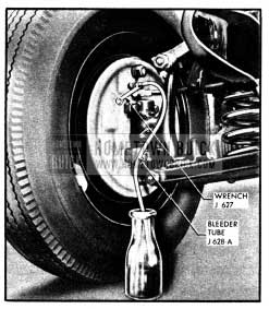
1950 Buick Bleeding Wheel Cylinder
- Depress brake pedal a full stroke, then allow pedal to return slowly to released position. Allowing pedal to return quickly may draw air into system. Continue operating pedal in this manner until fluid flows from bleeder tube into glass jar in a solid stream that is free of air bubbles, then close the bleeder valve securely.
Remove bleeder tube and install screw in valve.- After bleeding each wheel cylinder check filler jar to make sure it contains enough fluid for the next bleeding operation. Approximately one-half pint of fluid is required to bleed each wheel cylinder. Allowing reservoir to be emptied will cause air to be drawn into hydraulic system.
- When bleeding operation is completed at all wheel cylinders where needed, make sure that fluid level is 1/2″to 1″ below top of master cylinder filler opening then install filler cap nut and gasket.
- Discard the brake fluid deposited in glass jar during bleeding operation. It is poor economy to attempt to clean fluid that has once been used.
- Test brakes (par. 8-5).
Bleeding Wheel Cylinder with Pressure Tank
IMPORTANT: When using a pressure tank, air bubbles may form in the tank and enter the brake hydraulic system. To avoid this observe the following points when handling a pressure tank: (1) Do not shake or agitate the pressure tank after air pressure has been added or is being added. (2) Allow pressure tank to stand in one position as much as possible, and bring air hose over to tank when adding head of air. (3) Make certain the valves on the pressure tank lines are not defective allowing air to be sucked in when fluid passes through the lines. (4) Pressure tank should be kept at least 1f3 full of fluid to avoid air bubbles forming. (5) If pressure tank is full of air bubbles, release air pressure and those bubbles will increase in size and be forced to top of fluid, and escape.
- Thoroughly clean master cylinder filler cap nut and surrounding area, then remove cap nut.
- Make sure that pressure tank is at least 1/3 full of specified brake fluid (par. 8-8), that hose and master cylinder reservoir are filled with fluid, then attach hose to master cylinder filler opening.
- Remove screw and attach Brake Bleeder Tube J-628-A to wheel cylinder bleeder valve.
Place lower end of bleeder tube in a clean glass jar. Unscrew bleeder valve 3/4 of a turn, using Bleeder Wrench J 627. See figure 8-6.
- Open pressure tank hose valve to apply fluid to master cylinder under pressure that does not exceed 35 pounds. Too much pressure may blow out the expansion plug in master cylinder. It is not necessary to pump the brake pedal when using pressure tank.
- When fluid flows from bleeder tube into glass jar in a solid stream that is free of air bubbles, that particular cylinder and line are bled; tighten bleeder valve securely, remove bleeder tube and install screw in bleeder valve.
- When bleeding operation is completed at all wheel cylinders where needed, make sure that fluid level is 1/2″ to 1″ below top of master cylinder filler opening then install filler cap nut and gasket.
- Test brakes (par. 8-5).
8-10 FLUSHING 1950 BUICK BRAKE HYDRAULIC SYSTEM
It is recommended that the entire hydraulic system be thoroughly flushed and cleaned every 15,000 miles, or whenever new parts are installed in the hydraulic system, or new shoes or linings are installed. Flushing is also recommended if there is any doubt as to the grade of fluid in the system or if fluid has been used which contains the slightest trace of mineral oil.
M. Declene Flushing Fluid, Group 4.683, is recommended as the most satisfactory flushing and cleaning fluid. It is red in color to distinguish it from brake fluid and thereby indicate when it is coming through the hydraulic system clear of dirt and old fluid. If Declene is not available, specified brake fluid (par. 8-8) or a good grade of alcohol may be used for flushing. Gasoline, kerosene, or any other fluid containing even a trace of mineral oil must not be used as such fluids will cause serious damage to rubber parts.
Flushing is performed at each wheel cylinder in turn, and in the same manner as the bleeding operation (par. 8-9) except that bleeder valve is opened 1 1/2 turns and the cleaning fluid is forced through the pipes and wheel cylinder until it emerges clear in color. Approximately one quart of cleaning fluid is required to flush the hydraulic system thoroughly.
When flushing is completed at all wheel cylinders, substitute specified brake fluid at master cylinder and repeat the operation at each wheel cylinder in turn until clear brake fluid emerges in a solid stream free of air bubbles. Make sure that all cleaning fluid is forced out of hydraulic system by the fresh brake fluid as neither Declene nor alcohol is a satisfactory brake fluid. Also, make certain that master cylinder reservoir is filled to proper level when job is completed.
8-11 1950 BUICK BRAKE PEDAL ADJUSTMENT
The brake pedal adjustment is provided to insure full pedal stroke and proper clearance at toeboard in the released position. When brake pedal is in released position, the push rod stop (K) must bear against the stop plate (L) in master cylinder. See figure 8-4.
- Before attempting to adjust brake pedal, be certain that pedal returns to stop freely, is not binding on pedal shaft or in floor mat, and that pedal return spring has not lost its tension.
- Depress pedal slightly and then return it against the stop, which will be indicated by a metallic click. At this point, the clearance between brake pedal and toeboard should be 1″. See figure 8-7.
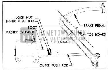
1950 Buick Brake Pedal Clearance Adjustment
- If clearance is not correct, loosen the locknut and turn master cylinder inner push rod with pliers until correct clearance is obtained. Hold push rod while tightening lock nut.
On Dynaflow Drive cars only, if correct adjustment of pedal cannot be obtained at push rod, or difficulty is experienced with dragging brakes, check the position of the pedal and the master cylinder operating lever on the pedal shaft. The pedal, lever, and both ends of shaft have marks which must be aligned so that pedal and lever will be in proper relation to each other. See figure 8-8. If either part is improperly installed on the shaft, remove it and reinstall so that assembly marks are aligned. Each part is keyed to the shaft by serrations and held by a clamp bolt.
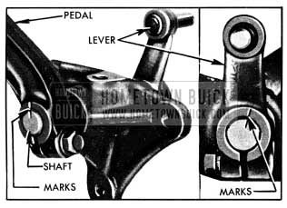
1950 Buick Marks for Installation of Brake Pedal and Lever on Shaft
8-12 MINOR 1950 BUICK BRAKE ADJUSTMENT
The minor brake adjustment is intended for use where braking action is equal and generally satisfactory except that brake pedal goes too close to toeboard due to wear of brake linings. If braking action is unequal or otherwise unsatisfactory, the major brake adjustment should be used (par. 8-15).
Do not adjust when brakes are warm. Brake drums should be approximately room temperature.
- Jack up all four wheels in a safe manner.
- Check fluid level in master cylinder reservoir and add fluid if necessary (par. 8-8).
- Check brake pedal for free action, proper return to stop, and proper clearance at toeboard (par. 8-11).
- Check all anchor pin nuts with 16″ Wrench J 854 to make certain nuts are tight. See figure 8-9.
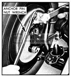
1950 Buick Using Anchor Pin Nut Wrench J 854
If an anchor pin nut is found loose, reset anchor pin to centralize brake shoes as instructed in paragraph 8-15, step 17.
- Fully release parking brake lever. Back off cable adjusting nut at brake cable sheave while holding rod on end of cable to prevent it from twisting. Pull on both ends of rear brake cable a number of times to make sure that cables operate rear brake shoes freely and do not bind in conduits. Check for free movement of cable in brake cable sheave and check brake cable spring for tension. If cable action is not free, the cable and sheave should be lubricated (par. 8-14). Replace a weak or broken cable spring.
- Remove adjusting hole covers from brake backing plates. Using Shoe Adjuster J 1603-A to turn brake adjusting screw, expand brake shoes at each wheel until the wheel can just be turned by hand. Moving outer end of tool upward toward center of wheel expands the shoes. See figure 8-10. The drag should be equal at all wheels.
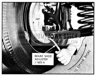
1950 Buick Expanding Brake Shoes with Tool J 1603-A
- While holding brake lever cable to prevent twisting, tighten cable adjusting nut at cable sheave until rear brake cable is taut.
- Back off adjusting screw at each wheel 15 notches. If shoes drag on drums, back off adjusting screw one or two additional notches. Install adjusting hole covers in all brake backing plates.
- Remove jacks and road test car for service and parking brake performance (par. 8-5 and 8-6).
8-13 1950 BUICK PARKING BRAKE ADJUSTMENT
Adjustment of the parking brake is included in the minor brake adjustment described in paragraph 8-12. It is advisable to use the complete minor brake adjustment if the position of brake pedal, when applied, indicates that some brake lining wear has taken place since brakes were last adjusted. In this case, adjustment of parking brakes only will result in the front brake shoes having more clearance than the rear shoes.
If brake linings have not worn appreciably, it is permissible to adjust parking brakes separately to take up slack in brake cables. Jack up rear wheels only and adjust parking brakes by performing steps 5 through 8 of minor brake adjustment (par. 8-12). Do not attempt to adjust parking brakes by simply tightening adjusting nut at brake cable sheave as this practice may result in taking up necessary clearance of brake shoes and cause them to drag.
8-14 LUBRICATION OF 1950 BUICK PARKING BRAKE CABLES
Lubrication of parking cables is not included in Lubricare Instructions (par. 1-1) since these cables are usually lubricated during a major brake adjustment. Vehicles habitually operated under conditions where mud and water are frequently encountered may require more frequent lubrication to insure free action and avoid excessive wear of cables.
- Disconnect brake lever cable at cable sheave (equalizer). See figure 8-2.
- Disconnect rear brake cable conduits from rear brake backing plates and from clips on strut rods.
- Slide each conduit away from backing plate and coat the cable sparingly with Bendix or Delco Brake Lubricant, or Lubriplate. Also lubricate cable where it passes through the sheave and make sure cable slides freely in sheave.
- Slide conduit to within 2″ of normal position, then clean surplus lubricant from cable at backing plate to avoid forcing it into brake assembly where it will get on brake linings.
- Connect conduits to clips on strut rods and to backing plates.
- Although the brake lever cable rarely needs lubrication it may be lubricated at this time by disconnecting cable at brake lever and removing exposed portion from grommets under torque tube. Heavily coat exposed section under torque tube with graphite lubricant, then pull cable out of conduit at upper end. This will cause lower section of cable to deposit lubricant in rear end of conduit. Coat upper end of cable with graphite lubricant, then pull upper end of cable back into conduit and connect to brake lever.
- Connect brake lever cable at cable sheave and adjust parking brakes (par. 8-13).
8-15 MAJOR 1950 BUICK BRAKE ADJUSTMENT
The major brake adjustment is intended for use when braking action is unequal, severe, or otherwise unsatisfactory, or when the car has been driven sufficient mileage to warrant a thorough inspection and cleaning of the brake assemblies and drums.
Throughout the adjustment procedure additional operations are specified where inspection indicates their need. Each additional operation is identified by an asterisk (*) preceding the reference to paragraph number covering the operation. The major brake adjustment combined with required additional operations constitute a general overhaul of the entire brake mechanism.
- Jack up car in a safe manner and remove all wheels.
- Check fluid level in master cylinder reservoir and add fluid if necessary (par. 8-8).
- Check brake pedal for free action, proper return to stop, and proper clearance at toeboard (par. 8-11).
- Pump brake pedal a number of times with quick release. If pedal develops a very solid feel and reduced travel, and brakes drag heavily when drums are turned, it indicates that the compensating port in master cylinder is blocked by a distorted piston primary cup. If brake pedal goes slowly down when steady pressure is applied, and no leaks are found in inspection described later, it indicates a distorted primary cup or scored master cylinder barrel. Either condition required overhaul of master cylinder (*par. 8-19).
- Inspect all brake pipe and hose connections for evidence of fluid leakage. See figure 8-2. Tighten any leaking connection, apply heavy pressure to brake pedal to build pressure in hydraulic system, and recheck connections.
- Remove rear brake drums, and front hub and drum assemblies. NOTE : Since stops are located on brake backing plates to prevent pistons from leaving wheel cylinders, it is not necessary to install wheel cylinder clamps when drums are removed; however, brake pedal must not be operated while drums are removed.
- Clean all dirt out of brake drums, using care to avoid getting dirt into front wheel bearings. Inspect drums and replace or recondition if required (*par. 8-17).
- Inspect front wheel bearings and oil seal packings. Replace faulty bearings or packings (*par. 6-14).
- Blow all dirt from brake assemblies, then inspect brake linings for wear, oil soaking, loose rivets, and imbedded foreign particles. If linings are worn nearly flush with rivets or are oil soaked, replacement of linings is required (*par. 8-16). If linings are otherwise serviceable, tighten or replace loose rivets and thoroughly clean all steel or other imbedded particles from surfaces and rivet counterbores of linings.
- Carefully pull lower edges of wheel cylinder boots away from cylinders and note whether interior is wet with brake fluid. Fluid at this point indicates leakage past the piston cup, requiring overhaul of wheel cylinder (*par. 8-18).
- Inspect rear brake backing plates for oil leaks past wheel bearing oil seals. Correct any oil leaks by installation of new seals (*par. 5-9).
- Check all backing plate attaching bolts to make sure they are tight. Check anchor pin nuts for tightness, using Wrench J 854 (fig. 8-9).
- Lubricate parking brake cables, paragraph 8-14, but leave cable adjusting nut backed off for adjustment later.
- If brake shoes were not removed for additional work, pry shoes away from backing plates and clean all rust and dirt from contact surfaces on shoes and plates, using fine emery cloth. Lubricate contact surfaces with a thin coating of Bendix or Delco Brake Lubricant, or Lubriplate. On rear brakes, sparingly apply the same lubricant to parking brake strut and backing plate boss under the brake cable.
- Lubricate front wheel bearings, install hub and drum assemblies and adjust wheel bearings (par. 6-14) .
- Install rear brake drums and all four wheels. Remove adjusting hole covers from all backing plates.
- Centralize brake shoes and set anchor pins at each wheel as follows:
- Using Wrench J 854 (fig. 8-9), loosen anchor pin nut just enough so that pin can shift in slotted hole in backing plate. If nut is loosened too much, the anchor pin will tilt due to pull of brake shoe springs.
- Using Shoe Adjuster J 1603-A (fig. 8-10), turn brake adjusting screw to expand brake shoes until wheel can just be turned with two hands.
- Tap anchor pin lightly to make sure it centers in the ends of brake shoes while they are centered in the drum, then tighten anchor pin nut securely.
- Tightening the anchor pin nut should not change the two hand drag previously obtained. If it does, repeat the procedure without loosening anchor pin nut quite as much.
- After centralizing brake shoes and anchor pins at all four wheels, check to make sure that an equal two hand drag exists at each wheel, as near as possible.
- While holding rod on end of brake lever cable to prevent twisting, tighten cable adjusting nut at cable sheave until rear brake cable is taut.
- Back off adjusting screw at each wheel 15 notches. If shoes drag on drums, back off adjusting screw one or two additional notches. Install adjusting hole covers in all brake backing plates.
- If any hydraulic connections were disturbed or if master cylinder reservoir was pumped dry, bleed hydraulic system at affected wheel cylinders (*par. 8-9). If new parts were installed in hydraulic system, or brake fluid has been in service 15,000 miles, flushing of hydraulic system is recommended (*par. 8-10).
- Remove jacks and road test car for service and parking brake performance (par. 8-5 and 8-6).
Leave A Comment
You must be logged in to post a comment.