GROUP 12 1950 BUICK CHASSIS SHEET METAL
12-1 DESCRIPTION OF 1950 BUICK CHASSIS SHEET METAL
Front End Sheet Metal Assembly
The front end sheet metal assembly consists of front fenders and skirts, radiator grille frame, radiator mounting strap and radiator core, radiator pan, outside air intake ducts which are attached to the fender skirts, and attaching parts. The parts of the front end sheet metal assembly are joined together in such manner that the entire assembly may be removed and installed as a unit, or the separate parts may be replaced without difficulty.
The front end of the entire sheet metal assembly is supported by the radiator mounting strap which is mounted at one point on a support bracket extending forward from the center of the frame front cross member. In addition, the front end of the sheet metal assembly is stabilized by attaching the fender skirts to the front ends of the frame side rails by means of bolts provided with rubber shims similar to body mountings.
The rear end of the 1950 Buick chassis sheet metal assembly is supported by the front fenders which are attached through adjustable supports to the body cowl. The lower edges of the rear fender skirts are bolted to the frame side rails.
1950 Buick Hood, Hinges, and Fasteners
The hood panel is of one-piece construction which is strengthened and held to shape by two transverse reinforcements of channel section, and side rails which are welded to the reinforcements and the panel.
In addition to the rubber bumpers and lacing on the cowl, the hood is supported by four goose neck hinges (two on each side) which are mounted on the front fender rails. The hood fastener mechanism on each side locks the hood to front and rear hinges simultaneously. With opposite side locked to hinges, either side may be raised, and may be supported in raised position by a support which is hinged to center of cowl. With both sides unlocked from hinges, the hood may be lifted off the car.
The first type hood fastener used on all series consists of hooks mounted on each hood hinge pilot plate and a fastener rod mounted on each hood side rail. When the hood is lowered the hooks project through openings in the hood reinforcement pilot plate and are engaged by loops on fastener rod as fastener rod is turned to locked position. Each hinge carries a bullet nosed pilot pin which enters into a hole in reinforcement pilot plate to hold the hood in proper relation to fenders and cowl.
The first type hood fastener is operated by a special key which is stowed in a pocket on the
left side cowl kick pad. This key is inserted through a hole in one hood louvre baffle plate to engage the hood fastener operating trunnion, then rotated upward to disengage fastener rod from hinge hooks. The key is retained in the trunnion until turned back to the locked position where it can be removed.
The second type hood fastener mechanism is incorporated in the hood hinges. A hood fastener
mounted in each hinge engages the hood reinforcement pilot plate when hood is lowered, and as side of hood is pressed down the fasteners rotate to securely lock the hood to the hinges. A pilot pin on reinforcement pilot plate engages a hole in each hinge pilot plate to hold the hood in proper relation to fenders and cowl.
The second type hood fastener mechanism is operated to unlock each side of hood by a cable attached to a control knob located inside the body at lower edge of instrument panel. The forward end of release cable is connected to a coil spring attached to fender skirt; the spring holds the cable and knob in forward position. When knob is pulled rearward to unlock hood, a knob on end of cable pushes against an arm of rear hinge fastener to rotate fastener to the unlocked position. The front hinge fastener is rotated to unlocked position by a rod which connects the front and rear fasteners. See figure 12-1.
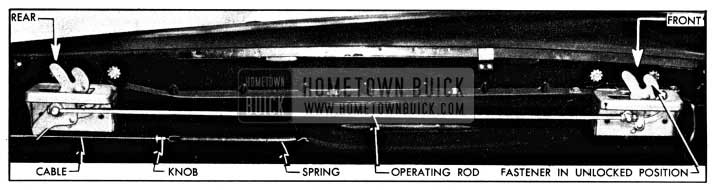
1950 Buick Hood Hinges and Fastener Mechanism-Second Type
Outside Air Ventilator Ducts
A tubular outside air ventilator duct projects through the fender front skirt and is attached to fender rear skirt, on each side of 1950 Buick chassis sheet metal assembly. The screened front end of each ventilator duct takes outside air from behind the grille bars, and the rear end of duct is connected by a flexible hose to an outlet mounted in the side of the cowl front panel. A fly valve located in each outlet is manually operated by a Bowden wire connected to a “VENT” knob on instrument panel.
12-2 1950 BUICK FENDER AND HOOD ALIGNMENT INSPECTION
The hood and front fenders must be aligned with each other on every car to take care of slight variations in form and dimensions of the individual parts. 1950 Buick chassis sheet metal parts stamped in a given set of dies will vary somewhat in form and dimensions due to variations in the hardness of different batches of sheet metal, which causes the stampings to spring in varying amounts when released from the dies.
The hood and front fenders are properly aligned during the installation at the factory; however, some re-adjustment may be required after a car has been shipped or has been in service for some time. This is because sheet metal parts may take a different “set” as a result of vibration and shock incident to shipping or operation during the break-in period. In judging the need for re-adjustment it must be understood that exactly uniform fit and spacing cannot be obtained on all cars of a given model.
IMPORTANT: After any work on front end sheet metal assembly which changes fender position, be sure to check aiming of headlamps as described in paragraph 10-55.
Hood Noises or Panel Flutter
Squeaks or grunting noises in the hood when driving over rough road do not necessarily indicate misalignment of hood and fenders. These noises may be caused by metal contact at some point where clearance should exist or by worn or dry hood bumpers.
If the hood squeaks, check with 1/16″ thick feeler all around the hood for clearance at radiator grille frame, fenders and cowl. If an edge of metal is making contact at any point where clearance should exist a bright metal spot will usually be found. Such spots may be depressed by spring hammering to provide clearance.
A grunting noise in the hood is usually caused by dry rubber bumpers or cowl ledge lacing. Lubricate all rubber bumpers on fender rails and cowl with Lubriplate (Finch Refining Co. No. 110). To correct a persistent case of squeaking or grunting where hood top panel contacts ledge lacing, even when lubricated, cement a l!J.6″ thick strip of felt to panel where the lacing makes contact.
Felt insulating pads should be located between hood top panel and the rear reinforcement on each side just above the bend in reinforcement. If these pads are missing, hood panel flutter may result. Install new pads, using trim cement to hold pads in place. One pad folded double is usually required at each point, but an additional pad may be required to support hood panel and prevent flutter. Do not install too much material or jam it in so tightly that hood panel is bulged upward.
To prevent hood panel flutter, the rear end of hood panel must have firm contact with the rubber lacing attached to cowl ledge. This lacing contains small cylindrical bumpers which have pointed and grooved lower ends to engage in holes in cowl ledge. The bumpers must be securely attached and sealed at the holes in cowl, to prevent leakage of water into front compartment of body.
If cowl ledge lacing is loose, coat cowl and lower side of lacing with weatherstrip cement and let dry until tacky. Press lacing into place and install all bumpers by inserting a small punch with rounded end in holes in top and pressing pointed lower ends of bumpers through holes in cowl until bumpers are held by groove in lower ends.
Preliminary Tightening
Before deciding upon any adjustment to correct hood or fender misalignment it is advisable to check tightness of all attaching screws and bolts, since a true picture of correction requirements cannot be obtained when the sheet metal is loose and free to shift. Check attachments at the following points :
- Radiator mounting strap to mounting bracket on frame.
- Front fender skirts to front ends of frame side rails.
- Fender skirts to grille frame and radiator mounting strap.
- Fender skirts to frame.
- Fenders to grille frame, fender skirts, and supports at cowl.
- Hood hinges to fender rails and hood fasteners (1st type) to hood side rails.
After all parts are properly tightened inspect fender and hood alignment at front doors (subpar. c) and hood alignment (subpar. d) . Make all inspections before performing any adjustments because an adjustment at one point will usually alter alignment at other points. The preliminary inspection should determine the adjustments that will produce the best overall alignment of hood and fenders at all points.
1950 Buick Fender and Hood Alignment at Front Doors
With front doors closed there should be no metal-to-metal contact between doors and rear ends of front fenders. Check for clearance at frequent points, using a strip of fibre or other soft material 1/32″ thick.
The spacing between rear end of front fenders and the shoulder on front edge of doors should be approximately 1/8″, and fairly uniform from top to bottom. The spacing between rear end of
hood and front edge of doors should be fairly uniform on both sides, and sufficient to prevent contact as door is opened.
Before making any adjustment of sheet metal to provide necessary clearance at points mentioned, first make sure that front doors are properly aligned in the body openings as described in paragraph 13-7.
Improper spacing or interference between hood and doors may be corrected by adjustment of hood hinges (par. 12-3).
Improper spacing or interference between front fenders and doors may be corrected by loosening fender attaching bolts at fender supports and rocker panel, which will permit movement of fender in or out, forward or rearward. Fender must not be moved so much that proper alignment of hood is affected.
Where spacing between end of front fender and edge of door is objectionably uneven from top to bottom it may be necessary to adjust the shims under the radiator mounting strap and between fender skirts and frame (par. 12-4).
1950 Buick Hood Alignment Inspection
When closed and locked, the hood should bear firmly against the three rubber bumpers on radiator grille frame and the rubber lacing attached to the cowl ledge. Along the sides, the hood and fender contours should be in reasonably close horizontal alignment. Misalignment at these points may be corrected by vertical adjustment of hood hinges (par. 12-3).
A clearance of approximately 1/8″ should exist between each side of hood and the fender, a:nd the spacing should be fairly uniform from front to rear. Improper spacing along sides of hood may be corrected by lateral adjustment of hood hinges (par. 12-3) .
A clearance of approximately 1/8″ should exist between the rear edge of hood and the shoulder of cowl panel, and the spacing should be fairly uniform from side to side. Improper spacing at this point may be corrected by fore and aft adjustment of hood hinges (par. 12-3). In exceptional cases of uneven spacing it may be necessary to adjust the shims under fender skirts (par. 12-4).
With opposite side of hood locked , raise and lower one side of hood several times to check alignment of pilot pins with holes in pilot plates. If pins are not aligned with pilot holes, the unlocked hinge will bind and tend to raise with the hood. The direction of misalignment may be determined by cleaning grease from pilot pins and holes and coating pins with chalk; a chalked pin will be heavily marked on one side if it is not aligned with pilot hole. A marking on the inner side of pin is not undesirable, provided that unlocked hinge does not bind and raise with the hood. Check opposite side in same manner.
Misalignment of pilot pins with holes may be corrected by adjustment of hood hinges; however, if only the lower end of a pilot pin on hood reinforcement (2nd type) is sprung out of alignment the pin should be straightened instead of adjusting the hinge.
12-3 1950 BUICK HOOD HINGE AND FASTENER ADJUSTMENTS
Adjustment of First Type Hood Hinges and Fasteners
The first type hood hinge has a key operated fastener. The hinge mounting bracket has horizontally slotted bolt holes which permit fore and aft adjustment on the fender rail. The bolt holes in fender rail are vertically slotted to permit vertical adjustment of hinge. When hinge attaching bolts are loosened the hinge may be moved in either direction therefore care must be used to move hinge only in the direction required.
When lowering a hinge it may be necessary to bend up the ends of the bumper located on the under side of the hinge plate. When raising a hinge it may be necessary to bend down the ends of bumper. The bumper should be adjusted so that the hinge plate is leveled, thereby permitting the hood fastener rod to properly engage the hooks on hinge plate.
A slight lateral adjustment of a hinge to change hood-to-fender clearance may be made by carefully bending the hinge in required direction. To adjust a hinge inward to increase clearance, insert a flat bar between fender rail and hinge plate and bend hinge slightly inward as shown in figure 12-2, view A.
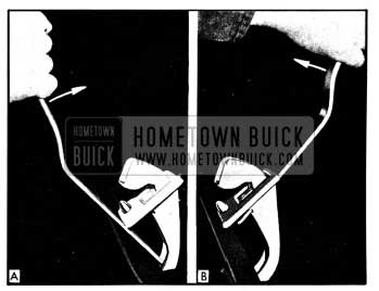
1950 Buick Bending Hood Hinges
To adjust a hinge outward to decrease clearance, insert a bar through opening in hinge under the plate and bend hinge slightly outward as shown in figure 12-2, view B. When bending hinge outward remember that a light contact on inner side of pilot pin is permissible but pin must not bind in pilot hole.
In some cases it may be necessary to laterally adjust a hinge farther than it is advisable to bend the hinge. This may be done by means of spacer washers placed between the hinge and the fender rail at attaching bolts. U-shaped spacer washers which can be removed or installed without removing hinge bolts are furnished under Group 8.014 in thickness of .030″, .060″ and .120″. Adding washers moves hinge outward and removing washers moves hinge inward. An equal total thickness of washers must be used at each hinge bolt.
In exceptional cases where sheet metal parts have been distorted by accident it may be necessary to alter the width of hood to obtain proper side spacing (subpar. c, below).
After hood hinge adjustment has been completed, check hood to see that proper locking and hood fastener tension exists. This can be checked by lifting on nose of hood above the radiator grille frame, also by operating the hood fastener with key. Any looseness of hood, or exceptionally hard operation of fastener, indicates the need for fastener tension adjustment.
If fastener tension adjustment is indicated, first check the fastener rod clips to make sure they are tight. Raise one side of hood, with opposite side locked, and inspect contact between hinge plates and hood reinforcement pilot plates on the locked side under the hood. Both hinge plates should be in full contact with reinforcement pilot plates. Check opposite side in the same manner.
If hinge plates do not properly contact pilot plates, first check the hinge plates with straight edge to see if they are flat. See figure 12-3, view A.
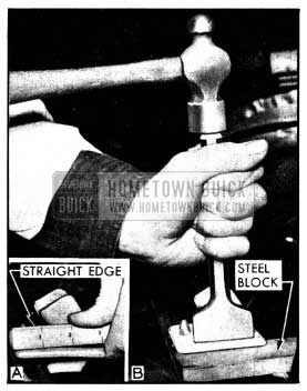
1950 Buick Checking and Straightening Hinge Plate
If plates are not flat, straighten them with a suitable punch and hammer while supporting plate on a flat steel block. See figure 12-3, view B. Check the pilot plates on hood panel reinforcements and straighten them with a pry bar or hammer if they are distorted. Bend pilot plate down a trifle along inner edge of opening as shown in figure 12-4 to obtain contact along inner edge, if necessary.
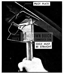
1950 Buick Bending Edge of Pilot Plate
Make sure that bent down edge is straight and not curved (fore and aft) to insure contact with hinge plate.
If the fastener rod does not have proper tension loosen the rod clip attaching bolts and move rod up to increase tension or down to decrease tension as required. The bolt holes in clip may be slotted with a round file if they do not permit sufficient movement of fastener rod to obtain proper tension. For minor adjustment to increase tension it is permissible to bend down the two hooks on each hinge, using care to avoid distorting or otherwise damaging the hinge and making sure that both hooks have equal contact with the rod. It is not advisable to bend the hooks up to decrease tension because the rod may not reach a securely locked position under the hooks.
Adjustment of Second Type Hood Hinges and Fasteners
The second type hood hinge has a cable operated fastener. The hinge mounting bracket has horizontally slotted bolt holes which permit fore and aft adjustment on the fender rail. Bolt holes in fender rail are not slotted for adjustment of hinge in any direction, therefore the vertical setting of hinge is not affected when hinge bolts are loosened.
The hinge fastener and housing assembly is bolted to the gooseneck hinge strap and the bolt holes in strap are slotted to permit vertical adjustment of the fastener housing only. See figure 12-5.
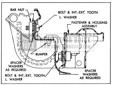
1950 Buick Hood Hinge Mounting-Second Type
This arrangement permits vertical adjustment without changing the pivot point of the hinge, and without changing the fore and aft setting.
Lateral adjustment of hinge to change hoodto-fender clearance is obtained by U-shaped spacer washers which can be removed or installed without removing hinge bolts. These washers are furnished under Group 8.014 in thicknesses of .030″, .060″ and .120″.
To move hinge fastener and housing assembly outward to decrease hood-to-fender clearance, either remove spacer washers from between fastener housing and hinge strap or install washers between hinge mounting bracket and fender rail. To move parts inward to increase clearance, either remove spacer washers from between hinge mounting bracket and fender rail or install washers between hinge strap and fastener housing. See figure 12-5. An equal total thickness of washers must be used on both bolts at either point of adjustment.
When adjusting hinges it is important to keep all four pilot plates level and on a common plane. Use a straight edge to check for level between front and rear hinge pilot plates on each side and readjust hinges as required to obtain full bearing of both plates against straight edge.
A rubber bumper is mounted in fender rail under the upper inner end of the hinge strap. Make sure that this bumper is in place and is in good condition. If this end of hinge strap is bent so that the hinge pilot plate is not level, laterally, carefully bend the strap to level up the pilot plate.
The hood fastener tension is non-adjustable as the latches are spring loaded to make them automatically seek a firmly locked position. After adjustment or replacement of a hood hinge the adjustment of the hood fastener operating rod should be checked. Push both fasteners down to the locked position and have both hinges resting on bumpers on fender rail. Check the clearance between the shoulder on rear end of operating rod and the trunnion of rear fastener; clearance should be approximately 3/32″. Adjust the nuts on each side of front fastener trunnion to obtain this clearance, if necessary. See figure 12-6.
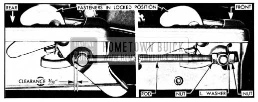
1950 Buick Adjustment of Hood Fastener Operating Rod
Whenever it becomes necessary to remove the hood fastener control cable, disconnect the return spring, pull control knob out and remove it from cable end by unscrewing the fluted head set screw in knob. After removal of control knob the cable assembly can readily be removed by disconnecting at bracket clamp and pulling it forward through arm of rear hinge fastener.
Adjustment of Hood Width
The hood panel reinforcements are of channel section and welded to hood side rails to provide an assembly of fixed width at all points. Adjustment for width should not be necessary except when hood has been distorted due to accident. If alteration of hood width becomes necessary, however, it may be accomplished by carefully bending the reinforcements with proper tools.
The hood may be made wider by straightening the reinforcement with a C-clamp prepared and applied as shown in figure 12-7.
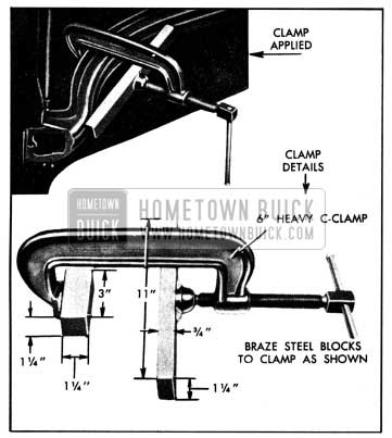
1950 Buick Straightening Hood Panel Reinforcement to Spread Hood
The hood may be reduced in width by bending the reinforcement with a large turnbuckle prepared and applied as shown in figure 12-8. Both tools illustrated may be made locally from details shown.
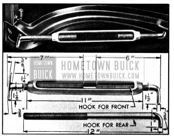
1950 Buick Bending Hood Panel Reinforcement to Reduce Hood Width
Fitting Hood Hinges to New Fenders
The change in hood hinge design required a change in fender rails, but since the fender rails can easily be reworked to accommodate either type hinge no change was made in fender part number.
If a second type fender is installed on a car having the first type hood hinges it may be necessary to slot the bolt holes in fender rail to permit vertical adjustment of hood hinges. The holes should be slotted vertically only, using a round file of proper size.
If a first type fender is installed on a car having the second type hood hinges, drill a 5/16″ hole and cut away the fender rail at each hinge location as shown in figure 12-9.
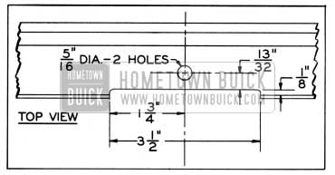
1950 Buick Alteration of First Type Fender Rail for Second Type Hinge
Install a rubber bumper in each 5/16″ hole, and bolt hinges in position at top of slotted bolt holes in fender rail.
12-4 RADIATOR MOUNTING STRAP AND FRONT FENDER SKIRT MOUNTING ADJUSTMENTS
If the front end of the sheet metal assembly is too high or too low, resulting in objectionably unequal vertical spacing between front fenders and doors, it will be necessary to change the shims located under the radiator mounting strap and the fender skirts. If the front end of sheet metal assembly is tilted to right or left so that proper alignment of hood and fenders cannot be obtained by adjustment, it will be necessary to change shims under the fender skirts. These shimming adjustments should only be necessary to offset misalignment resulting from an accident.
Under normal conditions, steelbestos shims having a total thickness of 11/32″ are placed between the radiator mounting strap and the mounting bracket on the frame. This thickness is obtained by using two shim assemblies consisting of three .056″ shims stapled together. The total thickness may be changed as required by adding or removing single shims. When the total thickness required exceeds 1/2″, however, a steel shim .180″ thick is placed next to the mounting bracket to keep the total build up of steelbestos shims to 1/2″ or less.
Excessive shimming under radiator mounting strap should be avoided as the stability of the front end sheet metal assembly will be affected. Reduction in shim thickness below l 11/32″ must be made with caution, unless the reduction is caused by the bracket on frame being too high. If reduction is due to other causes there is danger of interference between engine fan and radiator inlet hose, also reduction of necessary clearances between the sheet metal parts and chassis.
At the point where each front fender skirt is attached to the frame front end a rubber shim is placed on each side of the frame rail top flange, with a steel washer, 1/8″ steel shim and tubular spacer placed to control compression of the rubber shims as the bolt is tightened. Two steelbestos shims are placed between the 1/8″ steel shim and the fender skirt. When additional shimming is required one or more extra steel shims .060″ thick are placed between the steelbestos shims and the fender skirt. See figure 12-10.
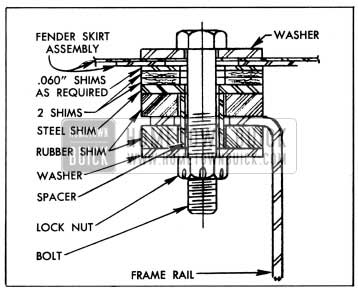
1950 Buick Fender Skirt Bolt and Shims
Correct thickness of extra steel shims at each fender skirt mounting is determined after proper shimming of radiator mounting strap has been established. The extra shims should be installed as required to level up the sheet metal as viewed from in front of car. It is not necessary to have an equal number of extra shims at both mountings as some variation in sheet metal may exist. Improper leveling at this point may result in poor hood fits as well as noticeably unequal spacing between bumper guards and grille frame or between bumper face plate and bumper back bar shields.
When unequal spacing exists between bumper guards and grille frame or between bumper face plate and back bar shields it is advisable to check the front bumper before changing shims under the fender skirts. Make sure that bumper back bars are not bent so as to throw bumper out of level. Loosen back bar to frame bolts, jack up bumper bar on each side and tighten bolts securely; this will take up play in bumper bolt holes in the same direction on both sides.
Leave A Comment
You must be logged in to post a comment.