SECTION 10-H 1950 BUICK SIGNAL SYSTEMS
10-58 1950 BUICK STOP LIGHTS AND SWITCH
The stop lights are incorporated in the combination tail, stop, and direction signal lamps. These lamps and the replacement of bulbs are covered in paragraph 10-56.
The stop lights are controlled by a hydraulic switch mounted on the brake pipe distributor fitting near the master cylinder. The switch is closed by hydraulic pressure when the brakes are applied. It requires no adjustment or attention except to make sure that the wire connections are tight and that the switch is tightly screwed into the distributor fitting to avoid fluid leaks that would affect operation of the brakes.
The stop lights are independent of the lighting switch. The stop light circuit is protected by the 14 ampere “Direction Signal” fuse mounted on the fuse block under the cowl.
Replacement of 1950 Buick Stop Light Switch
When replacing stop light switch have new switch ready to install as soon as old switch is removed from distributor fitting. Before installing new switch make sure that port in distributor fitting is filled with brake fluid. Have a helper gently depress brake pedal to fill the fitting from master cylinder, if necessary, then immediately install new switch.
If brake pedal has springy, spongy action after installation of stop light switch, air has entered brake pipes and it will be necessary to bleed the hydraulic system (par. 8-9).
10-59 1950 BUICK HORNS, RELAY AND BUTTON
1950 Buick Horns and Relay
Two Delco-Remy electrically operated vibrator type horns are mounted on the radiator mounting strap. Both horns are operated simultaneously by a horn relay mounted on radiator mounting strap; the relay is controlled by the horn button on steering wheel.
The left hand horn is high pitched (380-400 cycles) and the right hand horn is low pitched (302-323 cycles), so that together they produce a pleasing blended tone. The horns have been made exceptionally compact by a spiral air column cast into the base and collar. See figure 10-95.
1950 Buick Horn Contact Point Adjustment
The horn relay is an electrical switch which closes the circuit between the battery and the horns when the horn button is pressed, and opens the circuit when the button is released. The relay permits control of the horns with a small amount of current passing through the horn button contacts. The high current required by the horns would cause arcing and burning of these contacts.
When the horn button contacts are closed, a small amount of current flows through the relay winding to ground at the horn button. This magnetizes the relay core, which attracts the fiat steel relay armature. The armature has a contact point which makes contact with a stationary point to close the horn circuit. When horn button is released, current stops flowing through relay winding so that the core loses its magnetism ; the armature spring then causes contact points to be separated.
1950 Buick Horn Button – Flexible Spoke Steering Wheel
The horn button used with the flexible spoke steering wheel includes an operating ring and a contact plate mounted in the steering wheel cap base. A spring holds the wire connection against the center of the contact plate which is insulated from the wheel cap base. When the operating ring is pressed it touches the contact plate to close the circuit to ground, thus completing the relay circuit and causing the horns to operate. Springs cause the operating ring to move away from the contact plate and open the relay circuit when the operating ring is released. See figure 10-93.
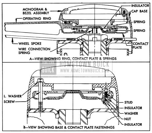
1950 Buick Horn Button In Flexible Spoke Steering Wheel- Sectional View
The monogram and bezel assembly is held in the steering wheel cap base by three springs. The assembly may be removed by inserting a small screw driver in a notch provided in the cap b se and prying against the bezel. When the monogram and bezel assembly are removed, the operating ring and wheel base assembly may be removed by removing the three screws which attach the wheel base to the steering wheel hub. See figure 10-93.
1950 Buick Horn Button – Solid Spoke Steering Wheel
The horn button assembly used in the solid spoke steering wheel consists of a horn button cap with contact strap, a contact cup, a horn blowing spring, a contact plate, and attaching screws with insulating fibre spacer bushings.
The horn button cap has a rubber retainer which snaps over the rim of the contact cup and the contact strap bridges between the horn wire connector in steering shaft and the rim of contact cup. The contact cup is attached to steering wheel hub by three screws and insulating fibre spacer bushings which permit movement of the cup when button cap is pressed. The screws and bushings hold the flat steel contact plate tight against the wheel hub. The dished steel horn blowing spring is placed between the cup and contact plate, with outer rim of spring resting on a shoulder of the plastic material of wheel, which provides insulation. See figure 10-94.
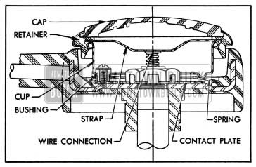
1950 Buick Horn Button Parts In Solid Spoke Steering Wheel
Normally, the dished spring holds the contact cup outward so that no contact is made, but when the cap is pressed the cup pushes the raised inner edge of the spring down into contact with the plate, thereby completing a grounding connection between the horn wire connector and the steering shaft.
Whenever horn button parts are assembled into the steering wheel the dished horn blowing spring must be installed so that clearance exists between inner edge of spring and the contact plate. See figure 10-94. The contact cup must be installed with the locating notch in rim in line with lower spoke of steering wheel so that the horn button cap emblem will be properly located when cap is installed.
10-60 ADJUSTMENT OF 1950 BUICK HORNS
When horns fail to blow first check wiring circuit (par. 10-12, c) before attempting to adjust horns. If horns are at fault, or tone is poor, adjust each horn for specified current draw as follows:
- Remove horn from car and remove the back shell, which is crimped over the collar at four points.
- Inspect air gap between armature and core for steel burrs or other foreign matter ; clean out if present. This may correct the trouble. If it does not, proceed as follows:
- Connect an ammeter in series with the horn and a fully charged 6-volt battery to measure the current draw when horn blows. Current draw should be as follows:
- Left (high note) horn – 16 to 18 amperes
- Right (low note) horn – 17 to 19 amperes
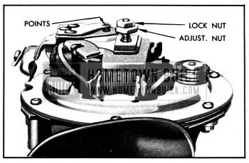
- Adjust to specified current draw, if necessary, by loosening lock nut and turning contact point adjusting nut clockwise to decrease or counterclockwise to increase current draw. See figure 10-95. This adjustment is very sensitive, and adjusting nut should not be moved more than one-tenth turn at a time, then locked with nut each time before trying the horn.
Increasing the current draw increases the horn volume. Too much current will produce a Figure 10-95-Hom Contact Point Adjustment high cut-in voltage, which will cause a sputtering sound and may cause horn to stick in cold weather.
- After each horn has been adjusted individually, sound both horns together to check for proper blend of tone.
- After horn adjustment is completed install the back shell. Make sure that back shell is seated against horn collar all around, then crimp tangs of shell over collar at four points.
- When horns are reinstalled, connect a voltmeter between each horn terminal and ground to check voltage when horns are blown. Voltage at each horn should be at least 5.25.
10-61 ADJUSTMENT OF 1950 BUICK HORN RELAY
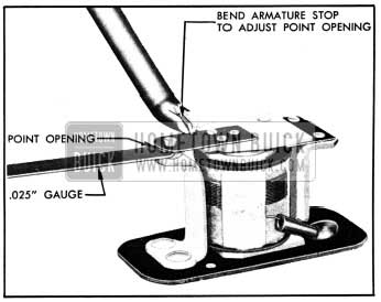
Three checks and adjustments are required on the horn relay: air gap, point opening, and closing voltage. These should be made in the following order:
- Remove horn relay from car then remove relay cover.
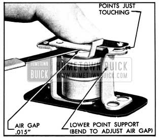
- Push relay armature down until contact points just touch, then check air gap between armature and end of core using feeler gauges. Air gap should be .015″. Adjust gap to .015″, if necessary, by bending the lower point support. See figure 10-96.
1950 Buick Horn Contact Point Adjustments
1950 Buick Relay Contact Point Adjustment
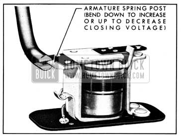
1950 Buick Adjustment of Horn Relay Closing Voltage
10-62 1950 BUICK DIRECTION SIGNAL LAMPS AND SWITCH
1950 Buick Direction Signal Lamps and Indicators
The 1950 Buick directional signal lamps are incorporated in the front parking lamps and the rear combination tail, stop and signal lamps.
Each front parking lamp contains a 21-3 CP lamp bulb; the 3 CP bulb filament is used for parking and the 21 CP bulb filament is used for the directional-signal light. Each rear lamp contains a separate 21 CP lamp bulb for the direction signal light, which operates independently of the tail and stop lights.
When the ignition switch is turned on and the direction signal switch is manually operated to indicate a turn, the front and rear signal lights flash on and off on the side of car for which a turn is indicated. The flashing of signal lights is caused by a Tungsol flasher which is connected into the proper signal light circuit by contacts made in the direction signal switch when switch is set for a turn.
When the direction signal lights are flashing, a signal indicator bulb on instrument panel also flashes, producing a small arrow of green light to indicate the direction for which the signal has been set. For a left turn the green light flashes in the left side of the charge indicator, and for a right turn the green light flashes in the right side of the gasoline gauge.
1950 Buick Direction Signal Switch Operation
The direction signal switch and its operating mechanism is enclosed in a housing on steering column just below steering wheel.
The switch must be manually set by moving switch control lever down to indicate a right turn or moving lever up to indicate a left turn.
The switch is automatically returned to “off” position when steering wheel is straightened after completion of a turn. It can be manually returned to “off” position if the turn is not made. If switch is set to indicate a turn in one direction and a turn is made in opposite direction, the switch will be returned to “off” position as the turn is made and will not give a signal for the turn actually made.
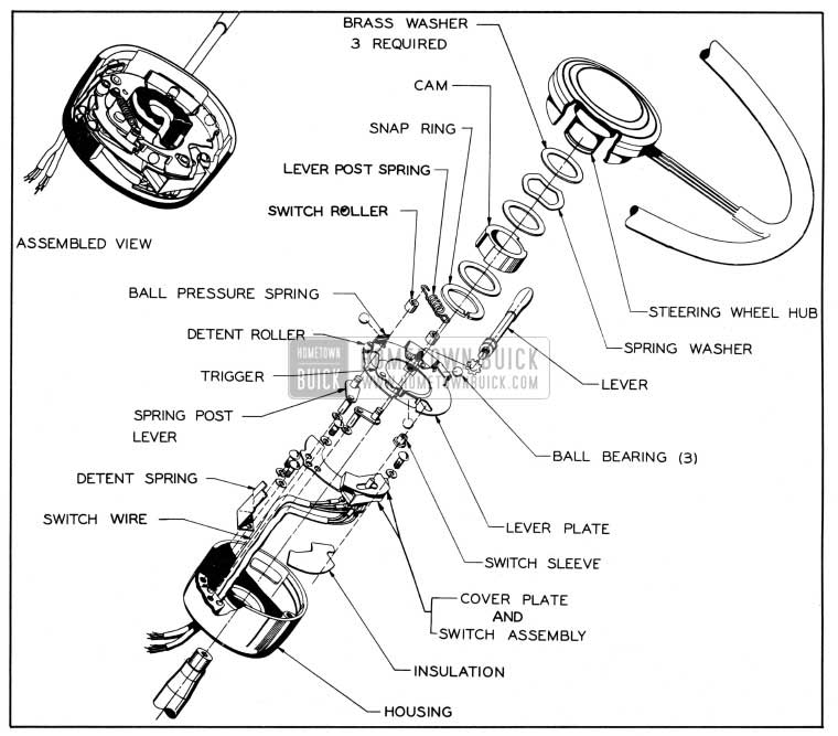
The switch is attached to a cover plate mounted in the switch housing. The switch handle, protected by a hardened steel sleeve, extends upward to engage a slotted hole in the lever plate which is mounted in housing on three ball bearings so that it can be rotated by the attached control lever. Rotation of the lever plate moves the switch handle to obtain the “left”, “off”, or “right” position of switch contacts. The lever plate is held in the selected position by a detent roller on the plate which engages a detent spring mounted in switch housing. See figure 10-103.
When the lever plate is manually rotated for a right (or left) turn by the control lever, the corresponding end of a trigger on lever plate is pressed against a cam on the steering wheel hub by the action of a spring loaded post lever. When the steering wheel is turned approximately one third revolution for a right (or left) turn, the end of the trigger drops into a notch in the cam so that the trigger, lever plate, and switch handle are pushed back to the “off” position as the wheel is turned in the opposite direction after the turn is completed. As the switch reaches the “off” position, the trigger is withdrawn from engagement with the cam by the action of another spring loaded post lever. See figure 10-103. The switch remains in the “off” position until it is again set for a turn.
The cam is a hardened steel ring with two diametrically opposite elongated notches. It is installed on the shouldered hub of steering wheel with three brass washers and a spring washer, all being retained by a snap ring. The brass washers and spring washer from a friction clutch which facilitates shifting of the cam to adjust switch for proper timing, and coincidentally prevents accidental locking or jamming of the steering wheel by the signal switch mechanism.
1950 Buick Direction Signal Lamp Circuits
Since the direction signal lights are independent of the headlamp lighting switch and thermo circuit breaker, the wiring circuits are protected by a “Direction Signal” fuse on the fuse block under the cowl. The Tungsol flasher is also mounted on the fuse block, which serves as a terminal block between the signal switch and the chassis wiring.
The direction signal lights are independent of the parking and stop light circuits, and the indicator lamp bulb sockets are grounded to the instrument panel.
Figures 10-99, 10-100, and 10-101 show the direction signal circuits when signal switch is set for No Turn, Right Turn, and Left Turn. Direction signal switch wiring is also shown in the chassis wiring circuit diagrams in Section 10-J.
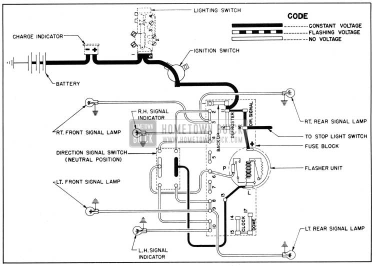
1950 Buick Direction Signal Lamp Circuit Diagram, No Turn Indicated
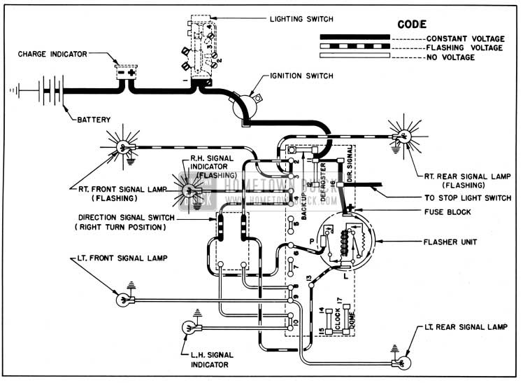
1950 Buick Direction Signal Lamp Circuit Diagram, Right Turn Indicated
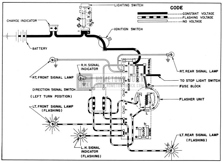
1950 Buick Direction Signal Lamp Circuit Diagram, Left Turn Indicated
10-63 TIMING ADJUSTMENT OF 1950 BUICK SIGNAL SWITCH CAM
If the direction signal switch cam is correctly located on the hub of steering wheel, the switch
ill automatically return to the “off” position following a turn, provided that the steering wheel has been turned at least one-third revolution. If the wheel has been turned less than one third revolution, the switch must be manually returned to the “off” position.
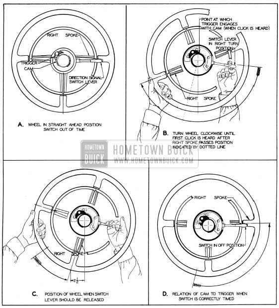
The actual returning of switch to the “off” position takes place as the steering wheel returns to the straight-ahead position. If the switch does not operate as described, the switch cam is not in proper relation to the trigger. See figure 10-102, view A.
1950 Buick Timing of Direction Signal Switch Cam
The switch cam may be adjusted for correct timing as follows:
- Make certain that steering wheel is installed on steering shaft so that the lower spoke is straight down when front wheels are in straight-ahead position.
- Move switch control lever down to indicate a right turn, then rotate steering wheel clockwise until click is heard as the switch trigger drops into a notch in the cam, or a slight movement of control lever is felt. The steering wheel should have been turned at least one-third revolution at this point. See figure 10-102, view B.
- Hold control lever down firmly and slowly turn steering wheel counterclockwise until the right horizontal spoke is approximately 2 1/2″ to the left of the straight-down position. This will cause the cam to slip in its friction mounting on the steering wheel hub. See figure 10-102, view C.
- Release hold on control lever and turn steering wheel to straight-ahead position. The switch will automatically return to “off” position as the wheel is turned. No further adjustment is required for a left turn. See figure 10-102, view D.
- The clutch friction for maintaining the 1950 Buick signal switch cam in the correct position on steering wheel hub is controlled by a crimped steel spring washer. See figure 10-103.
1950 Buick Direction Signal Switch-Disassembled
If trouble is experienced in maintaining proper timing and adjustment of the cam, the spring washer is probably flattened and too weak, permitting the cam to turn on hub. To check the clutch friction, note the pressure required to hold the control lever while slipping the cam in step 3 above. Compare with another car on which no trouble is experienced. See paragraph 10-64 for replacement of cam or clutch friction parts.
10-64 REPLACEMENT OF 1950 BUICK SIGNAL SWITCH PARTS
Replacement of 1950 Buick Signal Switch Cam or Spring Washer
- Set direction signal switch in “off” position and remove steering wheel (par. 7-6).
- Remove snap ring, cam, and washers from steering wheel hub.
- Before installation of parts check spring washer for proper tension. A pressure of 125 to 150 pounds should be required to compress washer to 1/8″ height. Make sure that brass washers are in good condition, or install new ones.
- Install cam and washers on steering wheel hub in the following order: brass washer, spring washer, brass washer, cam, brass washer, and snap ring. See figure 10-103. CAUTION: Use care when installing parts to avoid distorting and weakening the spring washer.
- Install steering wheel (par. 7-6) and set the timing of signal switch cam (par. 10-63).
Replacement of 1950 Buick Signal Switch
- Disconnect signal switch wires from fuse block under the cowl.
- Set direction signal switch in “off” position and remove steering wheel (par. 7-6).
- Remove switch control lever and lock washer from lever plate.
- Remove lever post springs and remove switch rollers from spring post levers.
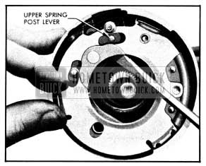
- Pry outward on the plate guides far enough to permit removal of the lever plate. Using a screwdriver to pry, remove ball bearing “A” (opposite lever), then bearing “B”, and finally bearing “C.” See figure 10-104.
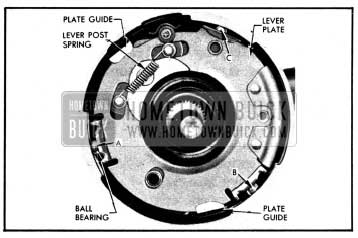
1950 Buick Signal Switch Lever Plate
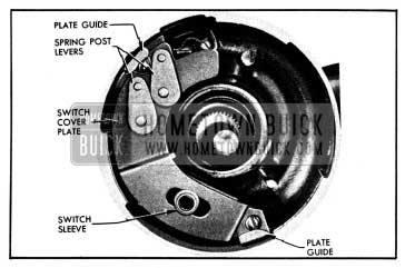
1950 Buick Spring Post Levers, Plate Guides, Sleeve, Switch Cover Plate
1950 Buick Installing Lever Plate
Leave A Comment
You must be logged in to post a comment.