SECTION 2-E 1950 BUICK REPLACEMENT OF ENGINE PARTS LIKE CRANKSHAFT AND CONNECTING ROD BEARINGS, PISTONS AND RINGS
2-21 REPLACEMENT OF CONNECTING ROD BEARINGS
A connecting rod bearing consists of two halves or shells which are alike and interchangeable in rod and cap. When the shells are placed in rod and cap the ends extend slightly beyond the parting surfaces so that when rod bolts are tightened the shells will be clamped tightly in place to insure positive seating and to prevent turning. The ends of shells must never be filed flush with parting surface of rod or cap.
If a precision type connecting rod bearing becomes noisy or is worn so that clearance on crankpin is excessive, a new bearing of proper size must be selected and installed since no provision is made for adjustment. Under no circumstances should the connecting rod or cap be filed to adjust the bearing clearance.
Inspection of Connecting Rod Bearings and Crankpin Journals
After removal of lower crankcase, disconnect two connecting rods at a time from crankshaft and inspect the bearings and crankpin journals. While turning crankshaft it is necessary to temporarily reconnect the rods to crankshaft to avoid possibility of damaging the journals through contact with loose rods.
If connecting rod bearings are chipped or scored they should be replaced. If bearings are in good physical condition check for proper clearance on crankpins as described in subparagraph b, below.
If crankpin journals are scored or ridged the crankshaft must be replaced, or reground for undersize bearings, to insure satisfactory life of connecting rod bearings. Slight roughness may be polished out with fine grit polishing cloth thoroughly wetted with engine oil. Burrs may be honed off with a fine oil stone.
Use an outside micrometer to check crankpins for out-of-round. If crankpins are more than .0015″ out of round, a proper adjustment of connecting rod bearings or satisfactory life of new bearings cannot be expected.
Checking Clearance and Selecting Replacement Bearings
Service bearings are furnished in standard size and several undersizes, including undersizes for reground crankshafts.
The clearance of connecting rod (and crankshaft) bearings may be checked by use of Plastigage, Type PG-1 (green), which has a range of .001″ to .003″. Plastigage is manufactured by Perfect Circle Corporation, Hagerstown, Indiana, and is available through Buick parts warehouses under Group 0.093.
- Remove connecting rod cap and wipe oil from bearing and crankpin journal, also blow oil out of hole in crankshaft. NOTE: Plastigage is soluble in oil.
- Turn crankshaft so that crankpin being checked is approximately 30 degrees before bottom dead center. In this position the clearance will be checked at point of least clearance if crankpin is worn out of round, and the Plastigage will not be at oil hole in crankshaft.
- Place a piece of Plastigage lengthwise along the bottom center of the lower bearing shell (fig. 2-24, view A), then install cap. Tighten bolts to 40-50 ft. lbs. torque on Series 40-50 engine, or to 60-65 ft. lbs. torque on Series 70 engine. NOTE: A ridge formed on edge of cap and a boss formed on web of rod above the bearing must be in line and toward rear of engine when cap is installed.
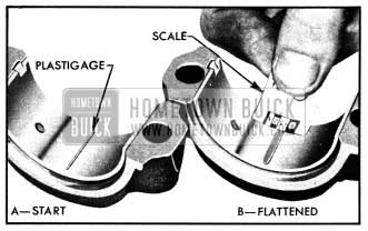
1950 Buick Checking Bearing Clearance with Plastigage
- DO NOT TURN CRANKSHAFT with Plastigage in bearing.
- Remove bearing cap. The flattened Plastigage will be found adhering to either the bearing shell or the crankshaft. Do not remove it.
- Using the scale printed on the Plastigage envelope, measure the width of the flattened Plastigage at its widest point. The number within the graduation which most closely corresponds to the width of Plastigage indicates the bearing clearance in thousandths of an inch. See figure 2-24, View B.
- The desired clearance with a new bearing is .0008″ to .0015″. If bearing has been in service it is advisable to install a new bearing if the clearance exceeds .022″; however, if bearing is in good condition and is not being checked because of bearing noise, it is not necessary to replace the bearing.
- If a new bearing is being selected, try a standard size, then each undersize bearing in turn until one is found that is within the specified limits when checked for clearance with Plastigage. NOTE: Each undersize bearing shell has a number stamped on outer surface on or near the tang to indicate amount of undersize.
- After the proper size bearing has been selected, clean off the Plastigage, oil the bearing thoroughly and reinstall cap. Tighten connecting rod bolts to 40-50 ft. lbs. torque on Series 40-50 engine, or to 60-65 ft. lbs. torque on Series 70 engine. Tighten Pal-nuts just enough to lock securely.
- With selected bearing installed and bolts tightened, it should be possible to move connecting rod freely back and forth on crankpin as allowed by end clearance. If rod cannot be moved, either the bearing is too much undersize or a misaligned rod is indicated.
2-22 REPLACEMENT OF CRANKSHAFT BEARINGS
Crankshaft bearings are the precision type which do not require reaming to size or other fitting. Shims are not provided for adjustment since worn bearings are readily replaced with new bearings of proper size. Bearings for service replacement are furnished in standard size and several undersizes, including undersizes for reground crankshafts.
Under no circumstances should crankshaft bearing caps be filed to adjust for wear in old bearings.
A crankshaft bearing consists of an upper and a lower half or shell. In Series 50 engines the upper and lower shells are interchangeable. In Series 40 and 70 engines the shells are not interchangeable since the lower shell has a short oil groove and the upper shell has full length oil groove across the middle, and an oil hole. When the shells are placed in crankcase and bearing cap the ends extend slightly beyond the parting surfaces so that when cap bolts are tightened the shells will be clamped tightly in place to insure positive seating, and to prevent turning. The ends of shells must never be filed flush with parting surface of crankcase or bearing cap.
Inspection of Crankshaft Bearings and Crankshaft
After removal of lower crankcase, oil pump and flywheel lower housing (syncro-mesh) or bell housing cover (Dynaflow) perform the following removal, inspection and installation operations on each crankshaft bearing in turn so that the crankshaft will be well supported by the other bearings.
- Since any service condition which affects the crankshaft bearings may also affect the connecting rod bearings, it is advisable to inspect connecting rod bearings first (par. 2-21). If crankpins are worn to the extent that crankshaft should be replaced or reground, replacement of crankshaft bearings only will not be satisfactory.
- Remove one bearing cap, then clean and inspect lower bearing shell and the crankshaft journal. If journal surface is scored or ridged, the crankshaft must be replaced or reground to insure satisfactory operation with new bearings. Slight roughness may be polished out with fine grit polishing cloth thoroughly wetted with engine oil, and burrs may be honed off with a fine stone.
- If condition of lower bearing shell and crankshaft journal is satisfactory, check the bearing clearance with Plastigage as described for connecting rod bearings in paragraph 2-21.
- When checking a crankshaft bearing with Plastigage, turn crankshaft so that oil hole is up to avoid dripping of oil on Plastigage. Place paper shims in bearing caps of adjacent bearings and tighten cap bolts to take the weight of crankshaft off the lower shell of bearing being checked. NOTE: Arrow on cap must point to front of engine.
- If the bearing clearance exceeds .002″, it is advisable to install a new bearing; however, if bearing is in good condition and is not being checked because of bearing noise, it is not necessary to replace the bearing.
Selection and Installation of a New Crankshaft Bearing
- Loosen all crankshaft bearing cap bolts 1f2 turn, and remove cap of bearing to be replaced.
- Remove upper bearing shell by inserting a suitable tool in crankshaft oil hole and turning crankshaft to push shell out. Tools for this purpose are available through automotive jobbers. If a tool is not available, a 1/8″ x 1 1/2″ cotter pin with ends bent to lie flat against crankshaft journal may be used. CAUTION: When turning crankshaft with rear bearing cap removed hold oil seal to prevent it from rotating out of position in crankcase.
- The crankshaft journal cannot be measured with an outside micrometer when shaft is in place; however, when upper bearing shell is removed the journal may be checked for out-of round by using a special crankshaft caliper and inside micrometer. The caliper should not be applied to journal in line with the oil hole.
If crankshaft journal is more than .0015″ out-of-round, the crankshaft should be replaced or reground for undersize bearings since the full mileage cannot be expected from bearings used with an excessively out-of-round crankshaft.
- Before installation of bearing shells make sure that crankshaft journal and bearing seats in crankcase and cap are thoroughly cleaned.
- Coat inside surface of upper bearing shell (full length oil groove in Ser. 40-70) with engine oil and place shell against crankshaft journal so that tang on shell will engage notch in crankcase when shell is rotated into place.
- Rotate bearing shell into place as far as possible by hand, then insert suitable tool in crankshaft oil hole and rotate crankshaft to push shell into place. CAUTION: Bearing shell should move into place with very little pressure. If heavy pressure is required, shell was not started squarely and will be distorted if forced into place.
- Place lower bearing shell (short oil groove in Ser. 40-70) in bearing cap, then check clearance with Plastigage as previously described.
- The desired clearance with a new bearing is .0008″ to .0015″. If this clearance cannot be obtained with a standard size bearing, insert an undersize bearing and check clearance again with Plastigage. NOTE: Each undersize bearing shell has a number stamped on outer surface on or near the tang to indicate amount of undersize.
- When the proper size bearing has been selected; clean out all Plastigage, oil the lower shell and reinstall bearing cap. Tighten cap bolts to 90-100 ft. lbs. torque. The crankshaft should turn freely at flywheel rim; however, a very slight drag is permissible if an undersize bearing is used.
- After bearing is installed and tested, loosen all bearing cap bolts 1/2 turn and continue with other bearings. When all bearings have been installed and tested, tighten all bearing cap bolts to 90-100 ft.lbs. torque.
Installation of Rear Bearing Oil Seals
The rear crankshaft bearing is sealed against external leakage of oil in the following manner:
- An oil slinger machined on the crankshaft rotates in a groove formed in crankcase and bearing cap just to rear of the rear crankshaft bearing. This oil collecting groove drains back into the crankcase.
- Braided fabric seals are pressed into grooves formed in crankcase and bearing cap to rear of the oil collecting groove. See figure 2-25.
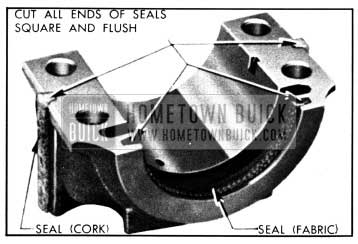
1950 Buick Rear Bearing Oil Seals
- Cork seals are located at the vertical joints between the bearing cap- and the crankcase.
The braided fabric seal can be installed in crankcase only when crankshaft is removed; however, the seal can be replaced in cap whenever cap is removed. Remove old seal and place new seal in groove with both ends projecting above parting surface of cap. Force seal into groove by rubbing down with hammer handle or smooth wood stick until seal projects above the groove not more than 1/16″. Cut ends off flush with surface of cap, using sharp knife or razor blade. See figure 2-25. CAUTION: The engine must be operated at slow speed when first started after new braided seal is installed.
The cork seals are slightly longer than grooves in bearing cap. Coat grooves with gasket cement and when this is tacky carefully work seals into grooves with a putty knife. Lightly compress seals into grooves by placing cap in a vise for a few minutes. Cut ends of seals square and flush with machined surfaces of bearing cap and coat outer surfaces with vaseline before installing cap ir crankcase.
Installation of Oil Pump and Lower Crankcase
- Install oil pump, following procedure given in paragraph 2-30 to avoid binding.
- Thoroughly clean lower crankcase and flywheel lower housing or bell housing cover before installation. Use new gaskets when installing lower crankcase and flywheel lower housing.
- When connecting steering tie rod to pitman arm be careful to properly seat the bearings around ball stud. Make sure that the pressed steel dust cover properly covers opening around ball stud. Turn tie rod plug up solid then back off two turns and install cotter pin.
2-23 REPLACEMENT OF PISTONS, RINGS, AND CONNECTING RODS
Removal and Disassembly of Piston and Rod Assemblies
- Remove cylinder head (par. 2-16), disconnect tie rod from pitman arm and remove lower crankcase, remove oil pump.
- Examine the cylinder bore above the ring travel. If bore is worn so that a shoulder or ridge exists at this point, remove the ridge with a ridge reamer to avoid damaging rings or cracking ring lands in piston during removal. Chamfering at 15 degrees angle will prevent ring damage when pistons are reinstalled. See figure 2-26.
1950 Buick Removing Ridge from Cylinder Bore
- Remove caps and push piston and connecting rod assemblies out of cylinders, using care to prevent rod bolts from contacting and nicking crankshaft journals. Make sure that connecting rods and pistons are properly numbered so that they can be reinstalled in original locations. It is advisable to reinstall caps on rods to avoid mixing parts.
- Remove Flex-Fit oil rings, then remove other rings from pistons. Rings may be removed without danger of distortion or breakage by using Ring Remover KMO 297-D (Series 40), KMO 297-G (Series 50), or KMO 297-E (Series 70). See figure 2-27.
1950 Buick Removing Piston Ring
- Remove the piston pin clamp screw. Do not clamp the connecting rod in a vise for this operation as the rod may be twisted out of alignment if clamp screw is very tight or vise jaws are not square. After removal of clamp screw, tap the piston pin through rod and piston with a fibre or brass drift; a hard steel punch may damage the parts.
Inspection of Cylinder Bores
Engines are marked in production with color codes to indicate exact diameters of cylinder bores and pistons to aid in selective fitting of pistons on the assembly line. Code markings are placed on cylinder crankcase lower flange opposite each cylinder bore and on bosses inside the pistons. These color codes have no value in service since replacement pistons cannot be supplied according to color codes and usually some change has taken place in cylinder bore dimensions after the engine has been in service for some time.
Inspect cylinder walls for scoring, roughness, or ridges which indicate excessive wear. Check cylinder bores for taper and out-of-round by means of an accurate cylinder gauge placed at top, middle, and bottom of bore both parallel and at right angle to center line of engine. See figure 2-28.
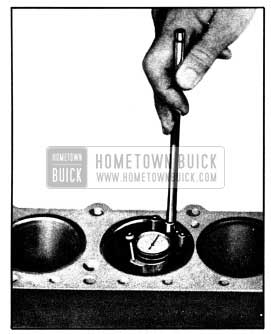
1950 Buick Checking Cylinder Bore with Gauge
The diameter of cylinder bore at any point may be measured with an inside micrometer, or by setting the cylinder gauge dial at “0” and measuring across the gauge contact points with outside micrometer while gauge is at the same “0” setting.
If a cylinder bore is moderately rough or slightly scored but is not out-of-round or tapered, it usually is possible to remedy the condition by honing the bore to fit a standard service piston, since standard service pistons are of high limit diameters. If cylinder bore is very rough or deeply scored, however, it may be necessary to rebore the cylinder and fit an oversize piston in order to insure satisfactory results.
If cylinder bore is tapered .005″ or more, or is out-of-round .003″ or more, it is advisable to rebore for the smallest possible oversize pistons and rings. With this amount of bore wear, some piston wear has usually taken place so that the total clearance in the ring travel will be sufficient to produce noisy piston operation.
Inspection of Pistons, Rings and Pins
Clean carbon from piston surfaces and underside of piston heads. Clean carbon from ring grooves with suitable tool and clean out oil holes in oil ring grooves. Remove any gum or varnish from piston skirts with suitable solvent.
Carefully examine pistons for rough or scored bearing surfaces, cracks in skirt or head, cracked or broken ring lands, chipping or uneven wear which would cause rings to seat improperly or have excessive clearance in ring grooves. Damaged or faulty pistons should be replaced.
The pistons are cam ground, which means that the diameter at right angle to piston pin is greater than the diameter parallel to piston pin. When a piston is checked for size it must be measured with a micrometer applied to skirt at points exactly 90 degrees to piston pin. See figure 2-29.
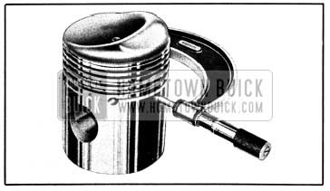
1950 Buick Measuring Piston with Micrometer
Measurements should be made at top and bottom ends of skirt; the diameter at top end will normally be very slightly less than at bottom end after a piston has been in service in an engine.
Inspect bearing surfaces of piston pins and check for wear by measuring worn and unworn surfaces with micrometers. Rough or worn pins should be replaced. Test fit of piston pins in
piston bosses. Sometimes pins will be found tight due to gum or varnish deposits. This may be corrected by removing the deposit with a suitable solvent.
If piston bosses are worn out-of-round or oversize and the piston is otherwise satisfactory for service, the bosses and connecting rods may be honed or reamed for oversize piston pins which are furnished for service. Piston pins must fit pistons with an easy finger push fit at 70°F.
Examine all piston rings for scores, chips, or cracks, and for tension as compared with new rings. Place all rings except Flex-Fit rings in cylinder bores at lower end of ring travel and check gaps, which are normally .010″ to .020″. If gaps are excessive it indicates that rings have worn considerably and should be replaced.
Reboring Cylinders and Fitting New Pistons
If one or more cylinder bores are rough, scored, or worn beyond limits prescribed under Inspection of Cylinder Bores (subpar. b), it will be necessary to smooth or true up such bores to fit new pistons.
If relatively few bores require correction it will not be necessary to rebore all cylinders to the same oversize in order to maintain engine balance, since all over-size service pistons are held to the same weights as standard size pistons. If conditions justify replacement of all pistons, however, all new pistons should be the same nominal size.
Standard size service pistons are high limit or maximum diameter; therefore, they can usually be used with a slight amount of honing to correct slight scoring or excessive clearances in engines having relatively low mileage. Service pistons are also furnished in .005″, .010″, .020″ and .030″ oversizes. All service pistons are diamond bored and selectively fitted with piston pins; pistons are not furnished without pins.
No attempt should be made to cut down oversize pistons to fit cylinder bores as this will destroy the surface treatment and affect the weight.. The smallest possible oversize service pistons should be used and the cylinder bores should be honed to size for proper clearances.
Before the honing or reboring operation is started, measure all new pistons with micrometer contacting at points exactly 90 degrees to piston pin (fig. 2-29) then select the smallest piston for the first fitting. The slight variation usually found between pistons in a set may provide for correction in case the first piston is fitted too free.
If a rebore job is required, a boring bar of the fly cutter type is recommended. When reboring the cylinders, all crankshaft bearing caps must be in place and tightened to proper torque to avoid distortion of bores in final assembly. After reboring it is always advisable to polish cylinder bores with crocus cloth, to eliminate excessive wear on pistons and rings.
If cylinder bores are to be honed, use clean sharp stones of proper grade for the amount of metal to be removed. Dull or dirty stones cut unevenly and generate excessive heat. When using coarse or medium grade stones use care to leave sufficient metal so that all stone marks may be removed with the fine stones used for finishing. The final honing must be done with the finest grade of stones and the cylinder walls must be polished with crocus cloth to produce a very smooth finish.
It is of the greatest importance that refinished cylinder bores are trued up to have not over .0005″ out-of-round or taper. Each bore must be final honed to remove all stone or cutter marks and provide a smooth surface. During final honing, each piston must be fitted individually to the bore in which it will be installed and should be marked to insure correct installation.
After final honing and before the piston is checked for fit, each cylinder bore must be thoroughly washed to remove all traces of abrasive and then dried thoroughly. The dry bore should then be brushed clean with a power driven fibre brush. If all traces of abrasive are not removed, rapid wear of new pistons and rings will result.
Both the piston and the cylinder block must be at the same temperature of approximately 70° F. when the piston is checked for fit in cylinder bore; therefore the cylinder should be allowed to cool after boring or honing and before the piston fit is checked. This is important because a difference of 10° F. between parts is sufficient to produce a variation of .0005″.
The high and low limits on clearance of pistons in cylinders at 70° F. are given in the following table. The clearance should be measured with two feeler gauges of “Go” and “No Go” thicknesses specified in the table:
Feeler gauges should be approximately 12″ long and 1/2″ wide, except that the “Go” gauge should be 1/4″ wide, if obtainable, since this width gives a more sensitive test of clearance. Feeler gauges must be free of dents, burrs and rough edges.
Wipe pistons and cylinder walls clean and dry, then wet pistons and cylinders with penetrating oil, which will materially aid in determining fits with feeler gauges.
Suspend the specified “Go” feeler gauge full length in cylinder bore at point 90 degrees to centerline of engine, then insert piston into bore with head downward and piston pin parallel to centerline of engine. See figure 2-30.
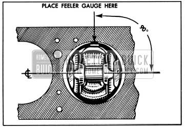
1950 Buick Position of Feeler Gauge for Checking Fit of Piston
The piston should move downward the length of cylinder by its own weight when tested with the “Go” feeler gauge. Repeat the test using the specified “No Go” feeler gauge; the piston should fit closely enough so that it will not move downward by its own weight.
Occasionally an engine which has been rebored will continue to use oil excessively after sufficient mileage has accumulated to break in new rings. This indicates that cylinder bores were not finished as smoothly as required. The rings will polish the cylinder wall but will be worn excessively in doing so. Installation of a new set of rings will frequently correct such cases; however, the cylinder bores should not be honed to remove glaze when the second set of rings is installed.
Fitting New Piston Rings
When new piston rings are installed without reboring cylinders, the glazed cylinder walls should be slightly dulled, but without increasing the bore diameter, by means of the finest grade of stones in a cylinder hone.
New piston rings must be checked for clearance in piston grooves and for gap in cylinder . bores; however, the Flex-Fit rings are not checked for gap. The cylinder bores and piston grooves must be clean, dry and free of carbon and burrs.
Check the clearance of each ring in its piston groove by installing the ring and then inserting feeler gauges under the ring. Any wear that occurs in the piston groove forms a step or ridge at inner portion of the lower land. If gauges are inserted above the ring, the ring may rest on the step instead of on the worn portion of the lower land, and a false measurement of clearance will result.
If the piston grooves have worn to the extent that relatively high steps or ridges exist on the lower lands, the piston should be replaced because the steps will interfere with the operation of new rings and the ring clearances will be excessive. Piston rings are not furnished in oversize widths to compensate for ring groove wear.
Piston rings should have not less than .0015″ nor more than .004″ clearance in piston grooves.
To check the gap of rings other than FlexFit, place the ring in the cylinder in which it will be used, square it in the bore by tapping with the lower end of a piston, then measure the gap with feeler gauges. Piston rings should not have less than .010″ gap when placed in cylinder bores. If gap is less than .010″, file the ends of rings carefully with a smooth file to obtain proper gap.
Assembly and Installation of Piston and Connecting Rod Assemblies
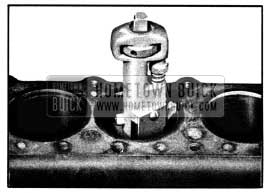
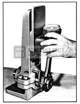
- Connecting rods may be sprung out of alignment in shipping or handling, therefore, they must always be checked before pistons are installed. Clamp a new piston pin in upper end of connecting rod and test the rod for twist and bend, using an accurate connecting rod aligning fixture. See figure 2-31. Bend or twist the rod if necessary, to secure proper alignment.
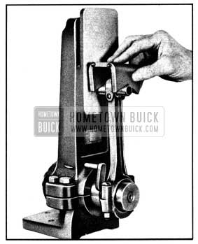
1950 Buick Checking Connecting Rod Alignment
- Install the piston and pin on connecting rod with the hollow side of piston head on same side as the small oil hole in rod. Tighten the piston pin clamp bolt securely. Do not clamp the rod in a vise for this operation as the rod may be sprung out of alignment when tightening clamp bolt, or if vise jaws are not square.
- Check alignment of rod and piston in the connecting rod aligning fixture. See figure 2-32.
1950 Buick Checking Connecting Rod and Piston Alignment
- Install channeled oil ring in third groove and compression rings in second and first grooves of each piston. Be sure to place the grooved or beveled side of compression rings toward top of piston. To avoid distortion or breakage of rings use Ring Remover and Installer KMO 297-D (Series 40) , KMO 297-G (Series 50) or KMO 297-E (Series 70). See figure 2-27.
- Make sure that cylinder bores, pistons, connecting rod bearings and crankshaft journals are absolutely clean, then coat all bearing surfaces with engine oil.
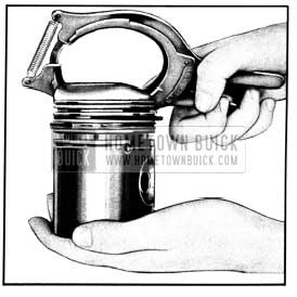
- Before installation of each piston and rod assembly in cylinder bore, carefully place the Flex-Fit oil ring in the bottom groove and compress it with a tapered sleeve ring compressor of proper size. Make sure that inner surface of compressor is clean, smooth and free of burrs. The compressor must be pulled toward top of piston to compress the Flex-Fit ring as well as the other piston rings. See figure 2-33.
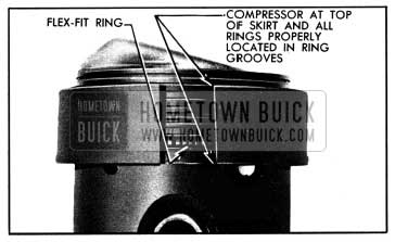
1950 Buick Rings Held in Place by Compressor
NOTE : Turn each ring so that gap is not in line with gap of any other ring. Always locate the open end of compressor diametrically opposite the open end of Flex-Fit ring. If ring and compressor openings coincide, the ring ends will squeeze out and hang up on cylinder bore.
- Insert rod and piston assembly into cylinder bore with hollow side of piston toward camshaft. With ring compressor resting squarely on top of cylinder crankcase, snap the piston down into bore by using the thumbs as shown in figure 2-34.
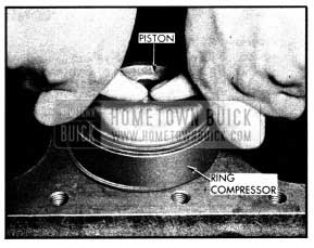
1950 Buick Snapping Piston Into Cylinder Bore
An alternate method is to grip the compressor firmly as if to close the gap, then lightly tap the piston down with a hammer handle. If the piston does not enter cylinder bore without excessive force, remove the assembly and check for the cause.
- Select connecting rod bearings as described in paragraph 2-21.
- Install cylinder head (par. 2-16), oil pump (par. 2-30) and lower crankcase.
- When connecting steering tie rod to pitman arm, be careful to properly seat the bearings around the ball stud and make sure that the pressed steel dust cover properly covers opening around ball stud. Turn tie rod plug up solid then back off two turns and install cotter pin.
IMPORTANT: After installation of new pistons and rings, care should be used in starting the engine and in running it for the first hour. Avoid high speeds until the parts have had a reasonable amount of break-in so that scuffing will not occur.
Leave A Comment
You must be logged in to post a comment.