SECTION 8-D 1950 BUICK BRAKE REPLACEMENT AND REPAIR PROCEDURES
8-16 REPLACE OR RELINE BRAKE SHOES
The most satisfactory method of replacing brake lining is to install new shoe and lining assemblies. This insures brake shoes that are not distorted through use, and linings properly riveted to shoes and ground to correct radius by accurate factory machinery.
Each brake shoe and lining set listed under Group 5.017 contains two primary and two secondary shoe and lining assemblies, enough for two wheels. Sets are available in standard size and also in .030″ oversize for use where brake drums have been rebored.
Use brake shoe lining sets listed under Group 5.018 if the old brake shoes are to be relined. Each lining set contains two primary and two secondary linings, enough for two wheels. Linings are shaped, drilled, and ground to correct thickness and radius, and are packaged with enough rivets for installation on shoes. Linings sets are available in standard and .030″ oversizes.
Two optional types of primary and secondary brake shoe lining material are approved for production and service. Because these materials have slightly different braking characteristics, primary and secondary linings must be of same type in each brake assembly. These different types cannot be distinguished by inspection; however, a carton of linings or shoes contains only one type of material.
To insure equal braking action it is essential that left and right brake assemblies at either end of car contain the same type of lining material. It is not necessary, however, that front and rear brake assemblies contain the same type of material. When replacing linings or shoes install contents of one carton on left and right sides at same end of car-do not install contents of one carton in front and rear brake assemblies.
The following procedure covers 1950 Buick brake replacement of shoe and lining assemblies and also relining of old shoes at any one wheel. Additional operations are specified where inspection may indicate their need. Each additional operation is identified by an asterisk ( *) preceding the reference to paragraph number covering the operation.
Removal and Inspection
- Jack up car in a safe manner, remove wheel, then remove brake drum (rear) or drum and hub assembly (front). NOTE: Since stops are located on brake backing plate to prevent pistons from leaving wheel cylinder, it is not necessary to install wheel cylinder clamps when drums are removed; however, brake pedal must not be operated while drum is removed.
- Unhook shoe return springs from anchor pin, using large pliers and being careful not to nick or distort springs. Remove shoe hold down springs, spread shoes to clear wheel cylinder connecting links, remove parking brake strut (rear only), and remove shoes from backing plate. Disconnect cable from parking brake lever (rear only). See figure 8-11.
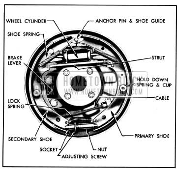
1950 Buick Rear Wheel Brake Assembly-Right
- Separate the brake shoes by removing adjusting screw and lock spring. Remove parking brake lever from secondary brake shoe (rear lever (rear only). See figure 8-11.
- Clean all dirt out of brake drum, using care to avoid getting dirt into front wheel bearings. Inspect drums and replace or recondition if required (*par. 8-17). If front drum and hub is removed, inspect wheel bearings and oil seal packings and replace faulty parts (*par. 6-14).
- Carefully pull lower edges of wheel cylinder boots away from cylinders and note whether interior is wet with brake fluid. Fluid at this point indicates leakage past piston cup, requiring overhaul of wheel cylinder (*par. 8-18).
- If working at rear wheels, inspect backing plate for oil leak past wheel bearing oil seals. Correct any leak by installation of new seals (*par. 5-9).
- Check all backing plate attaching bolts to make sure they are tight. Clean all rust and dirt from shoe contact surfaces on plate, using fine emery cloth.
Relining Brake Shoes
If old brake shoes are to be relined, inspect shoes for distortion and for looseness between the rim and web; these are causes for discarding any shoe. If shoes are serviceable, be governed by the following points in installing new linings:
- Remove old linings by drilling out rivets. Punching rivets out will distort shoe rim. Thoroughly clean surface of shoe rim and file off any burrs or high spots.
- Use only genuine Buick brake lining and the rivets included in lining package which are of correct size. The rivets must fit the holes and the solid body of rivet should extend through the shoe rim, but no farther.
- Keep hands clean while handling brake lining. Do not permit oil or grease to come in contact with lining.
- Start the riveting at center of shoe and lining and work toward the ends. Use a roll set for riveting; a star set might split the tubular end and then the rivet would not fill the hole. The primary lining is shorter than secondary lining, therefore the rivet holes at each end of shoe rim are not used.
- After riveting is completed, lining must seat snugly against shoe with no more than .005″ separation midway between rivets. Check with a .004″ (permissable) and a .006″ (no go) feeler gauge.
- It is not necessary to grind Buick linings after installation on shoes as linings are correctly ground in production. It is advisable, however, to place shoes in drum and check for proper arc and fit in drum, using feeler gauges. No more than .004″ clearance should exist between lining and drum at any point.
Installation and Adjustment
- If working on rear brakes, lubricate parking brake cable (par. 8-14).
- On rear brakes only, lubricate fulcrum end of parking brake lever and the bolt with Bendix or Delco Brake Lubricant, or Lubriplate, then attach lever to secondary shoe with bolt, spring washer, nut, and Pal nut. Make sure that lever is free moving. See figure 8-11.
- Connect brake shoes together with lock spring, then place adjusting screw, socket, and nut in position. The socket and star wheel must be adjacent to primary shoe on front brake, and adjacent to secondary shoe on rear brake.
- Attach brake shoes to backing plate with hold down springs, pins, and cups, at the same time engaging shoes with wheel cylinder connecting links. The primary shoe (short lining) goes forward. On rear brakes, connect cable to parking brake lever and install strut between lever and primary shoe as installation is made. See figure 8-11.
- If old brake shoe return springs are nicked, distorted, or if doubtful strength it is advisable to install new ones. Hook springs in shoes and over end of anchor pin, using large pliers and being careful not to nick or distort springs.
- Pry shoes away from backing plate and lubricate shoe contact surfaces with a thin coating of Bendix or Delco Brake Lubricant, or Lubriplate. On rear brakes, sparingly apply same lubricant where brake cable contacts backing plate.
- Install brake drum and wheel. If working on front brake lubricate and adjust front wheel bearings (par. 6-14). Remove adjusting hole cover from backing plate.
- Centralize brake shoes and set anchor pin, then adjust all brake shoes and brake cable as described in paragraph 8-15, steps 17 through 22.
IMPORTANT: Brakes must not be severely applied immediately after installation of new brake shoes or linings. Severe application may permanently injure new linings and may score brake drums. When linings are new they must be given moderate use for several days until nicely burnished.
8-17 INSPECTING AND RECONDITIONING 1950 BUICK BRAKE DRUMS
Whenever brake drums are removed they should be thoroughly cleaned and inspected for cracks, scores, deep grooves, and out-of-round. Any of these conditions must be corrected since they can impair the efficiency of brake operation and also can cause premature failure of other parts.
Cracked Drum
A cracked drum is unsafe for further service and must be replaced. Welding a cracked drum is not recommended.
Scored Drum
Smooth up any slight scores by polishing with fine emery cloth. Heavy or extensive scoring will cause excessive brake lining wear and it will probably be necessary to rebore in order to true up the braking surface.
Grooved Drum
If the brake linings are little worn and drum is grooved, the drum should be rebored just enough to remove grooves and the ridges in the lining should be lightly removed with a lining grinder.
If brake linings are more than half worn, but do not need replacement, the drum should be polished with fine emery cloth but should not be rebored. At this stage, eliminating the grooves in drum and smoothing the ridges on lining would necessitate removal of too much metal and lining, while if left alone, the grooves and ridges match and satisfactory service can be obtained.
If brake linings are to be replaced, a grooved drum should be rebored for use with oversize linings (subpar. e, below). A grooved drum, if used with new lining, will not only wear the lining but will make it difficult, if not impossible, to obtain efficient brake performance.
Out-of-Round Drum
An out-of-round drum makes accurate brake shoe adjustment impossible and is likely to cause excessive wear of other parts of brake mechanism due to its eccentric action. An out of-round drum can also cause severe and very irregular tire tread wear.
A drum that is more than .010″ out-of-round on the diameter is unfit for service and should be rebored (subpar. e, below). Out-of-round as well as taper and wear can be accurately measured with an inside micrometer fitted with proper extension rods.
When measuring a drum for out-of-round, taper, and wear, take measurements at the open and closed edges of machined surface and at right angles to each other. Figure 8-12 gives the machining specifications for a standard brake drum, which will aid in determining the condition of drum being inspected.
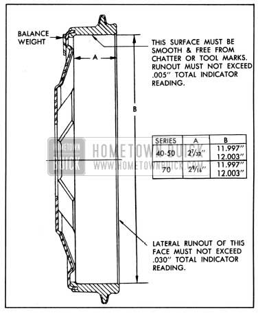
1950 Buick Machining Specifications for Standard Brake Drum
Reboring Brake Drum
If drum is to be rebored for use with standard size brake linings which are worn very little, only enough metal should be removed to obtain a true, smooth braking surface as specified in figure 8-12. If drum has to be rebored more than .010″ over the standard diameter, however, it should be rebored to .030″ oversize and the brake lining should be replaced with .030″ oversize lining.
A brake drum must not be rebored more than .060″ over the standard diameter given in figure 8-12, since removal of more metal will affect dissipation of heat and may cause distortion of drum. Buick brake lining is not furnished larger than .030″ oversize and this will not work efficiently in drums bored more than .060″ oversize.
Brake drums may be refinished either by turning or grinding. Best brake performance is obtained by turning drums with a very fine feed. Ground and polished drums do not wear in as readily as turned drums and are more likely to cause unequal braking when new. To insure maximum lining life, the refinished braking surface must be smooth and free from chatter or tool marks, and run-out must not exceed .005″ total indicator reading. See figure 8-12.
Brake Drum Balance
Brake drums must not be out of balance more than 6 inch ounces. During manufacture, drums are balanced within this limit by welding weights, as required, to the flange near the rim. These weights must never be removed. See figure 8-12.
After drums are rebored, or if difficulty is experienced in maintaining proper wheel balance, it is recommended that brake drums be checked for static balance. Drums out of balance more than 6 inch ounces may be corrected by installation of service balance weights as shown in figure 8-13.
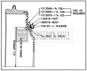
1950 Buick Brake Drum Balance Weights-Service Application
These balance weights are furnished in three sizes under Group 5.810. Brake drums may be checked for balance on any machine suitable for balancing wheels.
8-18 1950 BUICK BRAKE WHEEL CYLINDER OVERHAUL
- Remove wheel, drum, and brake shoes. Be careful not to get grease or dirt on brake linings.
- Disconnect brake pipe or hose from wheel cylinder and cover opening with tape to prevent entrance of dirt. Remove wheel cylinder from backing plate.
- Remove links, boots, and piston cups and spring from cylinder. Remove bleeder valve. See figure 8-3.
- Discard rubber boots and piston cups. Thoroughly clean all other parts with Declene Flushing Fluid, hydraulic brake fluid or a good grade of alcohol. CAUTION: Do not use gasoline, kerosene, O?’ any other cleaning fluid that might contain even a trace of mineral oil.
- Inspect pistons and cylinder bore for scores, deep scratches, or corrosion. Light scratches and slightly corroded spots in cylinder bore may be polished with crocus cloth. Do not use emery cloth or sand paper. If scratches or corroded spots are too deep to be polished satisfactorily with crocus cloth the cylinder should be replaced since honing is not recommended and oversize pistons and cups are not furnished for service.
- Dip internal parts in brake fluid and reassemble wheel cylinder. When installing piston cups use care to avoid damaging the edges. NOTE: Front wheel cylinder pistons and cups are 1 1/8″ diameter and rear wheel cylinder parts are 1″ diameter.
- Install wheel cylinder on brake backing plate and connect brake pipe or hose.
- Install brake shoes, drum, and wheel, then flush and bleed hydraulic system (par. 8-10).
- Adjust brakes (par. 8-12) then road test car for brake performance (par. 8-5 and 8-6).
8-19 1950 BUICK BRAKE MASTER CYLINDER OVERHAUL
- Jack up both ends of car in a safe manner.
- Disconnect master cylinder inner and outer push rods at pedal adjusting nut (fig. 8-7). Disconnect brake pipe from master cylinder and tape end of pipe to prevent entrance of dirt. Remove master cylinder from frame side rail.
- Remove filler cap nut and drain all fluid from master cylinder. Remove head nut, check valve, and spring. Turn the boot back, remove lock ring, then remove push rod, stop plate, piston, and primary cup. See figure 8-14.
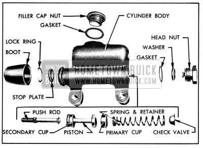
1950 Buick Master Cylinder-Disassembled
- Discard head nut gasket and washer, check valve, spring and retainer, piston and rubber cups, lock ring, and boot. These parts are furnished in the master cylinder repair kit, (Group 4.649).
- Thoroughly clean all other parts with Declene Flushing Fluid, hydraulic brake fluid, or a good grade of alcohol. CAUTION: Do not use gasoline, kerosene, or any other cleaning fluid that might contain even a trace of mineral oil.
- Inspect cylinder barrel for scores, deep scratches, or corrosion. Light scratches and slightly corroded spots in cylinder barrel may be polished with crocus cloth. Do not use emery cloth or sandpaper. If scratches or corroded spots are too deep to be polished satisfactorily with crocus cloth the cylinder should be replaced since honing is not recommended and oversize pistons and cups are not furnished for service.
- Make certain that compensating port in cylinder is clear; however, do not run a wire through port as this may result in leaving a burr which will cut a groove in primary cup.
- Install stop plate, lock ring, push rod and boot. Dip internal parts in brake fluid, then install piston with secondary cup, primary cup, spring with retainer against primary cup, check valve, and head nut with rubber washer and gasket. Tighten head nut securely. Install filler cap nut and gasket to keep dirt out of reservoir. See figure 8-14.
- Install master cylinder on frame side rail. Connect brake pipe. Connect master cylinder push rods and adjust brake pedal for proper clearance (par. 8-11).
- Flush and bleed hydraulic system (par. 8-10).
- Remove car jacks and road test car for brake performance (par. 8-5 and 8-6).
Looking on how the spring go,on the front brake thank u