SECTION 10-H 1952 BUICK SIGNAL SYSTEMS
10-58 1952 BUICK STOP LIGHTS AND SWITCH
The 1952 Buick stop lights are incorporated in the combination tail, stop, and direction signal lamps. These lamps and the replacement of bulbs are covered in paragraph 10-56.
The 1952 Buick stop lights are controlled by a hydraulic switch mounted on the brake pipe distributor fitting near the master cylinder. The switch is closed by hydraulic pressure when the brakes are applied. It requires no adjustment or attention except to make sure that the wire connections are tight and that the switch is tightly screwed into the distributor fitting to avoid fluid leaks that would affect operation of the brakes.
The stop lights are independent of the lighting switch. The stop light circuit is protected by the 14 ampere “Direction Signal” fuse mounted on the 1952 Buick fuse block under the cowl.
Replacement of 1952 Buick Stop Light Switch
When replacing 1952 Buick stop light switch have new switch ready to install as soon as old switch is removed from distributor fitting. Before installing new switch make sure that port in distributor fitting is filled with brake fluid. Have a helper gently depress brake pedal to fill the fitting from master cylinder, if necessary, then immediately install new switch.
If 1952 Buick brake pedal has springy, spongy action after installation of stop light switch, air has entered brake pipes and it will be necessary to bleed the hydraulic system (par. 8-9).
10-59 1952 BUICK HORNS, RELAY AND BUTTON
1952 Buick Horns and Relay
Two Delco-Remy electrically operated vibrator type horns are mounted on the radiator mounting strap. Both 1952 Buick horns are operated simultaneously by a horn relay mounted on radiator mounting strap; the relay is controlled by the horn button on steering wheel.
The left hand horn is high pitched (380-400 cycles) and the right hand horn is low pitched (302-323 cycles), so that together they produce a pleasing blended tone. The horns have been made exceptionally compact by a spiral air column cast into the base and collar. See figure 10-95.
1952 Buick Horn Contact Point Adjustment
The 1952 Buick horn relay is an electrical switch which closes the circuit between the battery and the horns when the horn button is pressed, and opens the circuit when the button is released. The relay permits control of the horns with a small amount of current passing through the horn button contacts. The high current required by the horns would cause arcing and burning of these contacts.
When the 1952 Buick horn button contacts are closed, a small amount of current flows through the relay winding to ground at the horn button. This magnetizes the relay core, which attracts the flat steel relay armature. The armature has a contact point which makes contact with a stationary point to close the horn circuit. When horn button is released, current stops flowing through relay winding so that the core loses its magnetism; the armature spring then causes contact points to be separated.
1952 Buick Horn Button – Flexible Spoke Steering Wheel
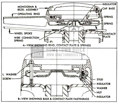
The 1952 Buick horn button used with the 1952 Buick flexible spoke steering wheel includes an operating ring and a contact plate mounted in the steering wheel cap base. A spring holds the wire connection against the center of the contact plate which is insulated from the wheel cap base. When the operating ring is pressed it touches the contact plate to close the circuit to ground, thus completing the relay circuit and causing the horns to operate. Springs cause the operating ring to move away from the contact plate and open the relay circuit when the operating ring is released. See figure 10-93.
1952 Buick Horn Button In Flexible Spoke Steering Wheel- Sectional View
The monogram and bezel assembly is held in the steering wheel cap base by three springs.
The assembly may be removed by inserting a small screw driver in a notch provided in the cap base and prying against the bezel. When the monogram and bezel assembly are removed, the operating ring and wheel base assembly may be removed by removing the three screws which attach the wheel base to the steering wheel hub. See figure 10-93.
1952 Buick Horn Button-Solid Spoke Steering Wheel
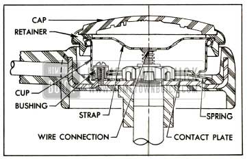
The 1952 Buick horn button assembly used in the solid spoke steering wheel consists of a horn button cap with contact strap, a contact cup, a horn blowing spring, a contact plate, and attaching screws with insulating fibre spacer bushings.
The 1952 Buick horn button cap has a rubber retainer which snaps over the rim of the contact cup and the contact strap bridges between the horn wire connector in steering shaft and the rim of contact cup. The contact cup is attached to steering wheel hub by three screws and insulating fibre spacer bushings which permit movement of the cup when button cap is pressed. The screws and bushings hold the flat steel contact plate tight against the wheel hub. The dished steel horn blowing spring is placed between the cup and contact plate, with outer rim of spring resting on a shoulder of the plastic material of wheel, which provides insulation. See figure 10-94.
1952 Buick Horn Button Parts In Solid Spoke Steering Wheel
Normally, the dished spring holds the contact cup outward so that no contact is made, but when the cap is pressed the cup pushes the raised inner edge of the spring down into contact with the plate, thereby completing a grounding connection between the horn wire connector and the steering shaft.
Whenever 1952 Buick horn button parts are assembled into the steering wheel the dished horn blowing spring must be installed so that clearance exists between inner edge of spring and the contact plate. See figure 10-94. The contact cup must be installed with the locating notch in rim in line with lower spoke of steering wheel so that the 1952 Buick horn button cap emblem will be properly located when cap is installed.
10-60 ADJUSTMENT OF 1952 BUICK HORNS
When 1952 Buick horns fail to blow first check wiring circuit (par. 10-12, c) before attempting to adjust horns. If 1952 Buick horns are at fault, or tone is poor, adjust each horn for specified current draw as follows:
- Remove 1952 Buick horn from car and remove the back shell, which is crimped over the collar at four points.
- Inspect air gap between armature and core for steel burrs or other foreign matter; clean out if present. This may correct the trouble. If it does not, proceed as follows:
- Connect an ammeter in series with the horn and a fully charged 6-volt battery to measure the current draw when horn blows. Current draw should be as follows:
- Left (high note) horn 16 to 18 amperes
- Right (low note) horn 17 to 19 amperes
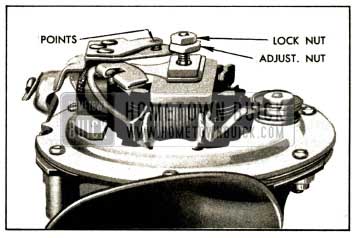
- Adjust to specified current draw, if necessary, by loosening lock nut and turning contact point adjusting nut clockwise to decrease or counterclockwise to increase current draw. See figure 10-95. This adjustment is very sensitive, and adjusting nut should not be moved more than one-tenth turn at a time, then locked with nut each time before trying the horn.
Increasing the current draw increases the horn volume. Too much current will produce a high cut-in voltage, which will cause a sputtering sound and may cause horn to stick in cold weather.
- After each horn has been adjusted individually, sound both horns together to check for proper blend of tone.
- After horn adjustment is completed install the back shell. Make sure that back shell is seated against horn collar all around, then crimp tangs of shell over collar at four points.
- When horns are reinstalled, connect a voltmeter between each horn terminal and ground to check voltage when horns are blown. Voltage at each horn should be at least 5.25.
10-61 ADJUSTMENT OF 1952 BUICK HORN RELAY
Three checks and adjustments are required on the 1952 Buick horn relay: air gap, point opening, and closing voltage. These should be made in the following order:
- Remove 1952 Buick horn relay from car then remove relay cover.
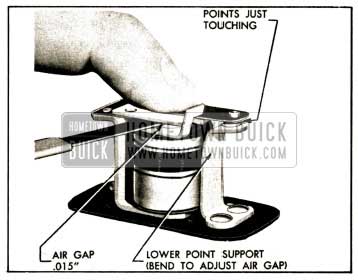
- Push relay armature down until contact points just touch, then check air gap between armature and end of core using feeler gauges. Air gap should be .015″. Adjust gap to .015″, if necessary, by bending the lower point support. See figure 10-96.
1952 Buick Horn Relay Air Gap Adjustment
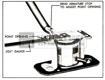
1952 Buick Horn Relay Contact Point Adjustment
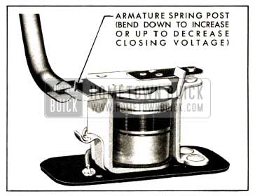
1952 Buick Adjustment of Horn Relay Closing Voltage
10-62 1952 BUICK DIRECTION SIGNAL LAMPS AND SWITCH
1952 Buick Direction Signal Lamps and Indicators
The 1952 Buick directional signal lamps are incorporated in the front parking lamps and the rear combination tail, stop and signal lamps.
Each front parking lamp contains a 21-3 CP lamp bulb; the 3 CP bulb filament is used for parking and the 21 CP bulb filament is used for the directional signal light. Each rear lamp contains a separate 21 CP lamp bulb for the direction signal light, which operates independently of the tail and stop lights.
When the 1952 Buick ignition switch is turned on and the direction signal switch is manually operated to indicate a turn, the front and rear signal lights flash on and off on the side of car for which a turn is indicated. The flashing of 1952 Buick signal lights is caused by a Tungsol flasher which is connected into the proper signal light circuit by contacts made in the direction signal switch when switch is set for a turn.
When the 1952 Buick direction signal lights are flashing, a signal indicator bulb on instrument panel also flashes, producing a small arrow of green light to indicate the direction for which the signal has been set.
1952 Buick Direction Signal Switch Operation
The 1952 Buick direction signal switch and its operating mechanism are enclosed in a switch housing on the steering column just below steering wheel.
The switch is operated by a lever projecting from the left side of switch housing. Moving the operating lever clockwise sets the switch to indicate a right turn and moving lever counterclockwise indicates a left turn.
The operating lever is locked by a set screw into a stub shaft anchored to a plate in switch housing which operates the switch. The stub shaft fits into a recess in the housing to provide a bearing or pivot point for the lever and plate. A slot in right side of the lever plate engages the bakelite handle of the switch which is mounted in the housing below the lever plate. A detent spring mounted in the housing bears against a roller mounted on the lever plate to hold the plate in whatever position it may be set. Bosses in the housing provide stops- for the plate when set for either turn. See figure 10-99.
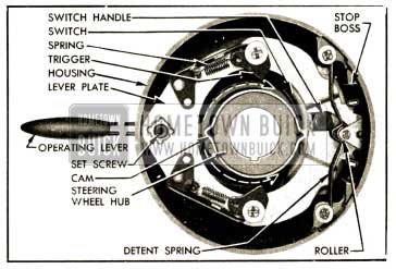
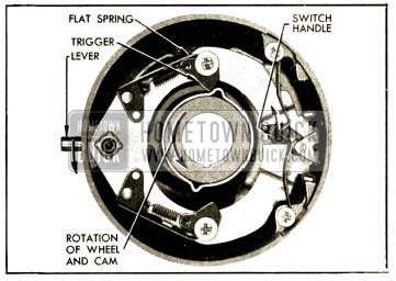
1952 Buick Direction Signal Switch in Off Position
The trip mechanism for returning the switch to the “off” position after a turn is completed consists of a cam on the steering wheel hub, and two spring loaded triggers mounted on the lever plate. The cam is a round steel stamping having two projecting ribs, and it is rigidly mounted on the wheel hub. When the switch is in the “off” position, the lever plate is centered around the cam so that the ribs of cam cannot contact either trigger when steering wheel is turned. See figure 10-99.
When the operating lever is moved clockwise to set the switch for a right turn the lever plate is moved down, thereby moving the switch handle down and also bringing the upper trigger into the path of the cam ribs. As the steering wheel is turned right and a cam rib contacts the trigger, the trigger rotates to permit the cam rib to pass without interference. The coil spring then returns the trigger to its original position. See figure 10-100.
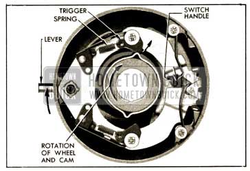
1952 Buick Direction Signal Switch Set for Right Tum
As the steering wheel is turned left at completion of the right turn the cam rib again contacts the trigger, which is prevented from rotating out of the way by a flat spring mounted on the lever plate. The cam rib pushes against the trigger to move the lever plate and switch back to the “off” position. See figure 10-101.
1952 Buick Direction Signal Switch Release Following A Right Turn
The flat spring cushions the shock as the cam rib contacts the trigger, and it would also permit the trigger to rotate out of the way and let the steering wheel turn in case anything held the lever and plate from returning to “off” position.
The same action takes place when the switch is set for a left turn, except that the lever plate is moved up to bring the lower trigger into contact with the cam. If the switch is erroneously set to indicate a turn in one direction and the turn is made in the opposite direction, the opposite rib of cam will contact the trigger and return the switch to “off” position as the wrong turn is started.
Replacement of 1952 Buick Signal Switch Parts
- Remove 1952 Buick steering wheel (par. 7-5).
- Use a 1/8″ hex (Allen) wrench to loosen the operating lever set screw and remove lever. See figure 10-99. NOTE: If only the lever requires replacement remove horn button only, then insert wrench through a puller hole in steering wheel to loosen the set screw.
- Remove lever plate detent spring, then lift the lever plate out of switch housing.
- If switch is to be replaced, disconnect signal switch wires from fuse block under the cowl, remove switch attaching screws, then carefully pull the switch and wiring harness assembly out through switch housing.
- When switch and wiring harness assembly is installed, connect switch wires to fuse block as shown in the chassis wiring circuit diagrams in Section 10-J.
- Before installing the lever plate, apply a light coat of Lubriplate to the top of 1952 Buick signal switch and to the stub shaft on lever plate.
- Install steering wheel as described in paragraph 7-5.
1952 Buick Direction Signal Lamp Circuits
Since the 1952 Buick direction signal lights are independent of the headlamp lighting switch and thermo circuit breaker, the wiring circuits are protected by a “Direction Signal” fuse on the fuse block under the cowl. The Tungsol flasher is also mounted on the fuse block, which serves as a terminal block between the 1952 Buick signal switch and the chassis wiring.
The 1952 Buick direction signal lights are independent of the parking and stop light circuits, and the indicator lamp bulb sockets are grounded to the instrument panel.
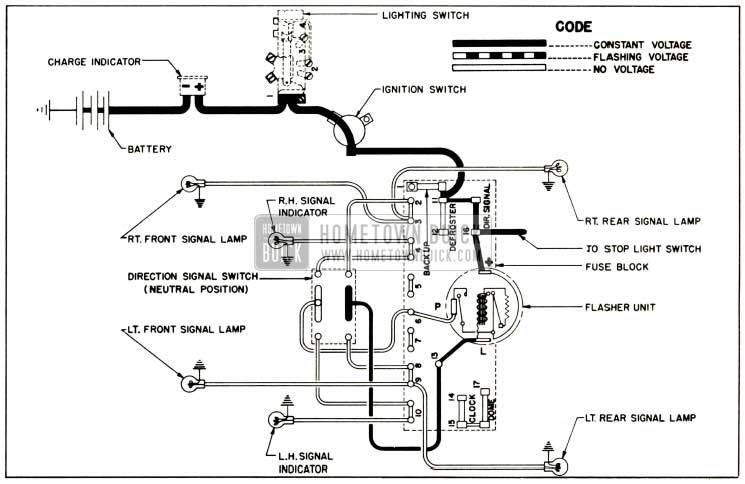
1952 Buick Direction Signal Lamp Circuit Diagram, No Turn Indicated
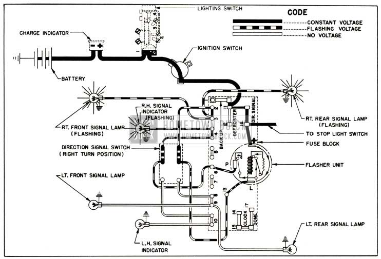
1952 Buick Direction Signal Lamp Circuit Diagram, Right Turn Indicated
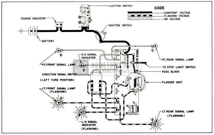
1952 Buick Direction Signal Lamp Circuit Diagram, Left Turn Indicated
Figures 10-102, 10-103 and 10-104 show the direction signal circuits when signal switch is set for No Turn, Right Turn, and Left Turn. 1952 Buick direction signal switch wiring is also shown in the chassis wiring circuit diagrams in Section 10-J.
Leave A Comment
You must be logged in to post a comment.