SECTION 13-C 1952 BUICK WINDSHIELD WIPERS, WINDSHIELD,
13-10 1952 BUICK WINDSHIELD WIPERS
Description of Windshield Wipers
The 1952 Buick Series 40 windshield wiper motor is mounted under the cowl and is connected to the right and left windshield wiper transmission by steel links which are part of the transmission assemblies. Rubber inertia arresters are built into the drive lever on the motor and the driven levers on the transmissions for the purpose of absorbing the shock produced by reversal of direction at the end of each stroke.
The 1952 Buick Series 50 and 70 windshield wiper motor is mounted on an auxiliary drive which is attached to the front face of the cowl panel, under the hood. The motor drives a short shaft in the auxiliary drive which extends through the cowl panel. A cross lever on rear end of the auxiliary shaft actuates the wiper transmissions through cables attached to the lever and to pulleys in the transmissions. The cables run around pulleys on cable tensioners mounted under the cowl. Each cable tensioner has a spring and ratchet which automatically take up slack and maintain proper tension on the cables.
CAUTION: 1952 Buick windshield wiper arms must not be rotated by hand for any reason as this places an undue strain on the cable fasteners.
A rubber tube connects the control valve on the wiper motor to the vacuum pump, which is connected by another tube to the engine manifold. The motor control valve is operated by a bowden cable connected to the wiper control knob mounted on left end of instrument panel. The 1952 Buick windshield wiper is operated, with engine running, by turning control knob clockwise. When car is equipped with a windshield washer the wiper control contains a button to control washer operation as described in Paragraph 11-2.
Correction of Sluggish 1952 Buick Windshield Wiper Motor
If 1952 Buick windshield wiper motor is sluggish or inoperative, first make certain that the vacuum pump is operating properly and all hose connections are tight, as outlined in Paragraph 3-16. If 1952 Buick windshield wiper motor is found to be at fault, make the following inspection. NOTE: Wiper motor must be removed from car on Series 40 only.
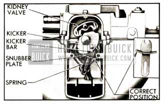
- Remove cover and gasket from face of wiper motor, remove the kidney valve with needle nose pliers, then remove the kicker, kicker bar, and spring. See figure 13-13.
1952 Buick Wiper Motor Valve Parts
- Carefully examine the kicker bar. A broken bar would make the motor inoperative. This breakage is usually caused by incorrect installation of the snubber plate on the kick bar.
- Discard a broken kicker bar, and use a new bar and snubber plate, which may be obtained from United Motor Service in a Trico Service Kit No. 4905A. Install the new snubber plate on the kicker bar with the ends curved toward the notched end of bar. See figure 13-13.
- Check the tube on which the kidney valve is mounted. If the tube protrudes more than 1/8″ from surface of valve body, press the tube into valve body to this dimension. With tube protruding 1/8″, it must be a snug fit in valve body. If tube is loose enough to be jiggled with fingers the wiper motor should be replaced.
- Wipe all dirt and lubricant from surfaces of kidney valve, valve body behind valve, and valve cover.
- Apply a thin coating of “Trico WiperLube” to face of kidney valve that contacts the valve body. This lubricant is available at UMS Service Stations.
- Install spring, kicker bar with snubber plate, kicker, and kidney valve. See figure 13-13. Install cover and gasket.
- Install wiper motor if removed from car, then check motor operation.
Replacement of 1952 Buick Windshield Wiper Control
- Loosen clamp screw and disconnect control cable from valve on 1952 Buick windshield wiper motor.
- On Series 50-70 only, disconnect battery ground cable, then remove fuse block from instrument panel.
- Carefully pry control knob rearward to remove it from control valve shaft, to which it is retained by a small spring.
- Using special socket wrench shown in figure 13-14 remove control nut and internal-tooth lockwasher then remove control from instrument panel. Disconnect 1952 Buick windshield washer hoses if attached to control.
1952 Buick Control and Transmission Nut Socket Wrench
- When reversing above procedure to install the control, adjust the control cable at clamp screw on wiper motor so that valve is fully opened when control knob is at “ON” position. On Series 50-70, install fuse block then connect battery ground cable in proper manner to wind the clock (par. 10-66).
1952 Buick Series 40 Windshield Wiper Transmission Removal and Installation
- Remove wiper blade and arm from transmission shaft.
- Remove defroster hose, glove box and defroster housing as required to reach the 1952 Buick windshield wiper motor and the transmission to be removed.
- Disconnect transmission link at wiper motor. The spring connected washers of the link retainer have key hole slots for engagement with grooves in link pins on wiper motor lever.
- Disconnect 1952 Buick windshield washer hose from transmission.
- Remove bolt and retainer which anchor the transmission on underside of cowl, then remove transmission and gasket from outside of body, threading the attached link up through hole in cowl.
- When transmission is installed by reversing the procedure for removal, seal the gasket with 3-M Autobody Sealer but use care to keep sealer away from windshield washer hose connection. Connect the right transmission link to the upper pin and the left link to lower pin on the wiper motor lever.
- Before installing wiper arm and blade, operate the 1952 Buick windshield wiper and then stop it to obtain the proper parked position. Install arm and blade so that blade just clears windshield glass rubber channel in parked position.
1952 Buick Series 50-70 Windshield Wiper Transmission Removal and Installation
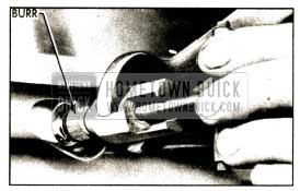
- Remove wiper blade and arm from driving burr on wiper transmission shaft.
- Remove adapter screw from handle of Burr Remover and Replacer J 2682 and thread in into the end of transmission shaft, then install the tool so that clutch end of barrel grips the underside of driving burr. Hold the barrel of tool stationary with an open end wrench, turn handle of tool counterclockwise until burr is removed. See figure 13-15.
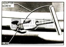
1952 Buick Removing Driving Burr from Transmission Shaft
- Remove transmission nut using special socket wrench shown in figure 13-14. Remove 1952 Buick windshield washer nut and nozzle, then remove escutcheon.
- Working under instrument panel, disconnect windshield washer hose. For removal of right hand transmission also remove the glove box.
- Apply slight pressure to cable tensioner ratchet spring, then rotate pulley support plate until a 1/8″ pin can be inserted through the holes in plate and bracket to remove spring pressure from the cables. See figure 13-16. Disconnect cables from drive shaft lever.
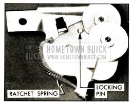
1952 Buick Cable Tensioner
- Remove two attaching bolts and lower the transmission out of position and remove.
- Install 1952 Buick windshield wiper transmission by reversing procedure for removal, observing the following points:
- Before installing transmission coat the shaft with liquid soap to aid in inserting it through the 1952 Buick windshield glass channel.
- When connecting the transmission cables to drive shaft lever, attach the right hand end of cable to upper end of drive shaft lever, and attach left hand end to lower end of lever. Pass the right hand loop of cable over the upper pulley on cable tensioner and pass the left hand loop over the lower pulley.
- While holding cables in pulleys, apply slight pressure to cable tensioner ratchet spring and rotate pulley support plate to remove pressure from temporary locking pin which will then fall out of holes. Slowly release pulley support plate until cables are tight, then release ratchet spring. CAUTION: Do not let pulleys snap against cables.
- Before installation of escutcheon and nut apply 3-M Autobody Sealer around base of wiper shaft and washer outlet.
- Always install a new driving burr on upper end of transmission shaft and use Remover and Replacer J 2682 to press it into position. The bore of a new burr is not serrated; the splined shaft cuts serrations in the softer metal of burr during installation.
- Reverse the barrel on handle of tool J 2682 so that tapered end of barrel is toward threaded pilot of handle. Carefully place new driving burr on shaft so that it is squarely aligned, then screw the threaded pilot of tool handle into end of transmission shaft.
- Holding handle of tool stationary, carefully and gradually turn the barrel counterclockwise with an open end wrench until the driving burr has been pressed flush with end of shaft. See figure 13-17.
1952 Buick Installing Driving Burr on Transmission Shaft
- Before installing wiper arm and blade, operate the 1952 Buick windshield wiper and then stop it to obtain the proper parked position. Install arm and blade so that blade just clears windshield glass rubber channel in parked position.
13-11 1952 BUICK BELT, HEADER, AND REVEAL MOLDINGS
IMPORTANT: Belt, header, and reveal moldings must not be pried loose as they are retained by clips and bolt type retainers.
This paragraph contains replacement information on the various types of external moldings at 1952 Buick windshield and back window openings.
Replacement of Front End Belt Molding
The Series 40 front end belt molding consists of three sections held in place by the overlapping 1952 Buick windshield wiper transmissions and by bolt type retainers. A rubber sealing washer and a plain washer are placed over each retainer bolt under the cowl before the nut is installed.
The Series 50-70 front end belt molding consists of two sections, with right hand section overlapping the left hand section at the center. Three bolt type retainers attach each section of molding and one retainer attaches both sections where they overlap at the center. Rubber sealing washers are placed on each retainer bolt between the molding and cowl panel. See figure 13-18. A single screw attaches outer end of each molding to the body pillar.
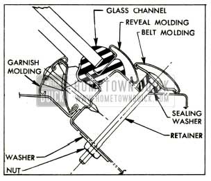
1952 Buick Series 50-70 Belt, Reveal, and Garnish Moldings at Bottom of Windshield
- Remove both wiper blades and arms from 1952 Buick windshield wiper transmission shaft.
- On Series 50-70 remove driving burrs, nuts, and escutcheons from 1952 Buick windshield wiper transmissions (par. 13-10, e). Remove screws attaching ends of belt molding to body pillars.
- Remove glove box and defroster parts to provide access to belt molding retainer bolt nuts under cowl.
- On Series 40 only, remove both windshield wiper transmission retainers. On all series, remove nuts and washers from belt molding retainer bolts.
- Remove belt molding sections and retainers from outside body. On Series 40, raise wiper transmissions far enough to release the moldings.
- Before installing belt molding on Series 50-70, place sealing washers on retainer bolts, then apply 3-M Weatherstrip Adhesive to bolts around the sealing washers. On all series, apply adhesive to bolt holes in cowl.
- Install belt molding and other parts by reversing removal procedure. On Series 40 make sure that a sealing washer is located at each retainer bolt under cowl and is well sealed.
Replacement of 1952 Buick Windshield Header Molding
The right hand section of 1952 Buick windshield header molding overlaps the left hand section at the center. The sections are attached by six bolt type retainers having barrel nuts located in the windshield header under the headlining. Rubber sealing washers are placed on retainer bolts between the molding and roof panel. See figure 13-19. A single screw attaches outer end of each molding to the body pillar.
1952 Buick Sectional View of Windshield Header Molding Installation
- Remove screws attaching ends of molding to body pillar.
- Remove rear view mirror. Remove escutcheon, both windshield garnish molding sections and the defroster air deflectors attached to moldings with clips. NOTE: When removing right garnish molding, detach radio antenna lead-in cable by removing clips which attach cable to molding.
- Loosen headlining along windshield header and through openings in header remove the six barrel nuts from header molding retainer bolts.
- Remove header molding with retainers and sealing washers from outside of body.
- Before installing header molding, place sealing washers on retainer bolts, then apply 3-M Weatherstrip Adhesive to bolt holes and to bolts around the sealing washers.
- Install header molding, place barrel nuts on retainer bolts and tighten firmly. Apply adhesive to screw holes at outer ends of molding sections and install attaching screws.
- Tack headlining to windshield header and install garnish molding and rear view mirror. NOTE: When installing right garnish molding, attach antenna lead-in cable to molding with clips as d e scribed in paragraph 11-9 (b, step 7).
Replacement of 1952 Buick Windshield Reveal and Center Division Moldings
1952 Buick windshield reveal moldings are attached by a flange inserted into a groove of the windshield glass rubber channel. They cannot be replaced except when the windshield glass and channel assembly is removed from body opening as described in paragraph 13-12.
The 1952 Buick windshield outer division molding used with two piece windshields is retained by barrel nuts in the inner division molding. The lower end of outer molding is retained by the front end belt molding.
To remove outer division molding, remove belt molding retainer nut and washer at center of body under instrument panel, remove barrel nuts from inner division molding, then remove outer molding. Before installing molding, seal around molding retaining screw holes on glass rubber channel with 3-M Autobody Sealer.
Replacement of 1952 Buick Back Window Reveal Moldings
Reveal moldings on the one-piece back windows, and upper reveal moldings on the three-piece back windows, are retained by bolt type retainers. Corner angle moldings, where used, are attached by bolt type retainers. Retainer bolt nuts can be reached by removing the back window garnish molding.
Lower reveal moldings on three-piece back windows are retained by clips inserted into grooves in the window glass rubber channel.
Clipped moldings can only be replaced after the glass and channel assembly is removed from window opening as described in paragraph 13-13.
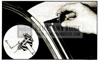
Use new retainers when installing reveal molding, since old ones have been cut off after installation. Place retainers in molding with short side of plate toward the inner or glass side of molding. See figure 13-20.
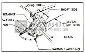
1952 Buick Reveal Molding Retainer Installation
Seal retainer bolts with 3-M Weatherstrip Adhesive before installation of molding. After installation, draw nuts up firmly then cut off surplus ends of bolts to provide clearance when garnish molding is installed.
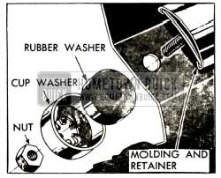
Replacement of Rear End or Quarter Belt Moldings
Except on Convertible bodies, the molding sections are attached across the back by bolt type retainers fitted with rubber washers, cup washers and nuts which are accessible in the rear compartment. Tt forward ends of molding are attached by snap-on type retainers bolted to the rear quarter panel, except in Style “19” which uses the bolt type retainers.
On Convertible bodies the rear end belt molding is attached by a snap-on retainer at front end and by the screws which attach the top boot fasteners over the molding. To remove molding, remove boot fasteners and carefully lift molding clear of retainer at front end.
On bodies other than Convertible, remove rear end belt molding as follows:
- Open rear compartment lid and remove the compartment sidewall trim where this is necessary to provide access to the molding retainer bolt nuts.
- Remove all nuts, cup washers and rubber washers from belt molding retainer bolts in rear compartment. See figure 13-21.
1952 Buick Bolt Type Belt Molding Retainer
- Except on Style “19” body, carefully detach front portion of belt molding sections from the snap-on retainers along each rear quarter outer panel, and remove molding. Use care to avoid bending molding or damaging adjacent body finish. See figure 13-22.
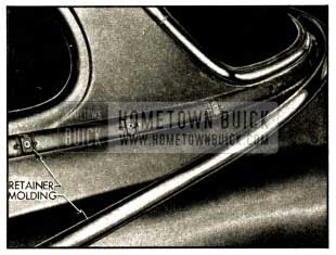
1952 Buick Belt Molding Snap-On Retainers
On Style “19” body, remove rear quarter trim far enough to uncover the inspection hole in rear quarter inner panel. Through inspection hole, remove nut, cup washer, and rubber washer from belt molding retainer bolt, then remove molding from body.
- Install belt molding by reversing the procedure for removal. Seal around each bolt hole with 3-M Autobody Sealer before molding is placed in position.
13-12 1952 BUICK WINDSHIELD GLASS REPLACEMENT
The 1952 Buick windshield glass is mounted in a molded rubber channel which fits over a pinchweld flange formed by the body panels around the windshield opening. The joints between the rubber channel, the glass, and the pinchweld flange are sealed with compound to prevent leakage of water.
The reveal moldings which cover the outer sides of the rubber channel have flanges which hook into grooves in the channel. Where corner reveal moldings are used they are attached by bolts with nuts located under the inside edge of the channel. Some models have a header molding which partly covers the upper reveal molding and must be removed when a 1952 Buick windshield glass is replaced.
On Series 40 models, the front end belt molding does not cover the lower reveal molding enough to interfere with replacement of the glass and rubber channel. On Series 50-70 models, the front end belt molding covers the lower reveal molding far enough to make its removal necessary before the glass and channel can be completely removed from the body. As described later, the glass may be replaced without disturbing the belt molding and lower side of the rubber channel.
Removal of 1952 Buick Windshield Glass
- Place suitable coverings over hood, front fenders, and instrument panel to protect finish. Also apply masking tape adjacent to 1952 Buick windshield assembly to cover any exposed finish on upper front body pillars and roof panel of car in the working area.
- Remove rear view mirror. On a model where the rear view mirror bracket forms the inside escutcheon for the radio antenna control, remove the radio antenna (par. 11-9, c).
- Remove 1952 Buick windshield garnish molding.
NOTE: When removing right garnish molding, detach radio antenna lead-in cable by removing clips which attach cable to molding.
On a 2-piece windshield also remove the inner and outer division moldings.
- On Series 40 only, turn back the pillar trim along sides of windshield opening by first loosening front edge of trim assembly from its cemented attachment to the metal retainer and turning trim and foundation back to clear channel. The metal retainer need not be disturbed. On Riviera and Convertible bodies also loosen and turn back the windshield header trim to provide access to the windshield rubber channel.
- If replacing only one glass of a 2-piece windshield, mask the painted surface adjacent to upper reveal molding directly above the windshield division bar, then raise the reveal molding sufficiently to insert small metal protective shields under edges of molding. Using a hacksaw, carefully cut through the flat portion of the molding at the exact center of the division bar. See figure 13-23.
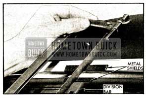
1952 Buick Cutting Upper Reveal Moldlng-2 Piece Windshield
- Remove 1952 Buick windshield header molding if present (par. 13-11, b).
- Remove escutcheon at radio antenna and reveal molding corner escutcheons, if present. Each corner escutcheon is attached by a bolt running through the glass channel with nut and washer inside the body, See figure 13-24.
1952 Buick Reveal Molding Corner Escutcheon
- Remove door rain deflectors if present, and remove any screws that attach side reveal moldings to body pillars.
- On Series 40 Riviera or Convertible body, loosen both windshield wiper transmissions, then remove both end sections of front end belt molding by removing attaching nuts under cowl and sliding moldings from retainers at outer ends.
On Series 50-70, remove the front end belt molding (par. 13-11, a) only if the complete windshield and rubber channel assembly is to be removed. This is not necessary for replacement of 1952 Buick windshield glass only.
- Use a putty knife to break the seal between the rubber channel and the pinchweld flange. On Series 40 one-piece windshield, break the seal all around the channel. On Series 40 2-piece windshield break the seal along top and side only of glass being removed.
On Series 50-70, break the seal along the top and sides and avoid disturbing the sealing along the bottom unless the complete glass and channel assembly is to be removed.
- With a helper stationed on the outside of the body, carefully force the glass and channel outward with palm of hand against inside surface of glass, starting at either upper corner and working across top of assembly as the separation of channel lip from pinchweld flange progresses.
- On Series 40 one-piece windshield, disengage the glass and channel assembly from body opening and place it on a protected bench, then remove reveal moldings and glass from rubber channel.
On Series 40 2-piece windshield, or Series 50-70 windshield, block upper corner of glass to hold it away from the opening. Slide the upper and side reveal moldings out of rubber channel, loosen the seal between the glass and outer lip of channel and remove the glass.
Installation of 1952 Buick Windshield Glass
After removal of old sealing compound and inspection of the rubber channel and pinchweld flange, the installation is generally the reverse of removal, with particular attention being paid to proper sealing to avoid water leaks.
- If the glass rubber channel was sealed with the original factory compound which has a neutral color, clean sealing compound from the pinchweld flange with a putty knife or a dry rag. It is not necessary to remove this sealer from the rubber channel. Do not use solvents (oleum spirits, gasoline, etc.) to clean off this type of sealing compound.
If the glass rubber channel has been previously reset with one of the black sealing compounds used in service, it may be necessary to use oleum spirits or a similar solvent to clean off the old compound.
- Carefully check the pinchweld flange for high spots which would impart a strain on the glass. Correct any irregularities by filing or hammering the flange.
- If the rubber channel was not removed, apply a mild soap solution in the glass and reveal molding cavities of channel, then place the new glass in position and fold the lip of channel over edge of glass all around its perimeter. Do not pry against edge of glass with a metal tool. Install side and top reveal moldings in grooves of channel.
If the rubber channel was removed, assemble the new glass and channel on a bench, as follows:
- Install rubber channel over edge of glass with the glass trade mark at lower corner of channel.
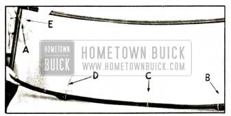
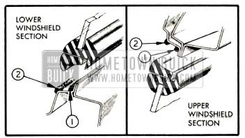
- Insert a strong cord into the pinchweld groove of rubber channel. Referring to figure 13-25, start at upper corner indicated at “A,” then follow across the top, down the side, and along the bottom to the wiper shaft location.
1952 Buick Assembly of Glass and Rubber Channel
At this point, make a loop in the cord and into this loop insert a short section of cord indicated at “B.” At bottom center of long cord make another loop indicated at “C.” At opposite wiper section of channel indicated at “D” loop the cord and insert another short section. Follow up the remaining side and cross both ends of the cord at the upper corner indicated at “E.” Tape ends of cord to inside surface of glass as illustrated.
- Insert the flange of reveal moldings into the groove in rubber channel. See sectional view in figure 13-18.
- Apply continuous bead of 3-M Autobody Sealer around the windshield opening at (1) outer corner of pinchweld flange and (2) outer corner of windshield opening rabbet as indicated in figure 13-26. On two-piece windshield also apply a bead of sealer across the top and bottom of windshield center division bar.
1952 Buick Location of Windshield Sealing Compounds
- While a helper on the outside holds the glass and rubber channel firmly in position in body opening, work on the inside to fold the lip of rubber channel over the pinchweld flange. If a cord was installed as described above, pull on the cord to fold lip of channel over flange as cord is removed. Use care to avoid tearing the channel, and make certain that it is fully seated all around the pinchweld flange.
- Using trigger gun B 182-A, apply 3-M Weatherstrip Adhesive between outer lip of rubber channel and the glass all around the channel; also apply adhesive around the shaft and washer outlet of wiper transmission (Series 50-70).
- Complete the installation by reversing the procedures for removal of the remaining parts. Use 3-M Autobody Sealer to seal around molding escutcheons and bolts, and along mounting edge of Riviera door rain deflectors if present. Use 3-M Weatherstrip Adhesive to seal screw holes and other points where a lighter bodied sealer is required.
NOTE: When installing right garnish molding, attach antenna lead-in cable to molding with clips as d escribed in paragraph 11-9 (b, step 7). If radio antenna was removed, reinstall antenna as described in paragraph 11-9 (c).
On a 2-piece windshield on which the upper reveal molding has been cut at the center, make certain that the cut ends of molding are together and are covered by the upper end of the outer division molding.
13-13 1952 BUICK BACK WINDOW GLASS REPLACEMENT
1952 Buick back window glasses are mounted in a molded rubber channel which fits over a pinchweld flange formed by the body panels around the window opening.
The reveal molding which covers the rubber channel on the outside is retained by bolts and in some cases by clips which engage a groove in the rubber channel.
The procedure for removal, installation and sealing of a back window glass is essentially the same on all models, with the exception of variations caused by differences in the reveal moldings.
Removal of Back Window Glass Assembly
- Apply masking tape around back window opening and place protective covers where necessary to protect finish and trim.
- Remove rear seat cushion. On styles where the seat back interferes with removal of window garnish molding remove the seat back.
If body has a center arm rest, remove arm rest extension strap retainer by removing two screws concealed under upper end of strap, then remove seat back trim valance by removing all screws attaching it to the shelf panel.
- Remove window garnish molding; also remove inner division moldings on 3-piece window.
- On styles where the rear end belt molding overlaps the window lower reveal molding or lower corner reveal molding, remove the belt molding (par. 3-11, d).
On Style “19” remove ventilator header moldings (par. 13-18).
- On inside of body remove nuts from all reveal molding retainer bolts, located under the lip of the rubber glass channel.
- On outside of body remove outer division moldings (3-piece window) and all bolted sections of reveal molding. Mark location of retainer bolt holes on masking tape around window opening to aid in reinstallation. Do not pry on reveal molding sections which are retained by clips instead of bolts.
- With a flat blade tool, loosen the rubber channel from sealer around opening, then with a helper stationed on outside of body, apply moderate hand pressure against the glass from inside the body and carefully force the glass and its channel to release from the pinchweld flange. Start at one side and work across top of assembly to opposite side.
- From outside of body with the aid of a helper, grasp each end of loose back window assembly, lift up and remove assembly from opening.
- Place glass and channel assembly on a covered bench. Remove clipped type reveal molding, if present, then carefully disengage rubber channel from glass sections. Do not pry edges of glass with a metal tool.
Installation of Back Window Glass Assembly
- If the glass rubber channel was sealed with the original factory compound which has a neutral color, clean sealing compound from the pinchweld flange with a putty knife or a dry cloth. It is not necessary to remove this sealer from the rubber channel. Do not use solvents (oleum spirits, gasoline, etc.) to clean off this type of sealing compound.
If the glass rubber channel has been previously reset with one of the black sealing compounds used in service, it may be necessary to use oleum spirits or a similar solvent to clean off the old compound.
- Carefully check the pinchweld flange for high spots which would impart a strain on the glasses. Use glasses for templates to check flange for proper contour. Correct any irregularities by filing or hammering.
- On a covered bench, install window glass in the rubber channel, making sure that the etched trade mark on glass is at bottom of the assembly. Using a mild soap solution in groove of rubber channel will aid installation. Do not pry on edges of glass with a metal tool.
On three-piece back window, install the center section in rubber channel first, then install the side sections.
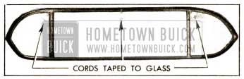
- Insert strong cords into the pinchweld and division bar grooves of rubber channel around each individual section of glass. Tie each cord snugly and tape ends to inside surface of glass. See figure 13-27.
1952 Buick Channel and Cords Installed on Glasses
- Install reveal molding sections which are retained by clips by inserting the clips into the groove in rubber channel.
- Apply continuous beads of 3-M Autobody Sealer completely around the window opening at outer corner of pinchweld flange and outer corner of window opening rabbet as shown for 1952 Buick windshield in figure 13-26.
- With a helper, place glass assembly in window opening and align bolt holes in channel with marks previously made on masking tape. While helper holds glass assembly firmly in place, pull out the cords on inside to fold the lip of rubber channel over the pinchweld and division bar flanges.
- Using trigger gun B 182-A, apply 3-M Weatherstrip Adhesive under outer lip of rubber channel all around each glass section.
- Insert retainers into bolted type rev al molding sections. The short side of retainer plate must be placed toward inner or glass side of molding. See figure 13-20.
- Apply 3-M Autobody Sealer around all bolt holes in rubber channel, then install all reveal molding sections and the outer division moldings (3 piece window).
- On inside of body, install washers and nuts on reveal molding retainer bolts and draw up to a snug fit. Cut off excess ends of bolts to permit lip of rubber channel to cover the nuts.
- Complete the installation by reinstalling the remaining moldings and other parts removed, paying attention to the following items:
- Seal and install ventilator header moldings as described in paragraph 13-18.
- Seal and install rear end belt molding as described in paragraph 13-11 (d).
- Clean off all excess sealer and remove protective covering.
Leave A Comment
You must be logged in to post a comment.