SECTION 7-B 1952 BUICK POWER STEERING GEAR AND PUMP
7-9 1952 BUICK POWER STEERING GEAR AND PUMP SPECIFICATIONS
Tightening Specifications
Use a reliable torque wrench to tighten the parts listed to insure proper tightness without straining or distorting parts. These specifications are for clean and lightly lubricated threads only: dry or dirty threads produce increased friction which prevents accurate measurement of tightness.
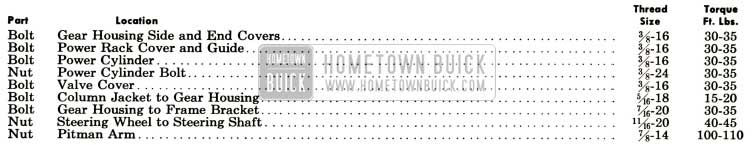
1952 Buick Power Steering Gear Tightening Specifications
1952 Buick Power Steering Gear Specifications
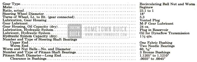
1952 Buick Power Steering Gear Specifications
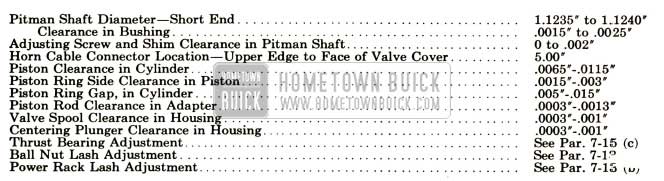
1952 Buick Power Steering Gear Specification
1952 Buick Power Steering Pump Specifications
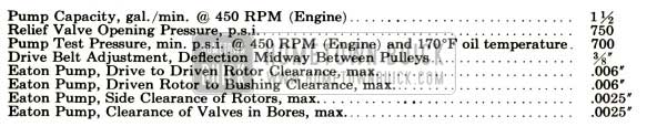
1952 Buick Power Steering Pump Specifications
7-10 DESCRIPTION OF 1952 BUICK POWER STEERING GEAR AND PUMP
1952 Buick Power Steering, available as optional equipment on Series 70, consists of a conventional manually operated steering gear to which hydraulic power mechanism has been added. The hydraulic mechanism furnishes additional power to ASSIST the manual operation so that the turning effort required at steering wheel is greatly reduced.
The engine drives the oil pump which furnishes hydraulic pressure. When the engine is not running, or when any part of the power mechanism is ‘inoperative, steering is entirely manual and requires approximately the same effort at the steering wheel as the manual gear used as standard equipment.
With the engine running, steering is entirely manual under conditions which requires an effort of less than four pounds at the steering wheel rim. When a greater effort is required, the power mechanism operates to ASSIST in turning the front wheels. The effort then required at steering wheel rim is thereby limited to a maximum of approximately nine pounds for normal steering and parking conditions, compared to possibly fifty pounds with the standard manual gear. If some abnormal condition requires more work than the power mechanism can do, the driver must assist with increased effort at the steering wheel.
The driver’s effort on the steering wheel is always proportional to the force necessary to turn the front wheels. When the effort on the wheel drops to less than four pounds as the turn is completed, power assistance ceases. When the wheel is released to recover from the turn, the front wheels may return to the straight ahead position in the usual manner without assistance or interference from the power mechanism. Through this conventional steering action the driver always has the “feel” of steering which is essential to confidence in controlling the direction of the car.
It should be noted that 1952 Buick power steering always follows the manual steering action. No steering action is obtained except through the manual guidance of the driver.
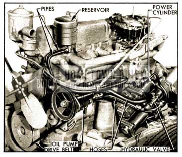
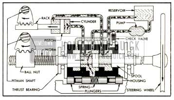
The hydraulic power mechanism added to the steering gear includes a power cylinder and rack connected to a separate gear sector on the steering gear pitman shaft, a hydraulic valve mounted concentric with the steering worm shaft and operated by the shaft, a high pressure oil pump driven by a belt from the engine, an oil reservoir, and connecting pipes and hoses. See figure 7-14.
1952 Buick Power Steering Gear and Pump Installation
The hydraulic units are filled with the same oil as specified for Dynaflow transmissions. The 1952 Buick Power steering gear housing is filled with regular steering gear lubricant.
1952 Buick Power Steering Gear Assembly
The 1952 Buick power steering gear assembly is the recirculating ball nut and worm type, having a ratio of 21.3 to 1.
1952 Buick Power Steering Gear Assembly
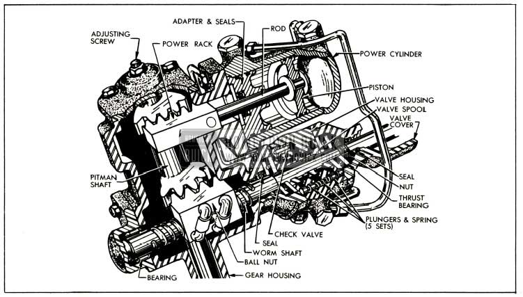
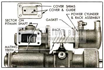
As shown in figure 7-15, the upper end of the pitman shaft is extended and provided with a separate gear sector which meshes with a power rack mounted in the gear housing. The power rack is pinned to the piston rod of the power cylinder, mounted on the rear side of gear housing, and is held in proper mesh with the pitman shaft sector by a guide attached to a shim adjusted housing cover (not shown).
The 1952 Buick power cylinder is a double acting type since oil pressure may be applied to either side of the piston through external tubes connected to the hydraulic valve, described below (subpar. b). An adapter closes the inner end of the cylinder and provides a bearing for the piston rod. The two outer grooves in the circumference of the adapter contain „O“ ring rubber seals, and the bore is fitted with a spring loaded rubber seal to prevent escape of oil at piston rod. See figure 7-15. Normal seepage of oil through the bearing is bled back to the hydraulic valve through passages in adapter and cylinder connected to an external tube.
The upper end of steering shaft is supported by a steel jacketed prelubricated bearing (bushing) mounted in signal switch housing. The lower (worm) end of shaft is supported in gear housing by two needle bearings. These bearings permit axial (endwise) movement of the shaft.
Axial movement of the steering shaft is opposed by two flat thrust bearings in conjunction with centering springs and plungers contained in the hydraulic valve. One thrust bearing butts against a shoulder and the other bearing is retained by a threaded nut on the worm section of steering shaft. The inner races of both bearings contact the valve centering plungers which are under pressure of the centering springs. See figure 7-15.
Axial movement of the steering shaft under load is limited to approximately .030″ either way from the neutral (no load) position by the clearance between the thrust bearings and the hydraulic valve housing. This axial movement is used to operate the hydraulic valve.
Hydraulic Valve
The hydraulic valve controls the flow of oil from the pump to the proper side of the power cylinder piston when power assistance is required and cuts off this flow when power assistance is not required. It also regulates the effort at steering wheel within the normal range of four to nine pounds so that this effort is proportional to the force necessary to turn the front wheels, thereby providing the “feel” of steering previously mentioned.
All parts are contained in the valve housing which is mounted on the 1952 Buick Power steering gear housing and is concentric with the steering worm shaft.
The housing has one central annular groove connected to the oil pump and two outer annular grooves connected to the reservoir.
A valve spool, having a very close sliding fit in valve housing, is mounted concentric with the worm shaft and between the worm thrust bearings so that it moves with these parts. The spool contains two annular grooves which control the flow of oil between the grooves and oil passages in valve housing. See figure 7-15.
The housing contains five equally spaced pairs of centering plungers which are forced outward against the gear housing and the valve cover by a heavy coil spring located between the plungers. As previously explained, the worm thrust bearings contact the plungers so that axial movement of the worm shaft is opposed by the plungers and springs.
The worm shaft and thrust bearings will move the spool endwise in the valve housing, permitting oil flow to the power cylinder, whenever the thrust load on the worm shaft is sufficient to overcome the preload of the centering springs. The resulting control of the power mechanism will be fully explained in paragraph 7-11.
The check valve located in the hydraulic valve housing permits the oil displaced by the power cylinder piston to bypass the oil pump during manual operation whenever the oil pump is not operating. It also prevents oil from overflowing through the reservoir vent under the same conditions.
1952 Buick Oil Pump
The oil pump, which is mounted on the engine in position to be driven by a belt from the crankshaft balancer, converts some engine power into oil pressure which is used by the power cylinder and rack to rotate the pitman shaft.
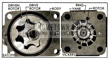
The Eaton rotor pump and the Vickers balanced vane pump are optionally used, to assure adequate supply for production and service.
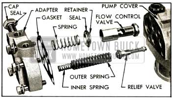
The Eaton pump houses a drive rotor meshed with a driven rotor which rotates on a different center. As these parts rotate the pockets formed between them increase and then decrease to propel the oil from entrance to exit ports of pump. See figure 7-16.
1952 Buick Eaton and Vicken Pumping Elements
The Vickers pump houses a slotted driving hub or rotor in which twelve vanes slide radially outward to contact the hardened and ground inside surface of a ring. As the shaft and rotor rotates, centrifugal force and fluid pressure against the inner ends cause the vanes to follow the cam contour of the ring, which is so shaped that two opposing pumping chambers are formed. In each pumping chamber, the increasing and decreasing pockets formed between the rotor, vanes, and ring propel the oil from the entrance to the exit ports of pump. See figure 7-16.
Both optional pumps contain an overload relief valve which is set to open at 750 p.s.i. and a flow control valve which recirculates oil within the pump as required to regulate the output volume to approximately 1 1/2 gallons per minute at all operating speeds.
Reservoir, Pipes, and Hoses
The reservoir is mounted on the engine at a higher level than the pump. See figure 7-14. It contains a fine mesh screen of large area. The filler plug is vented and is provided with an oil level gauge rod. The reservoir provides a reserve supply of oil to assure complete filling of the hydraulic system and the vented filler plug permits escape of any air that may be introduced into the system during assembly of the various units.
Two pipes provided with flexible hoses connect the reservoir to the oil pump. A pressure line hose and a return line hose connects the oil pump to the hydraulic valve. See figure 7-14. The pressure line hose is reduced in size at the valve end to provide a dampening effect on any turbulence in the oil stream. The same hoses are used with the Eaton and Vickers oil pump, but the small reservoir inlet pipe and hose assembly is different for each pump.
7-11 OPERATION OF 1952 BUICK HYDRAULIC POWER MECHANISM
When the 1952 Buick steering wheel is turned, the ball nut must move axially along the worm shaft in order to rotate the pitman shaft and thereby turn the front wheels through the connecting linkage. Movement of the ball nut is opposed by the force necessary to turn the front wheels, consequently the worm shaft tends to move endwise through the ball nut. The ball nut and worm shaft act like a screw jack to thrust a load against one worm thrust bearing, tending to move the bearing.
Movement of the thrust bearing (and worm shaft) is opposed by the centering plungers and springs in the hydraulic valve, therefore the thrust load must exceed the 300 pound total preload of the five centering springs before the worm shaft can actually move endwise. A pull of four pounds on the steering wheel rim produces a thrust load of 300 pounds, consequently the worm shaft will move endwise only when the force necessary to turn the front wheels requires an effort of more than four pounds at the steering wheel.
Since movement of the hydraulic valve spool is controlled by the worm shaft and thrust bearings it remains in the neutral or centered position in valve housing whenever the effort applied to steering wheel is less than four pounds. In this case the oil merely circulates from the pump through the valve and reservoir without having any effect on the steering operation. See figure 7-17.
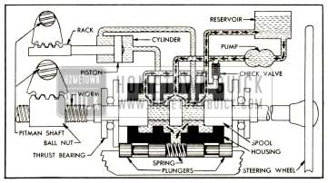
1952 Buick Oil Circulation Without Power Application
Although the power cylinder is filled with oil there is no interference with manual steering because the oil displaced by the piston can flow from one side of the piston to the other through the hydraulic valve.
When the steering wheel is turned left with an effort greater than four pounds, the resulting thrust load compresses the centering springs and the worm shaft moves the spool upward in the valve housing. The spool then routes the oil flow from the pump into the upper end of the power cylinder. The passage to the lower end of power cylinder is left open for return of oil to the reservoir. See figure 7-18.
1952 Buick Oil Circulation During Power Application on a Left Turn
Flow of oil into the power cylinder is resisted by the piston because of its connection to the pitman shaft. The oil pump then builds up just enough pressure to overcome this resistance so that just enough power is applied to rotate the pitman shaft.
Since the pitman shaft is also geared to the ball nut on the worm shaft it is obvious that the pitman shaft cannot turn unless the steering wheel is also turned. Thus, 1952 Buick power steering cannot be applied without manual steering.
As the pump pressure builds up, oil pressure is also directed against the inner ends of the centering plungers. This pressure, added to the centering spring preload, tends to force the spool back to the neutral position. Since the pump pressure builds up in proportion to the force necessary to turn the front wheels, the corresponding pressure on the plungers creates a reaction that must be overcome by effort on the steering wheel. In this way, the effort required at the steering wheel is regulated in proportion to the resistance of the front wheels, giving the “feel” of steering previously mentioned.
The effort on the steering wheel naturally drops to less than four pounds as the turn is completed; therefore the centering springs and plungers return the valve spool to the centered position, thereby cutting off application of oil pressure to the power cylinder. When the spool returns to the centered position, steering becomes entirely manual. The oil merely circulates through the hydraulic valve as shown in figure 7-17 and the oil pressure drops because there is virtually no resistance to oil flow.
1952 Buick power steering on a right turn is accomplished in the manner described except that the worm thrust is in the opposite direction, therefore the valve spool moves down to route oil to the lower end of the power cylinder so that power will be applied to turn the pitman shaft in the opposite direction.
When the front wheels strike an obstruction which kicks them to the left, the force is transmitted through the steering linkage and pitman shaft to exert a downward thrust on the ball nut and worm shaft; this is opposite to the direction of thrust when the steering wheel is turned left. If the thrust load exceeds 300 pounds, the valve spool will move down to route oil flow to the lower end of power cylinder, thereby applying opposing power to counteract the leftward movement of the front wheels. The opposite action occurs when the wheels are kicked to the right. In this manner, the power mechanism counteracts road shock before it is transmitted to the steering wheel.
The check valve located in the hydraulic valve housing remains closed when the oil pump is operating. When the oil pump is not operating and the steering gear is operated manually, the oil displaced by the power cylinder piston flows through the check valve and back into the central groove of valve housing without passing through the reservoir and pump. The oil bypasses the pump which would obstruct its flow. This feature also prevents overflowing of oil through the reservoir vent.
7-12 TROUBLE DIAGNOSIS – 1952 BUICK POWER STEERING GEAR AND PUMP
This paragraph will cover only those causes of trouble which may be due to the hydraulic power mechanism. Causes which are due to the mechanical components of the steering gear, linkage, and front suspension are the same as described for the standard steering gear in paragraph 7-3.
Before assuming that the hydraulic power mechanism is at fault, make certain that the mechanical components are in proper condition. The mechanical items include: Front wheel alignment, tire condition and pressure, wheel bearing adjustment, lubrication and adjustment of steering linkage, and proper alignment of 1952 Buick Power steering gear in mountings to eliminate binding.
Excessive Play or Looseness in 1952 Buick Power Steering Mechanism
- Excessive lash between pitman shaft sectors and the ball nut or power rack (par. 7-13).
- Loose worm thrust bearing adjustment or sticking valve spool, requiring removal of gear assembly (par. 7-15).
Front Wheel Shimmy
- Air in hydraulic system, requiring bleeding (par. 7-13).
- Excessive lash between pitman shaft sectors and the ball nut or power rack (par. 7-13).
Poor Centering or Recovery from Turns
- Binding of steering shaft due to misalignment of gear in mountings.
- Sticking valve spool or faulty centering springs, requiring removal of gear assembly (par. 7-15).
Rattle or Chuckle in 1952 Buick Power Steering Gear
(1) Excessive lash between pitman shaft sectors and ball nut or power rack (par. 7-13). NOTE: A very slight rattle may occur on turns because of the increased lash off the “high point.” This is normal, and lash must not be reduced below specified limits to eliminate this slight rattle.
Hard Steering When Parking
NOTE: It is a normal condition to feel an increase in parking effort if the hydraulic oil temperature exceeds 170° F. The oil temperature may exceed 170° F after excessive turning or on very hot days.
To determine whether hard steering actually exists, place car on clean dry floor, apply brakes, and with engine idling turn steering wheel from side to side to bring oil temperature to approximately 170° F. Apply Gauge J 5178 (15 lbs.) to a spoke at rim of steering and check the pull required to turn the wheel steadily, with gauge held at 90 degrees to the spoke.
If the pull required to turn the steering wheel exceeds 10 pounds, check the following possible causes:
- Pump drive belt loose. Adjust tension (par. 7-13).
- Low oil level in reservoir. Fill to proper level (par. 1-1). NOTE: If oil level is excessively low, check all hydraulic system lines and joints for evidence of external leakage of oil.
- Air in hydraulic system. Tighten valve cover bolts and all oil line connections on 1952 Buick Power steering gear, pump and reservoir, then bleed the hydraulic system (par. 7-13).
- Insufficient oil pressure. If the preceding suggestions do not reveal the cause of hard steering it will be necessary to make the following tests of oil pressure (subpar. f).
Testing Hydraulic Oil Pressure
- Disconnect the pressure line hose at oil pump, attach Gauge J 5176 to pump and connect the hose to end of gauge where the valve is located. See figure 7-19.
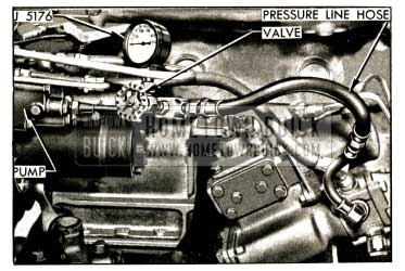
1952 Buick Pressure Gauge J 5176 Installed
- First test (step 2) pressure low, and second test (step 4) pressure normal- indicates faulty external oil lines or steering gear (subpar. g or h).
- First test (step 2) and second test (step 4) pressures equally low -indicates faulty oil pump (subpar i).
- First test (step 2) pressure low, and second test (step 4) pressure higher but below normal indicates faulty pump and also faulty external oil lines or steering gear (subpar. g, h, i).
Low Oil Pressure Due to External Oil Lines
- Loose connections. Clean and tighten all connections and test for oil leakage.
- Leakage at hose unions or oil tube elbows. Remove leaking unions or elbows and install new „O“ ring seals.
Low Oil Pressure Due to 1952 Buick Power Steering Gear
- Leakage at worm shaft seal or cylinder piston rod seal, evidenced by an accumulation of hydraulic oil in gear housing. Leakage at valve cover seal, evidenced by oil dripping from top of valve cover. Remove gear assembly for replacement of seals (par. 7-15).
- Pressure loss in hydraulic valve or power cylinder. Remove gear assembly for disassembly and inspection (par. 7-15).
Low Oil Pressure Due to Pump
- Pump drive belt loose. Adjust tension (par. 7-13).
- Low oil level in reservoir. Fill to proper level (par. 1-1).
- Oil too light. Change to specified Dynaflow oil (par. 1-4).
- Loose pump assemb1y bolts. Tighten all pump bolts.
- Faulty internal pump condition such as dirt or sludge, sticking or scored relief or flow control valve, worn rotor parts, shaft oil seal leakages. Remove pump and disassemble for inspection (par. 7-16, Vickers; par. 7-17, Eaton).
Oil Pump Noisy
- Air in hydraulic system. Tighten all external line connections and bleed hydraulic system (par. 7-13).
- Reservoir air vent plugged. Remove filler plug and clean vent.
- Drive belt too tight. Adjust tension (par. 7-13).
- Oil too heavy. Change to specified Dynaflow oil (par. 1-4).
- Sludge and dirt in pump. Remove pump and clean out (par. 7-16, Vickers; par. 7-17, Eaton).
- Bearings, shaft or other rotating parts worn. Remove pump and disassemble for inspection (par. 7-16, Vickers; par. 7-17, Eaton).
7-13 BLEEDING AND ADJUSTING 1952 BUICK POWER STEERING GEAR ON CAR
Bleeding the Hydraulic System
After a pump or 1952 Buick steering gear is installed, or a disconnected oil line is reconnected, all air that entered the hydraulic system must be bled out, otherwise noisy and unsatisfactory operation will result. While some air will bleed out during operation of the 1952 Buick Power steering gear, this is not dependable; the following procedure must be performed to assure complete elimination of all air.
- After connecting all hoses and filling reservoir to proper level (par. 1-1), let the job set for five minutes with engine shut off. If a Vickers pump is installed, remove pipe plug from top of pump manifold and when oil starts to flow out of opening install plug just tight enough to stop oil .flow, then wait five minutes.
- Start engine and run it at approximately 1000 RPM for two or three minutes, then turn the steering wheel from one extreme to the other until all air is worked out, as evidenced by operation of the oil pump at a normal noise level.
- In some cases it may be necessary to repeat the setting, engine running, and steering operation to eliminate all air. Tighten the plug in Vickers pump manifold when bleeding operations are completed.
- Road test the car with some parking and some high speed driving if possible.
Pump Drive Belt Adjustment
The pump drive belt has proper tension when one side can be depressed%” with thumb pressure applied midway between the pulleys. To adjust belt, loosen pump mounting bolts and move pump horizontally as permitted by the slotted bolt holes in mounting bracket, then tighten bolts securely.
Pitman Shaft to Ball Nut and Power Rack Adjustments
- Disconnect pitman arm from steering tie rod, and check tightness of pitman arm nut with an 18″ wrench. NOTE: N ever attempt to adjust steering gear lash with pitman arm connected to tie rod.
- Turn steering wheel slowly through its full travel to check for binding, which would indicate misalignment of 1952 Buick Power steering gear in its mountings. Any binding due to misalignment must be corrected before adjustments can be properly made.
- Remove filler plug with vent attached (fig. 7-20) and use a clean oil gun to draw out approximately 3/4 pint of lubricant from the gear housing.

1952 Buick Power Steering Gear Adjustments
Record the final scale reading.
- Remove the power rack guide cover (fig. 7-20), take out one .003″ cover shim, then reinstall cover with remaining shims and tighten bolts securely.
- Use scale to check the pull required to turn steering wheel steadily through the “high point” or no-lash range; this should be 1 to 1 1/4, pounds greater than the pull obtained in step 9. Change the total thickness of cover shims as required to obtain this difference.
Shims are available in .003″ and .005″ thicknesses so that they may be combined to produce any required total thickness.
- When the pull obtained in step 11 is 1 to 1 1/4 pounds greater than the pull obtained in step 9, remove the guide cover and add one .003″ shim, then install cover and tighten bolts securely.
- Connect steering tie rod to pitman arm, turn tie rod plug up solid, ten back off two turns and install cotter pin.
Worm Thrust Bearing Adjustment
The worm thrust bearings cannot be properly adjusted with steering gear in car. If it is apparent that this adjustment is required, after making certain that both pitman shaft lash adjustments are correct, the steering gear must be removed so that the thrust bearings can be adjusted as described under Assembly of Steering Gear (par. 7-15, c).
7-14 REMOVAL AND INSTALLATION OF 1952 BUICK POWER STEERING GEAR AND PUMP
Removal and Installation of 1952 Buick Power Steering Gear Assembly
The 1952 Buick power steering gear may be removed and installed by the same procedure as given in paragraph 7-7 for the manual steering gear, with the following additional items:
- Remove pitman arm from pitman shaft, using Puller J 1025. See figure 7-11.
- Remove screws which attach front end of the left air intake duct to the fender skirt and coat rubber grommet on duct with Lubriplate to aid in pulling it through hole in skirt. Disconnect flexible hose at the clamp, reach inside hose and remove bolt that attaches rear end of air duct to rear fender skirt, then remove the air duct.
- Disconnect the pressure and return line hoses from the hydraulic pump and immediately install shipping caps on pump fittings to avoid draining the reservoir. Install shipping plugs in ends of hoses to retain the oil.
- After re-installing gear assembly in mountings, install steering wheel and turn it slowly from one extreme to the other to check for any binding. Readjust gear in mountings if any binding exists. The steering wheel and shaft must turn freely.
- Connect the pressure line hose (marked “PR” on pump end) to the union installed in pump port marked “PR”. On the Eaton pump this union is the one nearest engine but on the Vickers pump it is the one farthest from engine. Connect the return line hose (marked “RT” on pump end) to the remaining union on pump. This pump port is marked “RT”.
- After gear installation is completed fill the reservoir and gear housing to proper levels (par. 1-1), then bleed the hydraulic system (par. 7- 13, a).
Removal and Installation of Oil Pump
- When removing the pump, use shipping plugs and caps to cover the hose connectors and unions on pump and plug open ends of the pressure and return line hose to avoid entrance of dirt.
- When installing the pump, adjust drive belt to proper tension (par. 7-13, b).
- Connect the pressure line hose (marked “PR” on pump end) to the union installed in pump port marked “PR”. On the Eaton pump this union is the one nearest engine but on the Vickers pump it is the one farthest from engine. Connect the return line hose (marked “RT” on pump end) to the remaining union on pump. This pump port is marked “RT”.
- Connect the two reservoir line hoses to pump, then fill reservoir to proper level (par. 1-1) and bleed the hydraulic system (par. 7-13, a).
7-15 DISASSEMBLY, INSPECTION, ASSEMBLY OF 1952 BUICK POWER STEERING GEAR
Disassembly of 1952 Buick Power Steering Gear
- Thoroughly clean exterior of 1952 Buick power steering gear assembly, using care to avoid damaging the finish of the column jacket.
- Remove four bolts which attach the column jacket to the hydraulic valve cover. Slide column jacket and inclosed transmission control shaft from the steering shaft, using care to avoid damaging the upper shaft bearing against the threaded end of shaft.
- Using hot soldering iron, disconnect the horn cable from the cable contact, then remove wire and contact from steering shaft.
- Remove two hoses, two large valve-to cylinder tubes, and the small bleed line tube, then allow oil to drain from hydraulic valve and power cylinder. Remove filler plug with vent and drain lubricant from gear housing. See figure 7-21.
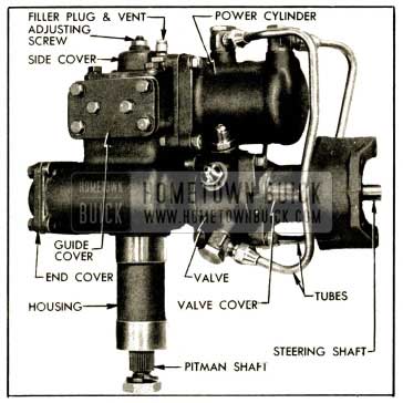
1952 Buick Left Side of Power Steering Gear Assembly
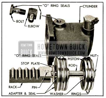
1952 Buick Power Cylinder and Rack Parts
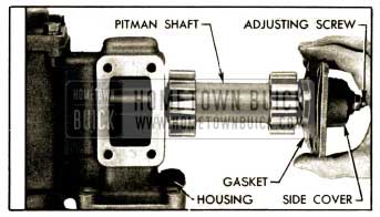
1952 Buick Removing Pitman Shaft and Side Cover
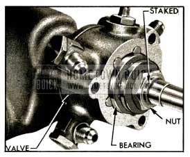
1952 Buick Thrust Bearing and Nut
NOTE: Nuts on first jobs are locked with tangs of a lockwasher.
- With steering shaft horizontal, remove the hydraulic valve assembly, using care to keep the spool and plungers from falling out. Remove lower thrust bearing from gear housing.
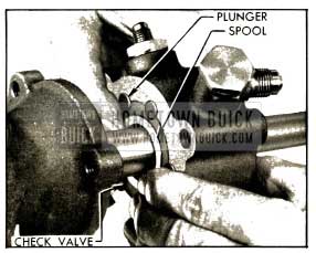
- Check the valve spool and centering plungers for possible sticking in valve housing, then carefully remove these parts and the centering springs. Remove check valve and all unions and elbows. See figure 7-25.
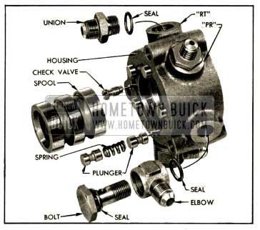
1952 Buick Hydraulic Valve Parts
Place spool and plungers where they will not be damaged by contact with other parts.
- Remove gear housing end cover and gasket, then remove steering shaft and ball nut from gear housing.
- Remove clamps and ball return guides from ball nut, turn nut over to remove all balls (60), then remove ball nut from steering shaft worm.
Cleaning and Inspection of 1952 Buick Power Steering Gear Parts
- Thoroughly wash all parts in clean kerosene or other solvent and wipe dry with clean, lint-free cloths.
- Inspect steering shaft for wear or brinelling in ball and needle bearing races, which would require replacement of shaft; check shaft to make sure it is straight.
- Inspect teeth of ball nut and all sector teeth of pitman shaft. If teeth are excessively worn or scored replace the part. Replace pitman shaft if serrated end is twisted.
- Check fit of pitman shaft adjusting screw and shim in the slot in end of pitman shaft. With shim in place, screw head must be free to turn in slot with no perceptible end play to .002″ loose. If end play is excessive, selectively fit a new shim; these are furnished in four different thicknesses.
- Inspect pitman shaft bushings in gear housing and side cover. Replace bushings in housing and replace cover assembly if bushings are worn .excessively.
- Remove worm seal from gear housing with a punch and use Installer J 5189 to install a new seal with spring side outward. See figure 7-26.
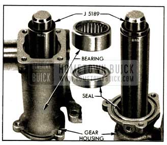
1952 Buick Installing Bearing and Seal in Gear Housing
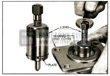
1952 Buick Removing Bearing from End Cover
Use Installer J 5191 to install the new bearing. This tool has a shoulder to locate the bearing at proper depth in cover. See figure 7-28.
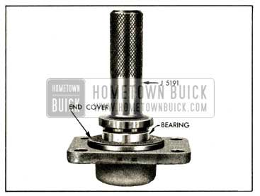
1952 Buick Installing Bearing in End Cover
- Replace pitman shaft seal, installing new seal with feather edge toward inside of gear housing.
- Inspect oil shedder and control shaft bearing in gear housing. If bearing is of doubtful condition replace it.
- Inspect piston rod, teeth and guide bearing surface of power rack, and rack guide for excessive wear or scoring. If necessary to replace piston rod or rack drive out the coupling pin and use new pin to connect new parts. Stake rack at three places on each side to retain the pin, and file down burrs raised by staking.
- Inspect power cylinder bore for scores or other damage. Inspect piston rings for scores or breaks. Inspect seal in power cylinder adapter. If seal is worn or damaged, replace adapter assembly; the seal is not furnished separately for service.
- Inspect valve housing, spool, and centering plungers for scores, nicks, or burred edges. Replace damaged parts and make sure that spool and plungers slide freely in housing.
- Test the check valve by blowing through both ends. Ball should seat when blowing through small end, and allow passage of air when blowing through slotted end of valve body.
- Remove seal from valve cover with a punch and use Installer J 5188 to install a new seal, with the spring side of seal outward toward the shoulder of tool. See figure 7-29.
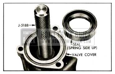
1952 Buick Installing Valve Cover Seal
Assembly of 1952 Buick Power Steering Gear
NOTE: Make sure that all parts are absolutely clean, and lubricate parts with clean engine oil during assembly.
- Place 1952 Buick power steering shaft on bench with upper end to your right, then install ball nut on worm so that when teeth are uppermost the deeper side of teeth are toward you. Install 30 balls in each circuit of the worm, nut, and return guides, and install guide clamp.
- Run ball nut to the upper end of worm, then install steering shaft in gear housing, using care to avoid damaging worm seal in housing. Install end cover with new gasket.
- Install lower thrust bearing over steering worm with the large race outward, and place a new „O“ ring seal in groove in face of gear housing.
- Install check valve in valve housing and tighten securely. Install valve spool. Install centering springs, then install all plungers with narrow lands outward. See figure 7-25.
NOTE: The spool and plungers are a close fit in housing and must be started carefully to avoid jamming. Do not force these parts into place. - Install hose unions with new „O“ ring seals, placing union with smaller outer threads in valve housing port marked “PR” and other union in part marked “RT”. Install elbows and bolts at the other ports with new seals on both sides of each elbow. Do not tighten these parts.
- With steering shaft horizontal, install valve assembly with check valve toward gear housing, using care to keep parts from sliding out of housing. See figure 7-30.
1952 Buick Installing Hydraulic Valve
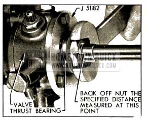
1952 Buick Power Steering Adjusting Worm Thrust Bearings
Stake outer edge of worm bearing nut down into keyway of worm shaft (fig. 7-24), making sure that nut does not turn from its adjusted position.
The thrust bearing adjustment procedure seats the thrust bearings against all centering plungers but leaves approximately .001″ clearance between bearings and spool to avoid the possibility of binding the spool in valve housing.
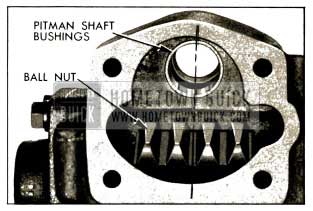
1952 Buick Position of Boll Nut for Installation of Pitman Shaft
Hold pitman shaft with the gear sectors straight down as it is installed in gear housing; use care to avoid damaging pitman shaft seal in gear housing as shaft is pushed through it. Install side cover and tighten bolts securely.
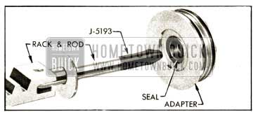
1952 Buick Application of Rod Inserter J 5193
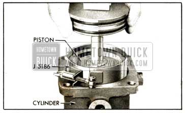
1952 Buick Power Steering Installing Piston With Ring Compresser
1952 Buick Position of Rack and Sector for Installation of Power Cylinder
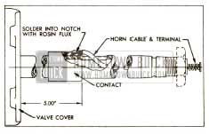
1952 Buick Location of Horn Cable Contact
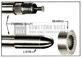
1952 Buick Steering Shaft, Upper Bearing, and Bearing Projector J 51 59
NOTE: It is desirable to fill the valve, tubes, and cylinder as completely as possible to exclude air which would have to be bled out after gear assembly is installed in car. Rapping the value and cylinder with a soft mallet during the filling operation will aid in eliminating air pockets.
7-16 1952 BUICK VICKERS OIL PUMP DISASSEMBLY, INSPECTION, AND ASSEMBLY
Disassembly of 1952 Buick Vickers Pump
- With all inlet and outlet ports plugged and capped to avoid entrance of dirt, thoroughly clean exterior of pump.
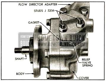
- Remove manifold and two gaskets, using 3/16″ hex (Allen) wrench (fig. 7-38), then remove bolts and separate the cover from pump body.
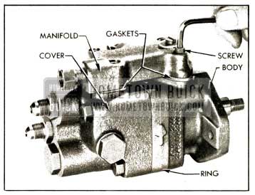
1952 Buick Vickers Pump-Removing Manifold
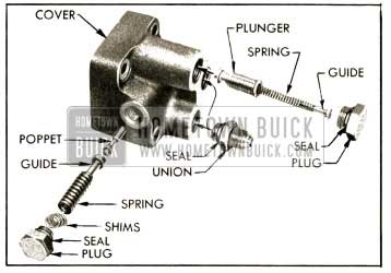
1952 Buick Relief and Flow Control Valve Parts
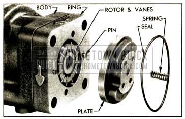
1952 Buick Pressure Plate, Ring, Rotor and Vanes
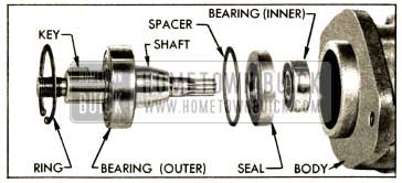
1952 Buick Drive Shaft, Bearings, and Seal
Cleaning and Inspection of 1952 Buick Vickers Pump Parts
- Wipe the bearing and shaft assembly with clean cloths; do not soak in cleaning solvent as the lubricant sealed into the bearing may be diluted by solvent. Wash all other parts in clean kerosene or other solvent and wipe dry with clean lint free cloths.
- Inspect the drive shaft for wear and check both ball bearings for roughness or noisy operation. If the large bearing must be replaced, press the new bearing on shaft with a tool that applies pressure on the inner race only.
- Check fit of vanes in slots of rotor; vanes must slide freely but snugly in slots. Tightness may be relieved by thorough cleaning or removal of irregularities. Replace rotor if excessive looseness exists between rotor and vanes, and replace vanes if they are irregularly worn or scored.
- Inspect all ground surfaces of the ring for roughness or irregular wear. Slight irregularities may be removed with a hard Arkansas stone. Replace ring if inside cam surface is scored or worn.
- Inspect the flat faces of the pressure plate and body for wear or scoring. These faces may be repaired by lapping until smooth and flat, after which all lapping compounds must be thoroughly washed away.
- Inspect ground surfaces of the relief valve poppet and flow control valve plunger, paying particular attention to seating surfaces. Slight irregularities may be corrected by lapping or polishing.
- Inspect all passages in cover and body for obstructions or dirt.
Assembly of 1952 Buick Vickers Pump
Assemble the pump by reversing procedure for disassembly, paying attention to the following items:
- Make sure that all parts are absolutely clean, and lubricate all moving parts with clean engine oil during assembly.
- Use new seals and gaskets.
- Make certain that the bearings and shaft seal are firmly seated in their proper positions. After the inner ball bearing is installed, the shaft seal must be installed with the two 1/16″ holes in casing toward the outside. Use a tube or shaft 1 3/4″ in diameter to apply pressure against outer edge of seal during installation.
- The ring must be installed over the dowel pins with the embossed arrows pointing in a counterclockwise direction as viewed from rear end of pump. See figure 7-40. NOTE: When viewed from the front or shaft end of pump, the arrows on ring point in a clockwise direction, which is the direction of rotation of pump shaft.
- Install vanes in slots of rotor with the rounded edge outward toward the ring.
- Before installing cover make sure that the pressure plate spring is located in the recess in pressure plate. Turn cover bolts down snug only, then install the manifold with gaskets before tightening the cover bolts securely. This is necessary to assure proper alignment of the cover, manifold, and body.
- Install relief valve spring with all original shims and tighten relief valve plug securely. If plug is not firmly seated the relief valve setting will be affected.
- When assembly is completed, rotate pump shaft to make sure of free movement, then plug or cap all hose connections to exclude dirt until pump is installed.
- If any of the relief valve parts were replaced it would be necessary to test pump for relief valve operation after pump is installed on car, as follows:
- Install Gauge J 5176 and check pump pressure as described in paragraph 7-12 (f).
- Relief valve should start to open, as indicated by a slight buzzing noise in pump, at 700 p.s.i. or slightly higher. With engine speed increased above idle, the maximum pump pressure should not exceed 900 p.s.i.
- Change the number of relief valve shims as required to obtain operation specified in (b).
7-17 1952 BUICK EATON OIL PUMP DISASSEMBLY, INSPECTION, AND ASSEMBLY
Disassembly of 1952 Buick Eaton Pump
- With all inlet and outlet ports plugged and capped to avoid entrance of dirt, thoroughly clean exterior of pump.
- Remove large hex cap and seal from the flow director adapter (fig. 7-42) but leave hose connector in place. Remove hose unions and seals from pump cover.
1952 Buick Removing Adapter With Studs J 5206
1952 Buick Relief and Flow Control Valves and Springs
1952 Buick Removing Shaft Bearing Retainer Ring
Cleaning and Inspection of 1952 Buick Eaton Pump Parts
- Wipe the bearing and shaft with clean cloths; do not soak in cleaning solvent as the lubricant sealed into the bearing may be diluted by solvent. Wash all other pump parts in clean kerosene or other solvent and wipe dry with clean lint free cloths.
- Check pump cover and body for wear caused by the rotors. Replace either part if surface is scored or appreciably worn. Replace bearing in cover if worn or noisy.
- Inspect the drive and driven rotors; if noticeably worn or scored replace both parts, which are furnished in matched sets. If these parts appear satisfactory, check the clearance between the rotors at all points with feeler gauges. See figure 7-45. Replace rotors if clearance exceeds .006″.
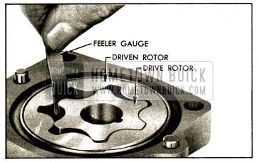
1952 Buick Checking Clearance Between Rotors
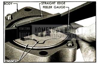
1952 Buick Checking Side Clearance of Rotors in Pump Body
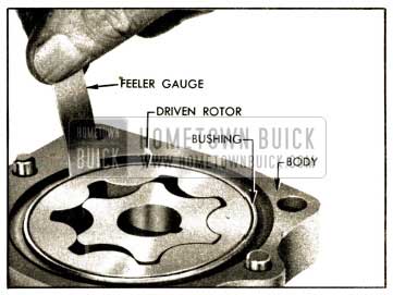
1952 Buick Checking Clearance Between Driven Rotor and Bushing
Assembly of 1952 Buick Eaton Pump
Assemble the pump by reversing procedure for disassembly, paying attention to the following items:
- Make sure that all parts are absolutely clean, and lubricate all moving parts with clean engine oil during assembly.
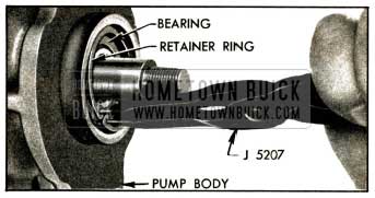
- Install shaft and bearing as an assembly, and press against outer race to seat bearing in body. See figure 7-48.
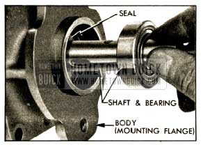
1952 Buick Installing Shaft and Bearing
Leave A Comment
You must be logged in to post a comment.