SECTION 13-D 1952 BUICK DOOR AND REAR QUARTER WINDOWS AND VENTILATORS
13-14 1952 BUICK DOOR AND REAR QUARTER WINDOWS-CLOSED BODIES
NOTE: See paragraph 13-15 for Riviera and paragraph 13-16 for Convertible body windows.
Description of 1952 Buick Windows
Each 1952 Buick door and rear quarter window has a safety plate glass which slides vertically in felt glass run channels. The lower edge of door and rear quarter window glass is sealed into a metal sash channel. A channel-shaped cam or track attached to the sash channel is engaged by knobs on the main and idler arms of the window regulator assembly mounted on door or rear quarter inner panel. A knob on the opposite end of regulator idler arm slides in a channel-shaped regulator cam or track mounted on inner panel.- The cams cause the arms of window regulator to apply evenly distributed pressure on lower sash channel to raise or lower the glass without tilting and binding in glass run channels.
Style “69” (M /41) rear doors have small stationary windows mounted in rubber weatherstrips, located to rear of the vertically opening door windows. Style “69D” (M/41D) rear doors have friction type ventilators at this location.
Replacement of 1952 Buick Series 40 Door Window Glass Run Channel
Series 40 door window glass run channels are made in one section, and are attached by clips to the pinchweld flange of window opening and anchored to the 1952 Buick door pillar by screws.
- Remove garnish molding and door trim pad (par. 13-19) and remove the large inspection hole cover from door inner panel.
- With glass in raised position, loosen the screw securing the lower end of channel to the door pillar, working through the inspection hole.
- Lower the window glass and release the channel clips along the door header and pillar, then pull channel up through window opening and remove.
- To install glass run channel reverse the removal procedure. Align lower end of channel for free travel of window glass. Seal the inspection hole cover before 1952 Buick door trim pad is installed (par. 13-19).
Replacement of Series 50-70 Door Window Glass Run Channel
Series 50-70 door window glass run channels are made in two sections, upper and lower.
- To remove the upper section only of glass run channel, remove garnish molding and pry clips of channel from pinchweld flange of window opening.
- To also remove the lower section of channel, remove 1952 Buick door trim pad (par. 13-19) and the inspection hole cover adjacent to lower end of channel. Through inspection hole remove screw that retains lower end of channel to door pillar, then pull channel up through window opening.
- To install glass run channel sections reverse the removal procedure, making sure that sections are aligned to permit free travel of window glass. Seal the inspection hole cover before 1952 Buick door trim pad is installed (par. 13-19).
Replacement of Window Division Channel
NOTE: On 1952 Buick Series 40 front and rear doors the division channel is integral with the door ventilator assembly and can only be replaced with the assembly as described in paragraph 13-17. On rear doors having small stationary window the division channel is a separate piece that can be replaced as described below.
- Remove 1952 Buick door trim pad (par. 13-19) and release the clips in the glass run channel adjacent to the window division channel and drop it down out of position.
- Remove the retaining screw holding upper end of division channel to door header and remove the two self-tapping screws attaching division channel to the top edge of door inner panel. See figure 13-28.
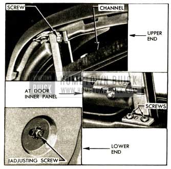
1952 Buick Window Division Channel Attachments
- Remove inspection hole cover from door inner panel adjacent to lower end of division channel.
- Remove nut and adjusting screw at the bottom of division channel, noting before removal the length of the screw projecting out from inner panel. This will aid proper adjustment when installing channel.
- With ventilator open (front door) or window glass down (rear door) swing division channel out of position, pull up and remove through the window opening of 1952 Buick door.
- When division channel is installed by reversing procedure for removal, adjust the screw at lower end of channel to same length as it was before removal. Operate the door window and the ventilator to see whether the division channel is properly positioned for smooth operation of window glass and full closing of ventilator.
If channel is not properly positioned, adjust the lower end in or out, forward or rearward at the screw as required to obtain free movement of window glass.
Replacement of 1952 Buick Door Window Glass
- Remove 1952 Buick door trim pad (par. 13-19) and remove inspection hole covers or tape to provide access to lower sash channel screws. Remove garnish molding retaining clips from door inner panel, if present.
- On all Series 40 doors except Style “69” (M /41) rear doors, remove ventilator and division channel assembly (par. 13-17). On Style “69” rear door remove window division channel (subpar. d, above).
On Series 50-70, remove glass run channel and window division channel (subpar. c and d; above).
- With glass in lowered position, remove screws attaching the cam to lower sash channel. See figure 13-29.
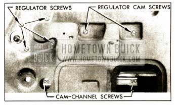
1952 Buick Window Regulator and Cam Attaching Screws
- Carefully raise the glass to an almost closed position and tilt inward using care to work out one lower corner at a time to avoid damage.
- Install glass by reversing removal procedure. Before sealing door inner panel and installing trim pad (par. 13-19) raise and lower the window glass several times to check for smooth operation.
If glass binds or has excessive edgewise play it may be necessary to adjust the window division channel at lower end.
If glass tilts edgewise, adjust the regulator cam (fig. 13-29) at rear end where the attaching screw hole is slotted vertically. Raise rear end of cam to throw travel of glass forward or lower rear end to throw travel of glass rearward.
Replacement of 1952 Buick Door Window Regulator
- Remove trim pad (par. 13-19) and inspection hole cover to provide access to lower sash channel screws.
- On Series 40 front door only, remove door window glass (subpar. e above). On all other doors remove screws attaching the cam to lower sash channel (fig. 13-29) then raise glass to closed position and support it there.
- Slide the sash channel cam off the ends of regulator arms.
- Remove four screws attaching window regulator, and two screws attaching regulator cam to door inner panel. Remove regulator and cam through inspection hole, using care to avoid scratching window glass.
- To install regulator and cam, set regulator in place, install cam over knob on idler arm and install regulator and cam attaching screws. The hole in inner panel for cam screw nearest lock pillar is slotted vertically. Set the screw at top of slot when tightening it.
- After installation of lower sash channel cam, raise and lower window glass several times to check for smooth operation of glass in run channels. If glass binds or has excessive edgewise play it will be necessary to adjust the window division channel at lower end. If glass tilts edgewise, adjust the regulator cam at slotted screw hole as required.
- Seal and install inspection hole cover, install covering over small hole in panel, and install trim pad, (par. 13-19).
Replacement of Rear Door Stationary Window
On Series 40 Style “69” bodies, the rear doors have small stationary windows in place of ventilators.
- Remove 1952 Buick door trim pad (par. 13-19) and window division channel.
- Slide entire glass and rubber channel assembly toward center pillar to clear the metal retaining tabs, then exert pressure on assembly toward inside of door and remove the assembly.
- Remove glass from rubber channel if required.
- Revere the removal procedure to install the parts. During installation of glass and channel pull outer lip of rubber channel up over door outer panel.
Replacement of Series 40 Rear Quarter Window Glass Run Channel
- Remove rear quarter window garnish molding, then remove the screw from channel tab at rear of window opening.
- Disengage channel clips from window opening by pulling channel toward inside of body at clip locations, then remove channel by pulling up to slide channel out of retainer at each lower end.
The front channel retainer remains anchored with a single screw. The rear retainer is held by a slide-on clip which may pull free with the channel.
- To install channel, reverse the removal procedure. If rear retainer has pulled free from its retaining clip, install it on end of glass run channel and then insert it in clip.
Use care when installing channel to avoid damaging the headlining with the clips.
Replacement of 1952 Buick Series 40 Rear Quarter Window Glass
- Remove rear seat cushion and back, arm rest, window regulator handle, garnish molding and retainers.
- Raise window glass, then loosen the quarter trim panel sufficiently to expose openings in inner panel which provide access to the lower sash channel screws.
- Remove the four screws securing the window lower sash channel to the cam. See figure 13-30.
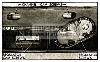
1952 Buick Rear Quarter Window Regulator and Cam Attaching Screws
- Disengage sash channel from cam and lower the cam as far as possible by turning the regulator handle.
- From inside of body, grasp top edge of glass and lower the rear corner of glass to clear the glass run channel, then lift glass up and tilt inward to remove it.
- To install glass reverse the removal procedure. The stationary cam attaching screws (figure 13-30) pass through vertically slotted holes in the rear quarter inner panel to permit adjustment or alignment of the glass in window opening.
Replacement of 1952 Buick Series 40 Rear Quarter Window Regulator
- Remove 1952 Buick rear quarter trim panel and remove rear quarter window glass (subpar. i, above).
- Operate regulator arms into window opening and slide .the sash channel cam off the arms.
- Lower the regulator arms to a point approximately in line with the stationary regulator cam, remove tape covering the cam, then remove cam which is attached by two screws. See figure 13-30.
- To install regulator, reverse the removal procedure. Before installing rear quarter trim panel, apply 3-M Autobody Sealer over entire perimeter of regulator cover plate and over heads of attaching screws. Apply a heavy ribbon of sealer along lower ledge of regulator cam depression in panel, then cover the depression with body tape.
13-15 1952 BUICK DOOR WINDOWS – RIVIERA AND CONVERTIBLE BODIES
Description of 1952 Buick Windows
Each Riviera and Convertible door window glass is protected by metal channels sealed to the top and rear edges. The bottom edge of glass is sealed into a metal sash channel which is connected to the regulator which raises and lowers the glass vertically.
The forward edge of window glass slides in a glass run channel incorporated in the 1952 Buick door ventilator assembly. Except in Model 46C, a window guide is located near the lock pillar to support the rear edge of window when in raised position. The glass run channels on door ventilator and lock pillar are adjustable to provide proper alignment of door window with adjacent parts.
In closed position, the rear edge of 1952 Buick door window bears against a weatherstrip mounted on the rear quarter window frame. On Model 45R and all Convertibles, the upper edge of window bears against a weatherstrip mounted on the roof side rail.
On Models 56R and 76R, the top edge of window is sealed, in closed position, by a mechanical or “flipper” type roof side rail sealing strip. When the door is opened, tension springs “flip” a hinged sealing strip upward to permit the door window to pass underneath. As the door is closed, the top of door ventilator frame bears against a striker in the assembly which causes the hinged sealing strip to swing down against the outer side of door ventilator frame and window glass channel, and the tension springs press the sealing strip firmly against these parts. A rubber gasket placed between the sealing strip assembly and roof side rail has a lip which covers the hinged section of the assembly. See figure 13-31.
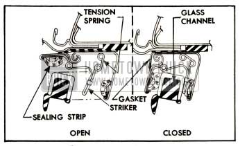
1952 Buick Roof Side Rail Sealing Strip Operation
On Models 45R and 56R, the door window is operated by a mechanical type regulator with handle on inside of door. On Model 76R and all Convertible bodies, the door window is operated by the Hydro-Lectric Power System described in Section 13-G.
Adjustment of Roof Side Rail Weatherstrip-Convertible and Model 4 5R Bodies
The roof side rail weatherstrip adjustment on Convertible and Model 45R bodies is basically the same, except that the Convertible weatherstrip consists of three sections which are adjustable over the door and rear quarter windows, whereas the Model 45R weatherstrip is adjustable over the door window only.
- Open the door and lower the rear quarter window. On Convertible body, partially lower the folding top.
- Carefully remove the roof side rail weatherstrip from its metal retainer mounted on the side rail. On Model 45R, it is necessary to remove a screw at each end of weatherstrip.
- For a lateral (in or out) adjustment, loosen the retainer attaching screws just enough to permit movement of the retainer and gasket as required, then tighten screws securely. On a Convertible side rail the retainer screw nuts are located in the channel on upper side of rail.
- If a downward adjustment of weatherstrip is required, loosen retainer screws and insert waterproof shims between the retainer and side rail as required, then tighten screws.
- Install weatherstrip in retainer and check alignment with window and ventilator frame.
- Work a bead of 3-M Caulking Compound into the outside joint between the weatherstrip retainer gasket, and roof side rail. On Model 45R, also apply 3-M Weatherstrip Adhesive to the joints at both ends of weatherstrip.
Adjustment of Mechanical Type Roof Side Rail Sealing Strip
The attaching screw holes in the mechanical sealing strip are slotted laterally to allow in and out adjustment for alignment with the top of door window and door ventilator. To adjust, simply loosen attaching screws, move sealing strip in or out as required, and tighten screws securely.
If the hinged “flipper” strip has a tendency to bind or operate slowly, loosen attaching screws one at a time until the screw causing the bind is located. Prepare a slotted shim of waterproof cardboard and insert it between the upper gasket and the roof side rail so that it straddles the screw which causes the bind. It may be necessary to install shims at several screws in order to obtain proper operation of sealing strip. See figure 13-32.
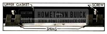
1952 Buick Sealing Strip Shims
Do not hammer the sealing strip, pry on it with a screw driver, or tamper with the spring mechanism. Such abuse will damage the mechanism and render it inoperative.
Replacement of Mechanical Type Roof Side Rail Sealing Strip
- Remove the retainer and corner sealing strip which are attached by one screw at front end of the roof side rail sealing strip.
- Remove attaching screws, then remove the sealing strip with the cemented upper and lower side rail gaskets.
- Remove gaskets from sealing strip and clean off all old adhesive from all surfaces of these parts; also clean off old adhesive from underside of roof side rail.
- Tape the hinged, “flipper” strip down in the closed position. See figure 13-33. Apply a light uniform coating of 3-M Weatherstrip Adhesive to the top surface of sealing strip assembly, being careful to keep adhesive out of the screw holes and hinge section.
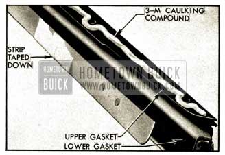
1952 Buick Sealing Strip and Gaskets
- Apply a light coating of 3-M Weatherstrip Adhesive to the bottom surface of the side rail lower gasket, except on the outer lip.
- When the adhesive coatings have become “tacky” carefully apply the gasket to the top surface of sealing strip so that the lip of gasket is precisely located over the outside radius of the hinge throughout its entire length. The gasket must be cemented flat without any wrinkles or high spots.
- Use 3-M Weatherstrip Adhesive to cement the side rail upper gasket to the top surface of lower gasket.
- Apply a uniform continuous 1/8″ ribbon of 3-M Caulking Compound along the centerline and around outer edges of screw holes on top surface of upper gasket. See figure 13-33.
- Carefully install the sealing strip and gaskets on underside of roof side rail. Before tightening the screws, make sure that the channel of sealing strip aligns properly with top of door window and ventilator.
- If the hinged “flipper” strip binds or operates slowly after screws are tightened, check for cause of bind and install shims as described in subparagraph c. above.
- Cement and install the small front corner rubber sealing strip and install the retainer with screw. At rear end of sealing strip, cement the small rubber weatherstrip to the end of rear quarter window upper sash channel.
Adjustment of 1952 Buick Door Window Glass
- Remove door trim pad (par. 13-19).
- To adjust upward limit of travel of window glass for alignment with roof side rail weatherstrip and top of ventilator division channel, adjust the stop screws located on upper edge of door inner panel. See figure 13-34.
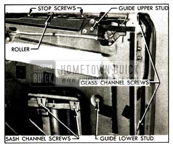
1952 Buick Door Window Adjustments
- To adjust downward limit of travel of mechanically operated window glass for alignment with top edge of door, trim the rubber window stop or bend the supporting bracket.
To make this adjustment on a hydraulically operated window glass, loosen the sash channel screw nuts (fig. 13-34) and move window glass on regulator as required, then tighten nuts.
- To adjust window glass laterally (in or out) for proper vertical line of travel, raise the glass and loosen the glass channel screws in lock pillar face of door. See figure 13-34.
On Model 46C adjust glass channel as required; the lower screw hole is slotted to permit lateral adjustment. Tighten screws.
On Model 45R and Series 50-70, adjust the upper and lower window guide studs as required, then tighten glass channel screws.
On all jobs, make a corresponding adjustment on the window division channel lower adjusting stud so that glass will not bind, and check glass operation for free movement.
- If glass is tilted so that upper corner does not align with window division channel, loosen the upper and lower window guide stud nuts, if present. On mechanically operated window glass, loosen the regulator cam screws and adjust glass for proper alignment. On hydraulically operated glass, loosen the sash channel screw nuts and move glass on regulator as required. Tighten all screws and nuts securely.
- In some cases it may be necessary to adjust the door ventilator assembly (par. 13-17) or the rear quarter window (par. 13-16) to obtain satisfactory alignment of door window glass with these adjacent parts.
- After all adjustments are completed, perform the specified sealing operations and install door trim pad (par. 13-19).
Replacement of 1952 Buick Door Window Glass
- Lower the door window glass to full “down” position and remove the door trim pad (par. 13-19). Disconnect wire leads from hydraulic lift switch after trim pad has been freed from its retainers, and tape ends of wires to prevent accidental operation of lift mechanism.
- Clean off sealing compound and remove hydraulic lift bracket screw from the large inspection hole cover, then remove the cover.
- Remove the inner draft strip bracket including glass stop screws, which is attached by screws to upper edge of door inner panel.
- On manually operated window, remove the screws attaching the cam to the lower sash channel at lower edge of window glass.
On hydraulically operated window, loosen the two bolts which attach the lower sash channel forks to the window lift cam, then raise the glass sufficiently so forks will clear the cam.
- Lower the window glass far enough to remove the narrow draft strip attached to the flange along top edge of door outer panel.
- Remove glass and sash channel assembly from door by raising and tilting it inward at the top so that top front edge of glass will clear the lip of door ventilator frame.
In this operation it may be necessary to apply a little powdered graphite along inner edge of door outer panel to eliminate binding of the window rubber water deflection.
- Install window glass by reversing removal procedure. Reseal inspection hole cover and hydraulic lift bracket screw with 3-M Autobody Sealer before installing door trim pad (par. 13-19).
13-16 1952 BUICK REAR QUARTER WINDOWSRIVIERA AND CONVERTIBLE BODIES
Description of 1952 Buick Windows
Each rear quarter window glass is sealed into a channel which protects the front and lower edges and supports the glass in body opening. The upper edge is protected by a separate channel. The front lower corner of glass and channel assembly is pivoted on a bolt in an adjustable hinge mounted on the rear quarter inner panel. A circular track or guide mounted in rear quarter between the inner and outer panels steadies the rear end of the assembly as the window is opened and closed with a swinging motion.
A channel shaped cam mounted on the lower glass channel is engaged by the window regulator. On models equipped with the Hydro-Lectric Power System, the window is operated by a hydraulic window regulator, described in Section 13-G. On other models the window is operated by a manual type regulator similar to the regulator used on doors.
Adjustment of 1952 Buick Rear Quarter Window
- Remove rear quarter trim panel far enough to provide access to the pivot bolt and adjusting studs at front upper corner of rear quarter inner panel.
- Loosen the pivot bolt and two adjusting stud lock nuts. See figure 13-35.
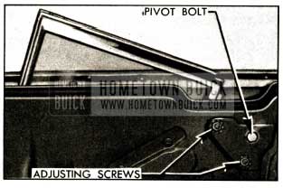
1952 Buick Rear Quarter Window Adjustments
- Up and down adjustment is made by shifting the window as required and then tightening pivot bolt and stud lock nuts.
- Lateral or in and out adjustment is made by turning the adjusting studs with screw driver. Turning studs clockwise will move the top of the window glass inward.
- After adjustment, tighten adjusting screw lock nuts securely. Tighten pivot bolt firmly enough to prevent looseness of window but not so tight that window is hard to operate.
- Operate window from fully opened to closed positions to check for any binding on window guide or contact with other parts in window well, which would require adjustment of the window guide.
- If window guide adjustment is required, remove trim far enough to uncover the guide adjusting screw in rear quarter inner panel between the inspection holes, and also to uncover the guide lower end attaching screws. On Series 40, the lower end attaching screw is on front face of body lock pillar.
- The lower end of window guide may be adjusted laterally by loosening the attaching screws which run through slotted holes. The center of guide may be adjusted laterally by loosening lock nut and turning the adjusting screw with screwdriver.
- If window glass closed position is incorrect, the glass stop at rear lower corner of window opening may be adjusted by loosening the screws attaching the upper glass run guide and stop to the rear quarter inner panel, and moving the glass stop up or down as required.
- Except on Mod el45R, the glass is stopped in the lowered position by a rubber bumper at front lower end of window guide. On Model 45R the window glass channel has an adjustable stop mounted on the lower rear end. This stop may be adjusted through the small inspection hole in the quarter inner panel.
- If the weatherstrip on front edge of window is removed for any reason, use 3-M Weatherstrip Adhesive to cement the upper six inches of weatherstrip to the frame during installation.
Replacement of 1952 Buick Rear Quarter Window
- On Riviera body, lower the rear quarter window to an almost down position. On Convertible body, lower the window to full down position and also lower the folding top.
- Remove rear seat cushion and back, and inside hardware and arm rest from rear quarter.
- Disengage rear quarter trim pad from its rear attachment and swing it forward. During this operation disconnect wiring harness from its retaining clip on inner panel if window is hydraulic type. The hydraulic lift switch need not be removed from trim pad.
- Remove the quarter window pivot bolt located in upper front corner of rear quarter inner panel. See figure 13-35.
- On Riviera body, remove the large inspection hole cover from inner panel. Carefully disengage cam from the glass sash channel, raise window, and remove it through the window opening.
On Convertible body, slowly raise the window and at the same time carefully pull it forward to release the cam from the sash channel, then remove window through the window opening.
- Install rear quarter window by reversing the removal procedure. Refer to subparagraph b. for window adjustments. Seal all screws on inner panel with 3-M Caulking Compound. Seal inspection hole cover with 3-M Autobody Sealer.
13-17 1952 BUICK DOOR AND REAR QUARTER VENTILATORS-ALL BODIES
Description of 1952 Buick Ventilators
Each ventilator has a safety plate glass sealed into a metal channel which is mounted to pivot vertically. In closed position the ventilator bears against molded rubber weatherstrips which seal all edges.
Front door ventilators are similar on all models except that on Riviera and Convertible models the ventilator is supported by a frame which is mounted on the door in such manner that the entire ventilator assembly may be adjusted to obtain proper alignment with the body pillar, door window, and roof side rail. These ventilators are manually operated by a regulator mounted on door inner panel. A sliding bolt on the glass channel provides a safety lock for the ventilator when closed.
Rear door and rear quarter ventilators used on some models have a friction mechanism to hold the ventilator in the desired position. The friction mechanism is a part of the ventilator frame and consists of a heavy coil spring mounted on the frame spindle to exert frictional force against the mounting support. The inside handle of these ventilators provide a lock for the closed position.
Replacement of 1952 Buick Ventilator Regulator
- Remove door trim pad (par. 13-19) and remove inspection hole cover located below ventilator.
- Remove clamp screw which attaches glass channel T-shaft to regulator, also the regulator attaching screws. See figure 13-36.
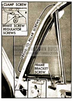
1952 Buick Closed Body Front Ventilator and Regulator Mountings
- Remove regulator through inspection hole in 1952 Buick door inner panel.
- Install regulator by reversing the removal procedure. Before installing regulator apply a 3/16″ head ov 3-M Caulking Compound around upper and side edges where regulator contacts door inner panel, also seal the clearance hole in panel just above the regulator handle shaft.
Adjust the brake screw (fig. 13-36) to provide proper operating tension on regulator before installing door trim pad.
Replacement of Closed Body Front Door Ventilator
- Remove 1952 Buick door trim pad and the ventilator regulator (subpar. b., above).
- Lower the window glass and release the glass run channel along door header adjacent to window division channel.
- On Series 50-70, remove the window division channel (par. 13-14, d). On Series 40, remove the division channel lower adjusting stud nut and washer. The Series 40 division channel is integral with the ventilator assembly and cannot be removed separately.
- Remove screws attaching ventilator frame bracket to door inner panel. See figure 13-36.
- Remove screws attaching ventilator frame to door hinge pillar. On Series 40, these screws are concealed behind inside lip of ventilator weatherstrip; on Series 50-70, screws are on outer face of door hinge pillar.
- Carefully loosen weatherstrip where cemented to window reveal, then remove the ventilator assembly.
- When ventilator assembly is installed by reversing removal procedure, apply 3-M Autobody Sealer between contacting surfaces of ventilator frame attaching brackets and door inner panel. Seal between lip of weatherstrip and the reveal moldings.
- Before installation of trim pad (par. 13-19) operate the door window and the ventilator to see whether the division channel is properly adjusted. The lower end of channel may be adjusted forward, rearward, in, or out at the adjusting stud at lower end.
Adjustment of Riviera and Convertible Door Ventilator
The following adjustments may be used to improve the fit of ventilator glass in the frame and to improve the weather sealing between the ventilator assembly and body. When adjusting the ventilator it may also be necessary to adjust the door window glass (par. 13-15, e).
- Remove door trim pad (par. 13-19).
- To move the upper end of ventilator assembly inward or outward, loosen the frame adjusting screw lock nut and turn adjusting screw with screw driver. Turning adjusting screw clockwise moves ventilator frame inward. It may be necessary to loosen the upper ventilator screws slightly. See figure 13-37. Tighten screws and lock nut securely when adjustment is completed.
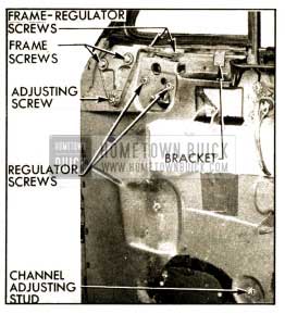
1952 Buick Ventilator Adjustments-Series 50-70 Shown
- To move ventilator assembly up, down, forward, or rearward – loosen frame screws, adjusting screw lock nut, regulator screws, channel adjusting stud lock nut, then remove the frame bracket screw and the division channel screw at upper edge of inner panel. See figure 13-37. Move ventilator in required direction then tighten all screws and lock nuts. It may be necessary to relocate the holes for the frame bracket and division channel screws to reinstall them.
- To raise or lower the ventilator glass in the frame, loosen the clamp screw which attaches glass channel T-shaft to ventilator regulator, shift glass, then tighten clamp screw. In extreme cases it may be necessary to loosen the regulator screws and place shims between the regulator and the bracket of frame at the connecting screws.
- To move ventilator glass forward or rearward loosen the regulator screws, carefully pry forward or rearward against ventilator shaft, then tighten regulator screws securely.
- If the bottom of ventilator glass will not close against the division channel, loosen the regulator screws and place a washer over the forward screw between door inner panel and regulator. Tighten rear screw first, then the front screw.
- After completing all ventilator adjustments install door trim pad (par. 13-19) and carefully inspect the sealing of rubber weatherstrip along the lower edge and front end of ventilator assembly. Use 3-M Weatherstrip Adhesive to securely seal this weatherstrip.
Replacement of Riviera and Convertible Door Ventilator Assembly
- Remove door trim pad (par. 13-19).
- With a razor blade, carefully cut the ventilator and door rubber weatherstrip at the front end of belt molding.
- Clean sealer from division channel lower adjusting stud and remove stud. See figure 13-37.
- Remove screws attaching the division channel and the ventilator support bracket to door inner panel.
- Remove clamp screw that attaches ventilator shaft to ventilator regulator and remove two screws attaching ventilator frame bracket to the regulator.
- Remove ventilator frame attaching screws and adjusting screw.
- Carefully loosen weatherstrip seal and remove ventilator assembly, including attached division channel.
- Install ventilator assembly by reversing removal procedure. Cement together the butt ends of the door rubber weatherstrip where previously cut, and also cement the ventilator weatherstrip to belt molding, using 3-M Weatherstrip Adhesive.
- After adjusting the ventilator assembly for alignment with body and window glass (subpar. d., above) apply a seal of 3-M Caulking Compound over the division channel adjusting stud before installing door trim pad (par. 13-19).
Replacement of Rear Door Ventilator – Model 41D
The friction type ventilator used on Model 41D rear doors has the window division channel as an integral part of the assembly.
- Remove door trim pad (par. 13-19) and remove the rear inspection hole cover.
- Remove window division channel lower adjusting stud.
- Remove four screws that attach the ventilator frame to door header. These screws are concealed by the inside lip of ventilator weatherstrip.
- Remove four screws that attach ventilator lower support brackets to door inner panel.
- Lower the window glass and release the glass run channel from door header near division channel.
- Remove ventilator assembly by working it out of opening and pulling upward to extract lower end of division channel.
- Install ventilator by reversing removal procedure. Adjust division channel lower stud for proper alignment of ventilator and door window before installing door trim pad (par. 13-19).
Replacement of Rear Quarter Ventilator
- Remove ventilator garnish molding, loosen rear quarter trim panel at upper rear corner and swing it forward.
- Loosen headlining and boarded trim panel over ventilator sufficiently to gain access to the ventilator upper support screws.
- Remove four screws attaching ventilator to roof side rail and remove three screws attaching ventilator to rear quarter inner panel. See figure 13-38. Remove ventilator assembly from body.
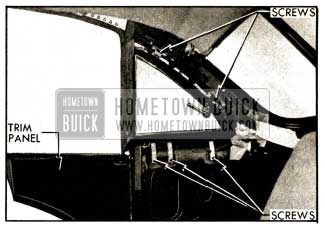
1952 Buick Rear Quarter Ventilator Installation
- Install ventilator by reversing removal procedure. Clean off old sealer from ventilator opening and lip of rubber weatherstrip. Apply 3-M Weatherstrip Adhesive under outer lip of weatherstrip completely around the opening.
13-18 1952 BUICK DOOR AND WINDOW MOLDINGS
Replacement of Garnish and Inside Belt Finishing Moldings
- On models where the ventilator regulator handle is located over the molding to be removed, remove handle by pushing inward on the escutcheon and removing the handle retaining spring, using Door Handle Pliers KM0-601. See figure 13-44.
- Unscrew knob from inside safety locking rod and remove all garnish molding screws. On closed body door, pull top portion of molding out slightly and lift upward to disengage lower side from retainers on door.
- If a belt finishing molding is used, remove all retaining screws from both ends and lift molding up to free it from retaining clips on door.
- Install moldings by reversing removal procedure. Apply 3-M Weatherstrip Adhesive to threads of locking rod before installing the knob.
Replacement of Door Belt Molding – Series 40 Closed Bodies
- Protect door panel on each side of belt molding with masking tape.
- Insert putty knife or similar tool beneath lower edge of molding and carefully snap the lower edge from retaining clips and remove molding.
- Before installation of belt molding check all retaining clips for damage and replace if necessary. Apply 3-M Autobody Sealer around the clip attaching hole before pressing clip into place on door panel. See figure 13-39. On front doors apply Sealer over the forward two retaining clips to effect a watch-tight seal.
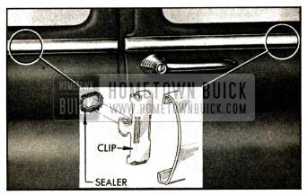
1952 Buick Belt Molding Installation-Series 40 Closed Body
- Align molding fore and aft on door and engage upper edge of molding over all clips; then snap lower edge over clips by using a contoured padded block or the heel of hand.
Replacement of Door Belt Molding – Models 45R, 46C
- Remove door trim pad (par. 13-19) and rear inspection hole cover.
- Remove door ventilator (par. 13-17, e.).
- Lower the door window glass, disconnect sash channel from cam, then lower the window glass to expose the belt molding attaching screws along inner flange of door outer panel.
- Remove attaching screws and pull belt molding up to disengage the retaining clips from slots in door outer panel.
- Install molding by reversing this procedure.
Replacement of Door Lower Reveal and Belt Moldings-Series 50-70
- Remove door trim pad (par. 13-19) and inspection hole cover from door inner panel.
- Remove the four screws attaching cam to lower sash channel (fig. 13-29) and lower the window glass below sill of window opening.
- On front door only, remove door ventilator (par. 13-17).
- Remove rivet attaching rear end of reveal molding to door flange, if present.
- Remove screws attaching molding to retainers on door, then lift molding up to remove it. See figure 13-40.
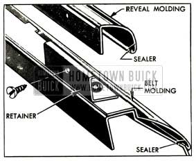
1952 Buick Door Lower Reveal and Belt Molding Attachments
- To remove belt molding also, remove screws and reveal molding retainers along lower edge of window opening, then remove belt molding. See figure 13-40.
- Before installation of moldings, apply 3-M Autobody Sealer along inside of the outer curled edges of both moldings and to all retainer screw holes, then install moldings by reversing the removal procedure.
Replacement of Rear Quarter Belt Moldings
In most cases, the rear quarter belt molding is a continuation of the rear end belt molding; replacement is covered in paragraph 13-11 (e). Models 45R and 46C use a separate rear quarter belt molding which overlaps the front end of the rear belt molding. It is replaced as follows.
- Remove rear quarter window (par. 13-16, c.).
- Remove screws attaching quarter belt molding to inner flange of rear quarter outer panel, then gently pull molding up to disengage the retaining clips from slots in quarter outer panel.
- Install molding by reversing this procedure.
Replacement of Rear Quarter Window Sash Channel and Reveal Molding
- Lower the rear quarter window and remove attaching screws from groove of sash channel “B” and screws “A” attaching lower end of sash channel and end of quarter window guide assembly to the body. See figure 13-41.
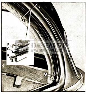
1952 Buick Rear Quarter Window Seal- Channel and Reveal Molding
- Break seal between gasket “C” and sash channel and remove channel.
- Remove gasket from reveal molding “D” and clean sealer from reveal molding. Remove screws retaining reveal molding to side roof rail and rear draft strip.
- Break seal along the entire length of the reveal molding. Then, carefully pull front of molding away from the body, rotate the molding slightly to clear belt molding and remove.
- Apply a wide bead of 3-M Weatherstrip Adhesive to the reveal channel in the side roof rail. Install the reveal molding.
- Apply a wide bead of 3-M Weatherstrip Adhesive to the lower side of the reveal molding and install gasket. Apply another seal of 3-M Weatherstrip Adhesive to the lower surface of the gasket.
- Install lower end of sash channel behind the upper end of the guide channel and install retaining screw.
- Install remaining screws in inside of sash channel loosely. Raise quarter window slowly to align the sash channel, then lower the window and tighten screws.
Replacement of Rear Quarter Ventilator Header Molding-Style “19”
- Remove rear quarter belt molding (par. 13-11, e.).
- Above rear quarter ventilator at “B,” inside the body, remove the two barrel nuts and washers securing the header molding. See figure 13-42.
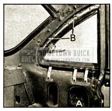
1952 Buick Rear Quarter Ventilator Inside Area
- Remove the single screw holding end flange of header molding to body lock pillar, then remove the two screws holding lower end of molding to rear quarter panel.
- Before installing header molding, apply continuous heads of 3-M Autobody Sealer to metal flanges of rear quarter pillar from lower corners upward as indicated at “A” in figure 13-43. Circle each screw hole with sealer as indicated at “B.”
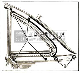
1952 Buick Sealing of Ventilator Header Molding
- Install header molding by reversing procedure for removal.
Replacement of Door and Rear Quarter Side Moldings
Door and rear quarter side moldings on all models are attached by bolt type retainers, with flat washers and nuts on inside of door or rear quarter outer panel. These moldings must not be pried off. To replace a molding, remove door or rear quarter trim and inspection hole covers on the inner panel to provide access to the retainer nuts.
Leave A Comment
You must be logged in to post a comment.