SECTION 13-G 1952 BUICK HYDRO-LECTRIC POWER SYSTEM
13-24 GENERAL DESCRIPTION OF 1952 BUICK HYDRO-LECTRIC POWER SYSTEM
The 1952 Buick Hydro-Lectric Power System is standard on Models 46C, 56C, 76C and 76R, and is optional equipment on Models 52 and 72R. This system provides power operation of the 1952 Buick folding top, 1952 Buick front seat, 1952 Buick door and rear quarter windows.
The 1952 Buick Hydro-Lectric Power System is a combination hydraulic and electric system in which hydraulic fluid pressure, generated by an electrically driven pump (the power unit) is piped to hydraulic cylinders which apply the fluid pressure in raising and lowering the top, raising windows, and moving the front seat forward, depending upon the controls being operated. Spring pressure is used to lower the windows and move the seat rearward.
Steel tubing is used for the pipes which conduct the hydraulic fluid between the power unit pump and the hydraulic cylinders which operate the folding top, windows and front seat. Rubber hoses are used at the power unit and where the lines enter the doors at hinge pillars, to provide the flexibility required at these points. The fluid pipes are formed in loops at the lower ends of folding top power cylinders to provide flexibility required by the slight hinging movement of these cylinders during operation.
One pressure line runs from the power unit pump to the door window hydraulic cylinders and this line serves to return fluid from the cylinders to pump reservoir. Another pressure line runs from the pump to the seat adjuster, folding top control valve and cylinders, and rear quarter window hydraulic cylinders. This line also serves to return fluid from seat adjuster and quarter window cylinders to pump reservoir. A separate return line is provided for the folding top hydraulic cylinders.
The car battery supplies the current used by the power unit motor. This current is controlled by a solenoid relay switch mounted on the motor. The solenoid relay switch, in turn, is controlled by the folding top, window and seat control switches located at convenient points in the body.
The ignition switch must be turned “ON” in order to operate any part of the 1952 Buick Hydro-Lectric Power System since all controlling circuits pass through this switch. The controlling circuits also pass through a circuit breaker, mounted on dash under the cowl, which protects the circuit wiring and electrical units. Current used by the power unit motor does not pass through the ignition switch and circuit breaker.
The circuit wiring diagrams for bodies having the 1952 Buick Hydro-Lectric Power System are shown in figures 10-120, 10-121 and 10-122.
13-25 1952 BUICK HYDRO-LECTRIC POWER UNIT ASSEMBLY
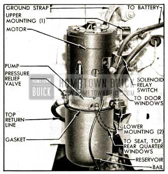
The power unit assembly provides hydraulic fluid pressure when required for operation of the folding top, windows and front seat. It is mounted on the right side of cowl under the rear end of front fender and may be reached by raising the hood. The assembly is cushioned on rubber mountings, is connected to the hydraulic fluid pipes by rubber hoses, and the motor is electrically grounded to the body by a flexible ground strap. See figure 13-57.
1952 Buick Hydro-Lectric Power Unit Installation
The power unit assembly consists of an electric motor, a rotor type oil pump, and a fluid reservoir assembled vertically into a single unit. A solenoid relay switch is mounted on the motor frame and is connected to the motor terminal by a copper strap.
The solenoid relay switch closes the circuit between the battery and power unit motor whenever the solenoid is energized by current flowing through any closed control switch. The current passing through the solenoid windings to ground causes the solenoid plunger to move upward until a contact on plunger closes the battery-to-motor circuit, thereby starting the power unit motor so that the pump can deliver fluid pressure. When the control switch is returned to neutral position the energizing circuit is broken, the solenoid is demagnetized and the plunger drops to break the battery-to-motor circuit.
The pump is mounted on the lower end of the motor. A fluid supply and a fluid return pipe are mounted in the pump cover and extend down to near the bottom of the fluid reservoir. The fluid reservoir is held to the lower side of pump by a snap-on spring wire bail and a synthetic rubber gasket seals the joint. See figure 13-57. The reservoir is vented to atmosphere through a small hole in pump body.
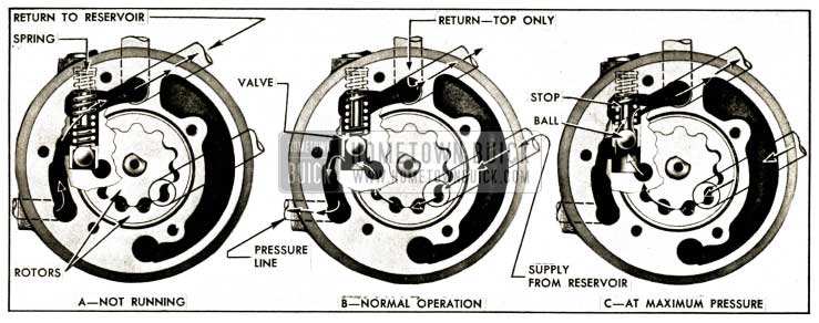
The pump housing contains a drive and driven rotor and a pressure relief valve. The drive rotor, which is keyed to the motor armature shaft, meshes with a free moving rotor which rotates on a different center. As these parts rotate, the pockets formed by their teeth increase and then decrease in size so that fluid is propelled from the entrance to the exit ports in pump housing. The pressure relief valve is located at the exit port. See figure 13-58.
1952 Buick Pump and Pressure Relief Valve Operation
When pump is not running, the pressure relief valve spring holds the valve in position to close the rotor exit port and open a passage between the pressure line port and the reservoir. If a window is lowered or the front seat is moved rearward (by the spring in window lift or seat regulator) the fluid forced out of the hydraulic power cylinder returns to the pump through the pressure line, flows through the valve spring, and drains into the reservoir. See figure 13-58, view A.
When a control switch is closed to operate the top, move front seat forward, or raise a window, the motor and pump start operating to supply fluid pressure. Pressure created by the rotating rotors forces the pressure relief valve outward against spring pressure so that fluid can flow out of pump into the pressure line leading to the appropriate power cylinder. As the valve moves outward it blocks the passage between the pressure line port and the reservoir. See figure 13-58, view B.
Fluid discharged from one end of each folding top power cylinder, as fluid is forced into the opposite end, returns to the pump through a separate line. The fluid returns to the reservoir through a passage in pump housing which by-passes the pressure relief valve. See figure 13-58. view B.
When the top, seat, or window reaches the end of its travel, pump pressure builds up to a maximum of 250-260 p.s.i., forcing the pressure relief valve still farther outward until a stationary stop pushes the ball off its seat in the valve. This provides an opening through which surplus oil returns to the reservoir. See figure 13-58, view C. This relief action prevents the pressure from exceeding the required maximum limit and causing damage to the mechanism.
13-26 1952 BUICK FOLDING TOP HYDRO-LECTRIC POWER SYSTEM
The 1952 Buick power system which operates the 1952 Buick folding top consists of the power unit assembly described in paragraph 13-25, a control switch, a control valve, connecting fluid pipes and control circuit wiring.
The folding top control switch is mounted on the lower edge of instrument panel, and is operated by a rod and knob marked “TOP.” With ignition switch turned “ON,” pushing the knob forward causes the folding top to fold down. When knob is released it returns to the neutral position. The switch controls the power unit motor through the solenoid relay switch as explained in paragraph 13-25, and also controls the control valve as described below.
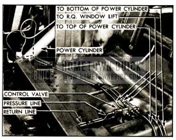
The fluid pipe from outlet side of power unit pump connects to the pressure or inlet port of the control valve, which is located under the rear seat cushion. From the control valve, pipes connect to the top and bottom ends of the folding top power cylinders, and a return pipe connects to the power unit pump and reservoir. Fluid flow through these pipes is controlled by solenoid operated valves inside the valve assembly. Another pipe connects the control valve to the rear quarter window lift cylinders. This line is not controlled by the valves, therefore the rear quarter windows may be operated independently of the folding top. See figure 13-59.
1952 Buick Folding Top Control Valves and Pipes
The top control valve assembly contains two solenoid operated valves which control fluid pressure to the top or bottom ends of the top power cylinders as required to raise or lower the top, depending on the position of the control switch. The valves also control drain back of fluid to the pump reservoir from the ends of power cylinders opposite to those to which pressure is being applied. Operation of the valves in neutral, raising, and lowering the top is explained in subparagraphs b, c, d, below.
1952 Buick Folding Top Power Cylinders
Two hydraulic power cylinders are used to raise and lower the folding top. One cylinder is located in each rear quarter of body below the top hinge.
Each power cylinder is a steel tube closed at each end by crimped-in die castings and enclosing, a piston attached to a rod which extends through the upper end casting. The end castings have rubber seals to form fluid tight joints and have 1/8″ pipe-thread holes for hydraulic fluid pipe connections.
The lower end casting of the cylinder forms a yoke which is hinged by a clevis pin to an anchor bracket on body floor. The upper end casting provides a bearing for the piston rod which is connected to the top linkage mechanism.
When fluid under pressure from the pump passes through the folding top control valve into the lower ends of both power cylinders, the pistons are forced upward to raise the folding top. At the same time, fluid on upper sides of pistons is forced out of cylinders and back through the control valve to the power unit reservoir. When fluid from the pump enters the upper ends of power cylinders, the reverse action takes place and the folding top is lowered.
Neutral Position, Top Stationary
1952 Buick Top Control Valve In Neutral Position
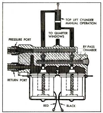
Figure 13-60 shows the control valve in a normal or neutral position. Note that there are three _distinct chambers in the pressure manifold at the upper portion of this assembly; a pressure chamber, a by-pass chamber, and a return chamber. The springs of both solenoids hold the solenoid plungers and the valves in the “up” position, tight against the pressure openings. With the valves in this position, it is possible to operate the folding top by hand due to the by-pass chamber, which directly connects the lines from both sides of the top lift cylinder. Note that the pressure line is always connected directly to the quarter window line.
Operation When Lowering the Top
When the top control switch knob is pulled rearward to lower the top, the power unit motor is started and the forward solenoid (with red wire) in the top control valve is energized. When this solenoid is energized, electro-magnetic force pulls the iron plunger and the valve down so that fluid from the pressure chamber is allowed to travel to the top of the folding top power cylinder, thereby forcing the cylinder piston down to lower the top. Displaced fluid from the bottom of the cylinder returns to the control valve, enters the by-pass chamber, escapes to the return chamber past the opposite valve, and returns to the pump reservoir. See figure 13-61.
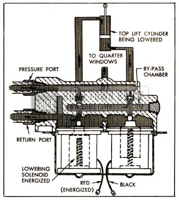
1952 Buick Control Valve When Lowering the Top Lift Cylinder
Operation When Raising the Top
When the top control switch knob is pushed forward to raise the top, the power unit motor is started and the rearmost solenoid (with black wire) in the top control valve is energized. This opens the rear valve so that fluid from the pressure chamber is allowed to travel to the bottom of the folding top power cylinder thereby forcing the cylinder piston upward to raise the top. Displaced fluid from the top of the cylinder returns to the operating valve, enters the bypass chamber, escapes to the return chamber past the opposite valve, and returns to the pump reservoir. See figure 13-62.
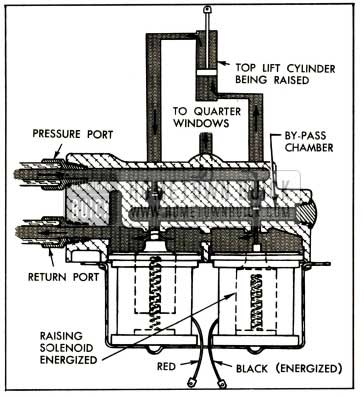
1952 Buick Control Valve When Raising the Top
13-27 WINDOW AND SEAT HYDRO LECTRIC POWER SYSTEMS
The 1952 Buick power systems which operate the windows and the front seat are identical in principle, therefore both systems are covered in this paragraph. The power systems consist of the power unit assembly described in paragraph 13-25, control switches, window lifts or a seat adjuster, connecting fluid pipes and control circuit wiring.
1952 Buick Door and Rear Quarter Window Hydraulic Lifts
A window hydraulic lift is installed vertically between the inner and outer panels of each door. The lift consists of a frame, lift cylinder, and one spring. The lower end of frame is anchored to the door and operating arms on the upper end engage a cam attached to the window lower sash channel. The cylinder is installed in the frame so that its piston rod pushes upward on the operating arms to raise the window glass when fluid is admitted to the cylinder. The spring pulls the operating arms downward to lower the window glass when the valve in cylinder is opened to allow fluid to escape.
The lift cylinder is a steel tube inclosing a piston attached to a rod which extends through the upper cap. The upper cap is crimped in place and sealed to prevent escape of fluid. It houses a saturated felt which excludes foreign matter and acts as a permanent lubricant for the piston rod. The piston rod is rounded at the outer end to fit a formed seat in one window operating arm of the frame assembly.
The solenoid valve which closes the lower end of lift cylinder consists of a solenoid winding and stationary core inclosing a spring-loaded plunger. The plunger contains a disk which is normally pressed against the valve seat by the spring pressure. When the solenoid is energized by current flowing through the closed control switch, the plunger is pulled upward to open the valve and permit the passage of fluid. When the control switch is in neutral position the solenoid is de-magnetized and the spring pushes the plunger down to close the valve.
1952 Buick Hydraulic Seat Adjuster Regulator
A hydraulic seat adjuster regulator assembly is installed below the 1952 Buick front seat to provide power operation of the seat. The seat adjuster regulator assembly consists of a frame, cylinder and one spring.
Except for size, the internal construction of the cylinder assembly is identical with the door window lift cylinder assembly (subpar. a). The seat is moved forward by fluid pressure and moved rearward by spring pressure. To prevent forward movement of the seat during an emergency stop, a rachet mechanism is built into the frame assembly.
Control Switches
The switches which control operation of window lifts and seat regulator are identical in design and operation. Each is a toggle switch which normally stays in neutral or open position. One switch is mounted on the right door for controlling operation of the right door window, and four switches are mounted in a cluster on the left door for controlling all door and rear quarter windows. Starting at the forward (No. 1) switch knob, this switch controls:
- Right rear quarter window
- Left rear quarter window
- Right door window
- Left door window
In addition to the switches on the left door, each rear quarter window is controlled by a single switch on the rear quarter trim panel.
A single switch is mounted on the left end of the front seat frame for control of the seat adjuster regulator.
Neutral Position, Window or Seat Stationary
When the window (or seat) control switch is released it is in neutral position so that all electrical circuits are open. The power unit is stopped and the solenoid valve in regulator or lift cylinder is closed, thus blocking movement of the window (or seat). Since the valve is closed, no movement of window (or seat) can take place when the power unit is operated to move the folding top.
Operation When Raising Window or Moving Seat Forward
Before attempting to move windows or seat, the folding top control knob must be in neutral position so there is no fluid flow in the folding top power system.
When the control switch knob is moved up to raise the window (or forward to move seat forward) the circuits to the solenoid relay switch on power unit motor and to the solenoid valve in the regulator or lift cylinder are closed. The solenoid valve opens to allow fluid to enter the cylinder and the power unit motor and pump start operating. Fluid entering the cylinder causes the piston to raise the window (or move seat forward) against the tension of the return spring.
When switch knob is released the circuits are broken, the power unit stops, the solenoid valve closes and the window (or seat) is held stationary by the oil trapped in the cylinder.
Operation When Lowering Window or Moving Seat Rearward
Before attempting to move windows or seats the folding top control knob must be in neutral position so there is no fluid flow in the folding top power system.
When the control switch knob is moved down to lower the window (or rearward to move seat rearward) the circuit to the solenoid valve is closed, causing the valve to open. The circuit to the power unit solenoid relay switch remains open, thus eliminating action of the power unit pump. When the solenoid valve opens, the pressure of the return spring forces fluid out of regulator or lift cylinder, back through the fluid pipe to the power unit reservoir. This spring action also moves the window down (or seat rearward).
When switch knob is released it returns to neutral position. The solenoid valve circuit is broken, the valve closes, and the fluid trapped in cylinder holds the window (or seat) stationary.
13-28 SERVICE RECOMMENDATIONS
IMPORTANT: Every precaution must be taken to avoid entrance of dirt, water, or any trace of mineral oil into the hydraulic system. To guard against contamination make certain that containers used for fluid are absolutely clean and have not been used for mineral oil.
Before working on hydraulic system be sure to cover adjacent trim and painted surfaces. Hydraulic fluid is injurious to car finish and damage is almost instantaneous.
Hydraulic fluid is inflammable; be careful to avoid dropping fluid on hot manifold or exhaust pipe.
Checking Fluid Level and Adding Fluid
Cars equipped with the 1952 Buick Hydro-Lectric Power System have the power unit reservoir partially drained when shipped from the factory by rail or truck. A tag attached to a radio grille bar gives notice that reservoir must be filled before car is delivered to customer. Since the tag may become detached in handling it is always advisable to check fluid level before delivering any car.
The following procedure must be used whenever it becomes necessary to check fluid level and add fluid.
- Lower the top, move front seat to rearward position, and fully lower all windows.
- Remove fluid reservoir and fill to the fluid level line (1/2″ below top), using Delco Super No. 11 or 12 Brake Fluid. Install reservoir. NOTE: Brake fluid heavier than No. 11 should not be used in extremely cold climates as it will cause sluggish operation of 1952 Buick Hydro-Lectric system.
- Operate the top, all windows and front seat several times each until all air has left the fluid system. If air is present, a chattering noise will be produced when top, windows, or seat are operated. After all air has been expelled, lower the top, move seat back, and fully lower all windows.
- Again remove reservoir and adjust fluid level to the fluid line (1/2″ below top).
- Install reservoir, making certain that gasket is in good condition and that reservoir makes full contact all around. CAUTION: Any leakage of dirt or water into reservoir will cause serious damage in 1952 Buick Hydro-Lectric Power System.
Seasonal Change of Fluid
Hydraulic fluid should be changed once a year, preferably in the Fall. Since the power unit pump reservoir is vented to atmosphere a certain amount of air is drawn into and expelled from the reservoir during operation of the system. Incoming air may bring in a certain amount of fine dust which will accumulate as sludge in the bottom of the reservoir. Normally, a seasonal change of fluid in the reservoir is sufficient, however, if there is very much accumulation of sludge in the reservoir it is important to change fluid in the complete hydraulic system, as follows:
- Lower the top, move seat fully rearward, and fully lower all windows.
- Disconnect battery to avoid accidental operation of power system when pump reservoir is removed.
- Remove and empty pump reservoir. Place a receptacle under pump to catch fluid, then manually raise and lower the top several times. This operation will drain fluid from both ends of the power cylinders.
- Thoroughly clean all sludge from reservoir, using Declene (Group 4.683) or 99% methyl alcohol.
- Fill reservoir to the fluid line 1/2″ from top) with Delco Super No. 11 or 12 Brake Fluid and install on pump.
- Connect battery, using care to properly wind clock (par. 10-66, b).
- Operate the top up and down to pump the fluid into the power cylinders. Additional filling of reservoir will be necessary as the capacity of the two power cylinders is almost double that of the reservoir.
- With reservoir filled to level line, operate top up and down until all air has been expelled from this part of system. If air is present a chattering noise will be produced during operation of top.
- After all air has been expelled from top hydraulic system, operate the front seat and all windows until all air has been expelled from these systems.
- Remove reservoir and adjust fluid level to the fluid line (1/2″ below top). Install reservoir making certain that gasket is in good condition and that reservoir makes full contact all around.
13-29 1952 BUICK HYDRO-LECTRIC SYSTEM TROUBLE DIAGNOSIS
When the 1952 Buick Hydro-Lectric Power System fails to operate properly, two important service inspections should be made before making any other inspections and tests.
- Check the battery and cables as described in paragraph 10-17. If battery specific gravity is below 1.200 the voltage may be sufficient to run the power unit motor but may not be sufficient to operate power cylinder solenoid valves also.
- Check the level of fluid in pump reservoir as described in paragraph 13-28.
Failure of any part of the 1952 Buick Hydro-Lectric Power System can result from three major classes of faults, namely: (1) Mechanical, (2) Electrical, (3) Hydraulic. Before doing any work on the electrical or hydraulic systems it is always advisable to make sure that the fault is not mechanical.
Mechanical faults such as binding or interference of parts can usually be determined by inspection. Electric faults may be determined by the tests given in subparagraph l, below. Hydraulic faults may be determined by the tests given in subparagraph m, below.
Top Will Not Operate
- Mechanical interference due to luggage or other objects; hold-down strap not removed, or top not free from windshield header studs.
- Electrical loose connections in control switch to control valve wiring. Faulty control valve (par. 13-30, c) or faulty switch.
- Hydraulic fluid low (par. 13-28), power unit pump inoperative; stoppage in fluid lines (subpar. m); valves inverted in control valve assembly (par. 13-30, c).
Top Operates In One Direction Only
- Mechanical interference, same as in subparagraph a.
- Electrical faults, same as in subparagraph a.
- Hydraulic power cylinder faulty; stoppage in fluid lines (subpar. m); one valve inverted in control valve assembly (par. 13-30, c).
Window Lift Inoperative
- Mechanical interference from door arm rest screw; misaligned glass run channel or window guide (par. 13-15); window lift not connected to lower sash channel.
- Electrical short or 1oose connection in “BAT,” “MOT” or “CYL” circuit, or cylinder solenoid inoperative (subpar. l); power unit motor inoperative (subpar. k).
- Hydraulic fluid low; hoses crimped or stoppage in fluid pipes (subpar. m); pump pressure relief valve stuck; cylinder piston rod disconnected.
Windows Operate Slowly Upward
- Mechanical binding due to misalignment; glass run channels excessively wet. If window does not fully close, stops are improperly adjusted (par. 13-15 or 13-16) or there is insufficient hydraulic fluid.
- Electrical failure due to low battery (par. 10-17).
- Hydraulic failure_ due to stock pump pressure relief valve; partial stoppage in fluid lines (subpar. m.)
Windows Operate Slowly Downward
If a window moves slowly downward when control switch is in neutral position, the solenoid valve in window lift cylinder is leaking.
- Mechanical binding due to misalignment; glass run channels excessively wet; window lift return spring broken.
- Hydraulic fluid old, congealed, or too heavy for prevailing temperatures (par. 13-28); pump pressure relief valve stuck (subpar. m.)
Window Raises When Top or Seat Is Operated
- Electrical control circuit crossed due to switch “CYL” terminal touching “BAT” terminal.
- Hydraulic pressure too high if more than one window raises (subpar. m).
Two Windows Operate from One Switch
- Electrical control circuit crossed due to switch “CYL” terminals touching.
- Hydraulic pressure too high (subpar. m).
Seat Adjuster Inoperative
- Mechanical interference from object under seat; seat adjuster misaligned; seat adjuster not attached to seat frame or floor.
- Electrical fault same as for window (subpar. c).
- Hydraulic fault same as for window (subpar. c).
Seat Operates Slowly Forward or Rearward
Same as for windows operating slowly upward (subpar. d) or downward (subpar. e).
All Units Operate Slowly in Either Direction
- Mechanical interference due to misalignment.
- Electrical fault due to low battery (par. 10-17).
- Hydraulic fl4id too heavy; pump pressure relief valve stuck; crimped fluid hoses or stoppage in fluid pipes (subpar. m).
Power Unit Inoperative on Any Control Switch
When running, the power unit has a clearly audible whirring sound.
- Battery low (par. 10-17).
- Wiring connections between ignition switch and solenoid relay switch loose, dirty or disconnected (subpar. l).
- Circuit breaker inoperative.
- Solenoid relay switch inoperative.
- Power unit motor inoperative.
Tests of Electrical Circuits
Aside from low battery, failure in the electrical system may be due to circuit faults such as loose or dirty wiring terminals, shorted or grounded wires, inoperative circuit breaker, inoperative switches or solenoids, or inoperative power unit motor. It is necessary to test each part of the affected circuit to determine the cause of failure.
In general, tests may be made in the same manner as for other electrical circuits in the car. A jumper wire may be used to bridge around a wire or unit, or to provide a positive ground. A 6-volt test lamp or a voltmeter may be used to determine whether current is flowing or is available at a given unit. In applying these methods of test refer to the circuit diagrams given in figure 10-120, 10-121 or 10-122 and pay particular attention to color codes specified for wires and terminal markings on the units.
To check operation of switch, wiring and solenoid valve in cylinder of window lift (or seat adjuster) without removing trim pad, turn ignition switch “ON” and push control switch knob up or down. A sharp “click” will be heard when contact is made. If no “click” is heard either the switch, wiring, or solenoid is at fault and each part should be tested individually.
Tests of Pump and Hydraulic Circuits
First make certain that the 1952 Buick hydraulic system and power unit reservoir are properly filled with fluid (par. 13-28).
Disconnect the door window pressure line hose at front side of pump. NOTE: Do not use hose just forward of pressure relief valve plug as this is return line from folding top cylinders. Attach “T” fitting of Hydraulic Pressure Gauge KMO 687 to fitting on pump and connect pressure line hose to “T” fitting. Gauge is now inserted in pump pressure line to door windows.
With ignition switch turned “ON,” operate switch to raise a door window, hold switch on for 10 or 15 seconds after window stops in raised position and note the pressure gauge reading. This should be 250 to 260 pounds.
If pump pressure is below 250 p.s.i. it may be increased by removing the pressure relief valve plug and spring stop and adding a spring washer. See figure 13-66. If pressure exceeds the safe maximum of 260 p.s.i. a spring washer should be removed. Under no circumstance should the valve be set to provide pressure in excess of 260 p.s.i.
If pump pressure cannot be adjusted within specified limits remove power unit for inspection (par. 13-31).
The pressure gauge may be inserted in the pressure line at window lift, top control valve, or top power cylinder to test pressure available at a suspected unit. An appreciable drop in pressure between the pump and the unit indicates a stoppage in the fluid supply line.
When installing pressure gauge at top control valve, connect at port leading to top end of power cylinder if test is made with top raised; if top is down connect at port leading to bottom of power cylinder. See figure 13-59. Make test as previously described. If pressure is below normal, the trouble is either in the hose or pipes leading to control valve, or in the valve itself.
When installing pressure gauge at top power cylinder, connect at top end if test is made with top raised; if top is down, connect to bottom end. If pressure is not normal, the trouble is either in the fluid pipes or fitting between the control valve and cylinder or in the cylinder itself.
13-30 SERVICE OPERATIONS ON 1952 BUICK LIFTS, REGULATORS, VALVES AND CYLINDERS
NOTE: See paragraph 13-31 for service operations on power unit.
Precautions When Disconnecting Fluid Pipes
If fluid pipes are disconnected for any reason, the following precautions must be observed:
- Do not disconnect any fluid pipe without first disconnecting the battery to prevent accidental pumping of hydraulic fluid on finished surfaces or upholstery. Hydraulic fluid will damage lacquer finishes.
- When a fluid pipe is disconnected, there will be a certain loss of fluid and, under certain conditions, the fluid may be pressurized in the line. Always have ample rags or a suitable receptacle to catch this fluid and prevent damage or possible fire; hydraulic fluid is inflammable.
- When a fluid pipe is disconnected, be sure to plug or cap open end of pipe to avoid entrance of dirt, and in case the battery has to be connected for any reason. Also tape ends of any wires that may be disconnected.
- The top must not be operated manually while the pump is disconnected except while cleaning system.
- Before connecting fittings or pipes, sparingly apply a coating of 3-M Fluid Line Sealer to the male threads up to the hex portion of fitting, except for first thread. Connection should be made while sealer is still wet.
- After pipes are connected, operate the top, seat, and windows through several cycles to expel all air and fill reservoir to fluid line (par. 13-28).
Replacement of Oil Seal In Folding Top Power Cylinder
If a fluid leak develops around the piston rod of the folding top power cylinder it may be corrected by replacing the seal, using parts furnished in Oil Seal Package, Group 14.482.
- Raise and lock folding top.
- Remove rear seat cushion and back, then remove rear quarter trim panel.
- Remove nut and bolt attaching piston rod to folding top linkage.
- Check piston rod for burrs and remove any with fine emery cloth.
- Push piston rod half way down and remove the yoke.
- Unsnap oil seal washer retaining clip from groove in cylinder, then pull piston rod out until both steel washers and the felt washer can be removed. Use a sharp pick to remove the rubber oil seal washer. See figure 13-63.
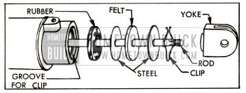
1952 Buick Power Cylinder Oil Seal Parts
Checking and Cleaning 1952 Buick Folding Top Control Valve
If the source of top operating failure has been traced directly to the control valve, remove this assembly and check operation of each solenoid before disassembly. Ground the solenoid cover plate to the body and touch the battery “hot” wire to each solenoid lead separately. Each solenoid will respond with a loud click if it is operating properly. If both solenoids operate properly, disassemble and clean the valves as follows:
- Remove solenoid cover plate, then remove each solenoid by rocking gently until the rubber sealing ring is freed from the pressure manifold. See figure 13-64.
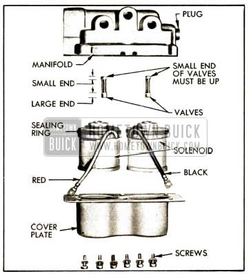
1952 Buick Top Control Valve Disassembled
Replacement of 1952 Buick Front Seat Regulator, Spring or Cylinder
- Remove 1952 Buick front seat assembly (par. 13-21, f).
- Disconnect battery to prevent accidental pumping of hydraulic fluid.
- Disconnect single electric wire at plastic connector.
- Disconnect hydraulic fluid line from regulator cylinder and cap end of line.
- Remove bolts attaching regulator support to floor pan, then remove the support from regulator.
- To replace the regulator spring, hold regulator frame securely in a vise, then use a wood pry bar and loop of heavy wire to unhook old spring and install new one as shown in figure 13-65.
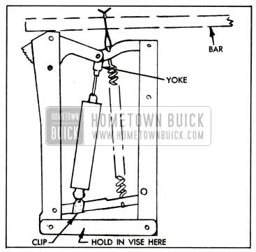
1952 Buick Removing Spring from Regulator
Replacement of 1952 Buick Door Window Lift
- Lower the door window, then disconnect the battery to present accidental operation of power unit.
- Remove door trim pad and the large inspection hole cover (par. 13-19).
- Disconnect window lower sash channel from the window lift cam, raise window glass and prop it in upper position.
- Disconnect electrical wire at the connector, then disconnect and cap the fluid pipe.
- Remove bolts that attach the window lift to door panel and remove lift through the inspection hole.
- To replace the lift spring, hold lift frame securely in a vise, then use a wood pry bar and loop of heavy wire to unhook old spring and install new one as shown in figure 13-65.
- To replace the lift cylinder, hold the lower end of lift frame securely in a vise, remove clips at both ends of cylinder, then push upward on both ends of lift arms to free the cylinder. Install cylinder by reversing this procedure.
- Install window lift by reversing procedure for removal. Seal inspection hole cover before installing trim pad (par. 13-19).
Replacement of 1952 Buick Rear Quarter Window Lift
- Remove rear quarter window (par. 13-16, c).
- Disconnect battery to prevent accidental operation of power unit.
- Disconnect electrical wire at connector, then disconnect and cap the fluid pipe.
- Remove bolts that attach the window lift to rear quarter inner panel. On Series 40 remove the two bolts that attach the sliding support to inner panel at rear edge of inspection hole.
- Remove window lift through inspection hole.
- Install window lift by reversing the removal procedure.
13-31 POWER UNIT SERVICE
Power Unit Types
First production bodies are equipped with the same power unit as used in 1951. Later bodies are equipped with power units having a new “low speed” motor and new pump rotors designed for quieter operation.
The pump on the first type power unit uses a 4-lobe inner (driving) rotor and a 5-lobe outer (driven) rotor. The pump on the second type power unit uses a 10-lobe inner rotor and an 11-lobe outer rotor. At start of production of the second type rotors the inner rotor was one piece; later, the inner rotor was changed to a split or 2-piece construction as shown in figure 13-66. Power units having the split rotor have a blue paint mark on the upper end for identification.
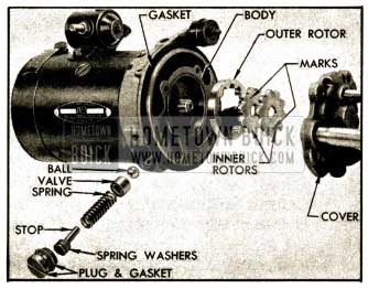
1952 Buick Power Unit Pump Parts-Split Rotor Type
The first type 4-5 lobe rotors are of different thickness than the later 10-11 lobe rotors, therefore the later type rotors cannot be used in the first type pump body. First and second type 10-11 lobe rotors are interchangeable, and the split type only is furnished for service replacement.
Removal of Power Unit
- Disconnect battery, then disconnect wires and ground strap from power unit.
- Remove and drain fluid reservoir, then reinstall reservoir to exclude dirt while handling the power unit.
- Wipe dirt from fittings, disconnect all hoses from power unit, and cap or plug openings to exclude dirt.
- Remove nuts and lockwashers which attach the rubber mountings to brackets on body and remove power unit.
CAUTION: Top must not be manually operated while power unit is removed.
Disassembly of Power Unit
- Thoroughly clean exterior to avoid getting dirt into the pump or motor.
- Remove fluid reservoir and the gasket which fits into a groove in pump body.
- Remove pump cover which is attached to body by five screws and lockwashers. See figure 13-66.
- Remove outer rotor from pump body, then remove inner rotor from armature shaft. Outer rotor may be removed by inserting the bent end of a stiff wire under the inner edge at the cavity in pump body.
- Remove pressure valve plug and gasket, stop, spring washers, spring, valve and ball from pump body. See figure 13-66. It may be necessary to use the bent end of a stiff wire to remove the valve, which is a close fit in the body.
Note the number of spring washers removed, to insure reinstallation of the same number. These washers govern the operating pressure of the pump.
- Inspect rotors, valve parts, and cavities in pump body for foreign matter which may have been the cause of improper operation.
- Scribe a line on pump body and motor frame for reference at assembly, then remove the two through bolts and separate the pump body: from motor frame. This will release the reservoir bail. See figure 13-67.
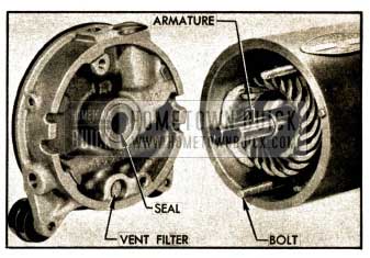
1952 Buick Pump Body Removed from Motor
Cleaning and Inspection of Power Unit Parts
- Thoroughly clean reservoir, pump body and other pump parts using Declene (Group 4.683) or 99% methyl alcohol.
- Clean all motor parts by wiping with clean cloths. The armature and field coils must not be cleaned by any degreasing or high temperature method as damage to insulation will result.
- Inspect pressure relief valve, ball, and valve seat in pump body for dirt, burrs or other conditions which would cause improper operation. Replace valve and ball if worn or otherwise damaged.
- Inspect pump rotors for wear and abrasion and replace if not in good condition. Rotors are serviced in matched sets and must be selected for type of pump as described above (subpar. a).
- Inspect the pump cover and the armature thrust ball which is retained m cover by a washer. If worn, replace cover assembly.
- Inspect pump body for wear or abrasion in rotor cavity. Inspect condition of the armature shaft seal and the bronze vent filter located in upper side of pump body. See Figure 13-67. Replace body assembly if items mentioned are not in good condition, using body specified for type of pump (subpar. a).
- Inspect armature for condition of commutator and windings. Test armature or true up commutator if required, following the procedure specified for generator armature in paragraph 10-28.
- Inspect brushes and leads and replace if worn or damaged.
- Using 6-volt test light with prods, test field coils for grounds or open circuits, and test the field terminal stud and insulated brush holder for grounds in same manner as for other electric motors.
Assembly and Installation of Power Unit
Assemble and install power unit by reversing the procedures for removal and disassembly, paying particular attention to the following items.
- When assembling the motor make sure that all connections are clean and tight at the brush leads and the solenoid switch to motor strap.
- Install pump body on motor frame in its original position according to marks made before removal.
- After installing ball in pump body install the pressure relief valve with the internally shouldered side outward. Install the spring stop with the same number of spring washers as found during disassembly.
- When installing the split type inner rotor, place the piece with the round hole in position first, with the marked surface outward. Place the piece with the “D” shaped hole over end of armature shaft with marked surface outward, then turn so that the marks on both pieces are 180 degrees apart when pieces are meshed with the outer rotor. See figure 13-66.
- When installing power unit the upper rubber mounting may be adjusted up or down as allowed by the slotted hole in bracket on motor.
- When installation is completed, fill reservoir to proper level as specified in paragraph 13-28.
13-62 BUICK FACTORY
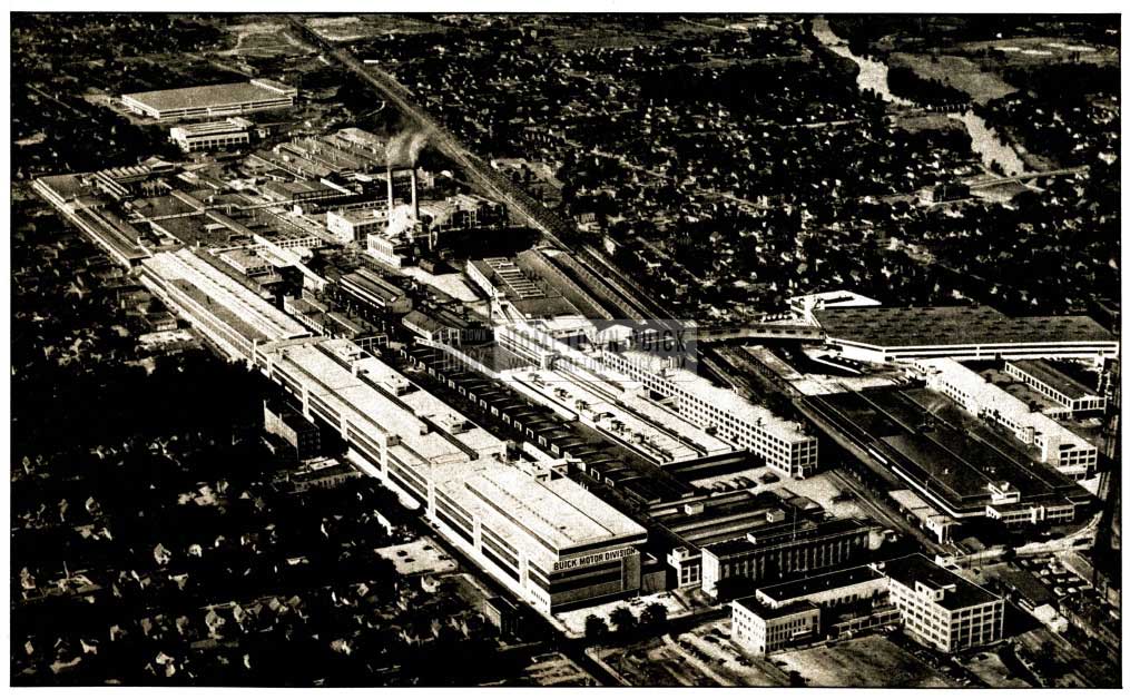
1952 Buick Buick Motor Division in Flint Michigan
Leave A Comment
You must be logged in to post a comment.