SECTION 11-A 1952 BUICK ACCESSORIES MAINTENANCE (OTHER THAN RADIO)
11-1 1952 BUICK HEATER AND DEFROSTER
Description of 1952 Buick Heater and Defroster
The 1952 Buick heater and the defroster are separate units which may be used together or independently as desired. The 1952 Buick underseat heater provides circulation of heated air at floor level. The defroster provides circulation of heated air at shoulder level as well as defrosting of the windshield.
Both units contain water cores which are connected by hoses to the engine cooling system.
The hot water supply is taken from the radiator thermostat housing on the outlet side of engine water pump and is returned to engine cooling system on the inlet side of pump. The volume of hot water flowing through the heater and defroster cores is regulated by a thermostatically actuated temperature control valve mounted on the dash and connected into the water supply line. See figure 11-2.
The 1952 Buick heater is mounted in the floor of body under the right side of front seat. It contains an electric blower which draws air from the body through the hot water core and recirculates the heated air at floor level.
The 1952 Buick defroster is mounted on the right side of cowl under the hood. Outside air is supplied to the defroster by the right hand ventilator duct, which contains an electric blower to provide forced circulation when required. The volume of air passing through the defroster core is controlled by a fly valve inside the defroster housing which is connected by a wire to the control knob on instrument panel. The heated outside air then flows through ducts to openings along the base of windshield where it moves upward against the windshield, which deflects the flow rearward into the body at shoulder level.
1952 Buick Heater and Defroster Controls
The 1952 Buick heater blower is controlled by a “HEATER” switch mounted on the radio speaker grille. When heater switch knob is turned fully counterclockwise the blower is turned off. Turning knob clockwise, the first step gives high speed blower operation and the second step gives low speed operation.
The 1952 Buick defroster blower switch and the air valve control are combined in one unit mounted on the radio speaker grille. Pulling out the “DEFROSTER” knob opens the air valve and turning the knob clockwise turns on the defroster blower. The defroster blower has only one speed.
The heater temperature control is manually set to the desired body air temperature by moving the “HEATER CONTROL” lever located below the radio speaker grille. The control lever has four marked positions: “OFF”, “LOW”, “NORMAL”, and “HIGH”, which are self-explanatory. Once set for a desired body temperature the temperature control unit will automatically maintain this temperature without further adjustment of the control lever.
When the car is cold the temperature control valve stands open to permit maximum flow of water through the heater and defroster cores. As the body air temperature comes up to the level for which the temperature control is set the valve operates to reduce the water flow and maintain the desired air temperature. Since the air temperature will come up to the level as rapidly as existing water temperature will permit it is unnecessary and undesirable to attempt quick warm-up by manipulating the temperature control lever.
When 1952 Buick heating system is in operation a front door ventilator should be opened about %” to let out old air. The opened ventilator should be on opposite side from which wind may be blowing.
Hot water flow through the heater and defroster cores is completely shut off when the temperature control lever is in the “OFF” position. This shuts off all heat when not desired, such as for summer driving. This feature eliminates the need for a shut-off valve in water line at engine.
On Series 40, the control valve for the right hand outside air ventilator is mounted in the defroster housing and ventilator air flows through the defroster core. When it is desirable to warm the incoming air, the temperature control lever may be set at one of the “open” positions. When maximum cooling is desired, however, it is important to set the temperature control lever in the “OFF” position to shut off hot water circulation through the defroster core.
NOTE: To keep out offensive traffic odors and exhaust gases when traveling in congested traffic or when parked behind a car having its engine running, all ventilator and defroster control knobs must be pushed forward to close the valves, and the defroster blower must be turned off.
WARNING-CARBON MONOXIDE
Avoid inhaling exhaust gases when any concentration of these is present in the air, i.e., in a garage, in congested traffic, or when stopped closely behind a vehicle with its motor running. Exhaust gases may have strong odors which normally should give warning of their presence. However, the exhaust gases from some vehicles may not be noticeable under certain conditions and the senses of people react differently. Exhaust gases contain a percentage of carbon monoxide which is a poisonous gas that, by itself, is tasteless, colorless, and odorless.
Temperature Control Lever Adjustment
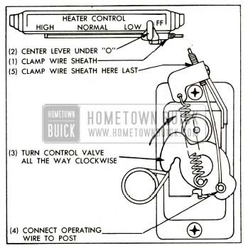
The 1952 Buick temperature control valve is operated by a lever through a sheathed operating wire. To insure full range of temperature control, the valve must act as the stop at both ends of lever travel. Since the operating wire is of fixed length with loops at each end, full range of operation is obtained by clamping the operating wire sheath in proper location on the control lever support and the temperature control assembly, as follows:
- Connect operating wire to control lever and clamp end of sheath flush with edge of clamp on the lever support. Center the control lever under the “0” at “OFF” position, approximately two notches from the end of the lever travel.
- Turn temperature control valve all the way clockwise until the cam locks against the roller. This is the extreme “off” position. Connect operating wire to brass post on valve and clamp the sheath to valve assembly. See figure 11-1.
1952 Buick Temperature Control Lever Adjustment
- Operate the control lever through full range to make certain that the valve provides the stop at both ends.
1952 Buick Heater and Defroster Wiring and Hose Connections
The 1952 Buick heater and defroster blower motors are supplied with current from the “Accessories” terminal of the ignition switch. The supply wire extends from the ignition switch to the fuse block under the cowl where a fuse is located to protect the circuit. Wires from the fuse block connect to the 1952 Buick heater and defroster switches and from the switches to the motors. See 1952 Buick chassis wiring circuit diagrams in Section 10-J.
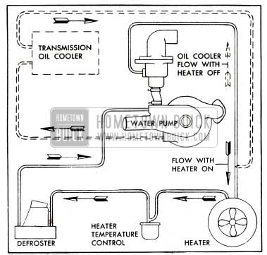
1952 Buick Heater, Defroster, and Oil Cooler Hose Connections
Figure 11-2 shows the heater and defroster hose connections, also the connections to the transmission oil cooler which is used only on Dynaflow cars. When hoses are disconnected for any reason they must be reconnected as shown to obtain proper circulation of water through the various units.
11-2 1952 BUICK WINDSHIELD WASHER
Description and Operations of 1952 Buick Windshield Washer
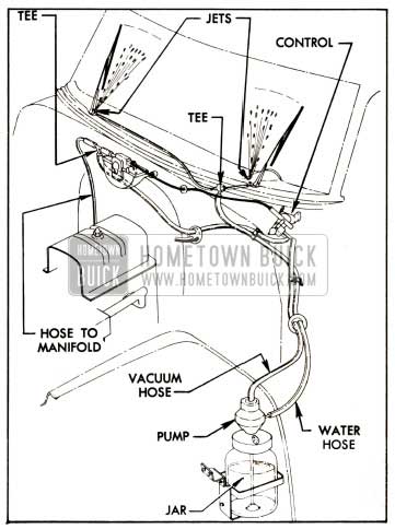
The 1952 Buick washer assembly consists of a vacuum operated water pump and a glass water jar. The assembly is mounted in a bracket attached to the left front fender skirt where it is accessible with hood raised. The inlet at top of pump is connected by a rubber hose to the control mounted on left side of instrument panel, and the control is connected by hoses to the intake manifold. The outlet at side of pump is connected by hoses to the two spray jets located at lower edge of windshield glass. See figure 11-3.
1952 Buick Windshield Washer Installation
The washer is operated, with engine running, by pressing the small button in center of the windshield wiper control, holding for a few seconds, then releasing the button and turning windshield wiper control to “ON” position. Manifold vacuum actuates the washer pump which draws water from the jar and forces it through the jets where it is sprayed on the windshield glasses in the path of the windshield wiper blades. Washer will operate for several seconds before shutting off automatically.
Service Instructions
When the washer is filled for use during seasons when freezing of water may occur, Windshield Washer Anti-Freeze Solvent No. 980740 should be used. Do not use water containing alcohol or other anti-freeze materials as damage to car finish may result.
If the windshield washer does not operate when control valve is used as instructed, check to make sure that water is in the jar. Examine all hoses for leaks or sharp bends, and check hoses for correct connections as shown in figure 11-3.
The windshield washer jets on Series 50-70 have a swivel base and are locked by a jam nut. If the water stream is not properly directed upon the windshield glass its direction may be readily changed. Loosen jam nut slightly, turn jet with a screwdriver as required and tighten jam nut.
11-3 1952 BUICK BACK-UP LAMPS AND SWITCHES
1952 Buick back-up lamps are a factory installed accessory. The installation consists of a lamp mounted in each rear corner of body and a switch mounted on the lower end of steering column. The lamp and switch circuit is protected by a fuse on the fuse block under cowl.
The back-up lamps are controlled by the ignition switch and the back-up lamp switch. When ignition switch is in the “ON” position, the lamps will light automatically when the transmission control lever is placed in the reverse position. The lamps will not light when control lever is in any other position, provided the switch is properly adjusted. This is a legal requirement in many states.
The adjustment of the back-up lamp switch should always be checked after any adjustment of transmission shift controls, or whenever back-up lamps fail to light in Reverse and the bulbs and fuse are okay.
1952 Buick Back-Up Lamp Switch on Cars with Synchromesh Transmission
The 1952 Buick back-up lamp switch on cars equipped with syncro-mesh transmission is located at the lower end of steering column jacket and is operated by the transmission control shaft lever when placed in reverse position.
To provide for manufacturing variations in linkage, the switch operating arm can be adjusted for length. To assure proper switch operation, the transmission shift controls and the switch operating arm must be properly adjusted as follows:
- Adjust transmission shifter and selector rods as described in paragraph 4-9.
- Place transmission gear shift lever in reverse.
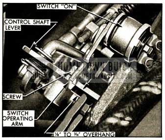
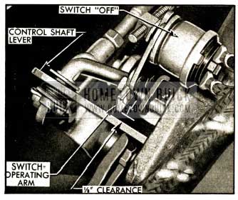
- Loosen hex head cap screw on switch operating arm and adjust length of arm until end of arm extends 1/8″ to 3/16″ beyond front edge of control shaft lower lever. See figure 11-4. Tighten switch arm screw securely.
1952 Buick Position of Switch Operating Arm In Reverse
- Place transmission gear shift lever in second speed position and check clearance between end of switch operating arm and rear edge of control shaft lower lever. The clearance will be approximately 1/8″ if switch is properly adjusted. See figure 11-5.
1952 Buick Position of Switch Operating Arm In Second Speed
1952 Buick Back-Up Lamp Switch on Cars with Dynaflow Drive
The 1952 Buick back-up lamp switch on cars equipped with Dynaflow Drive is mounted on the flange at lower end of the steering column jacket so that the switch operating arm is operated by the transmission control shaft lower lever.
- Check the adjustment of switch by placing transmission control lever in Low (L) position, then checking clearance between switch operating arm and lower edge of control shaft lower lever. Correct clearance is 0 to 1/16″.
- If the specified clearance does not exist, loosen the two switch mounting screws and move switch up or down on mounting bracket as required to obtain clearance, then tighten screws securely. Switch screw holes in mounting bracket are slotted to permit this adjustment. See figure 11-6.
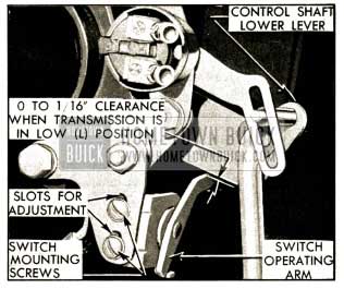
1952 Buick Back-up Lamp Switch Mounting-Dynaflow
11-4 1952 BUICK SAFETY (SPOT) LIGHT
The 1952 Buick safety (spot) light is connected to the No.3 (taillight) terminal of the lighting switch so that the light may be turned on only when the lighting switch is in the “parking” or “driving” positions. The wiring is protected by a fuse located in a splice type fuse holder in safety light lead near the lighting switch.
Instructions for original installation of the 1952 Buick safety light are contained in the accessory package. If the safety light must be removed for any reason observe the following instructions:
Removal of 1952 Buick Safety Light
- Turn lighting and 1952 Buick safety light switches to “off” position.
- Separate safety light lead at fuse holder, remove fuse, and work lead free of supporting clips on forward side of instrument panel.
- Loosen screw “A.” Remove handle screw, handle, bearing, and spring then push pinion up and remove it. Remove screw “A” and pull housing from shaft. See figure 11-7.
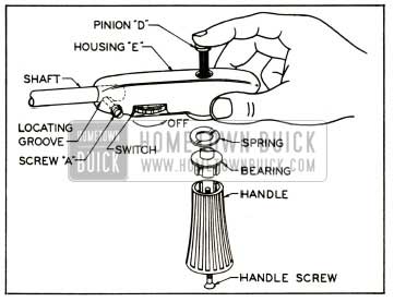
1952 Buick Assembly of Safety Light Pinion and Handle
- Loosen the nut on friction bracket, remove mounting bracket attaching screws and remove safety light from car.
Installation of 1952 Buick Safety Light
- Make sure that mounting bracket fits snugly into the lamp arm and is retained by the small spring on shaft. A small tang of the spring fits into a hole in shaft to hold mounting bracket in place with the correct tension.
- Place the gasket over shaft and against mounting bracket. Rotate lamp head until racks protrude from shaft to equal lengths, then tie rack ends together with string or rubber band.
- Put shaft through hole in door panel and through the friction bracket on inside of door. Install mounting bracket attaching screws, taking care to tighten screws alternately a little at a time until both are uniformly tight.
- Be sure to turn switch to “off” position to avoid damage to switch contacts.
- Remove string or rubber band from racks then slide housing into position on shaft. Do not force housing into position as driving racks may be damaged. Start screw “A” in housing but do not tighten. Screw should be in approximate center of locating groove in shaft.
- Insert the pinion between teeth of driving racks using care to start pinion in center of hole in housing. Pinion should slip into place easily under very light finger pressure. If more than light finger pressure is required, pinion is not located in center of hole in housing.
- Install spring, bearing, handle, and handle screw. Tighten screw securely then rotate handle to see that pinion and racks move freely. Finally, tighten screw “A” securely. See figure 11-7.
- Make sure that safety light lead is looped at door hinge so that it will not be kinked or strained as door is opened and closed. Attach lead to the wire clips on forward side of instrument panel, install fuse in holder and connect fuse holder together. Check to make sure that safety light lead is securely attached to No. 3 terminal of lighting switch.
- Tighten the nut on the inner bracket to adjust the tilting of lamp head and rear view mirror to the owners individual driving needs.
11-5 1952 BUICK AUXILIARY (FOG) LAMPS
When the lighting switch is in parking position, either the parking lamps or the 1952 Buick auxiliary lamps will burn, depending on the position of the auxiliary light switch.
During the installation of the 1952 Buick auxiliary lamps, the white wire to the parking lamps is disconnected from the No. 2 terminal of lighting switch and connected to a 3 1/2″ extension attached to one terminal of the auxiliary light switch. The other terminal of auxiliary light switch is connected by a jumper wire to the No. 2 terminal of lighting switch. The auxiliary lamp wiring is protected by the thermo circuit breaker on the lighting switch, and also by a 14 ampere fuse mounted on the lamp switch.
The 1952 Buick auxiliary lamps must be properly aimed, and should always be checked after any work on the front end sheet metal assembly. The following procedure covers proper aiming of each lamp individually.
- Place car on a level stretch with a light colored surface or aiming screen twenty-five feet (25′) ahead. Draw a horizontal line on this surface four inches (4″) BELOW the level of the fog lamp center. See figure 11-8.
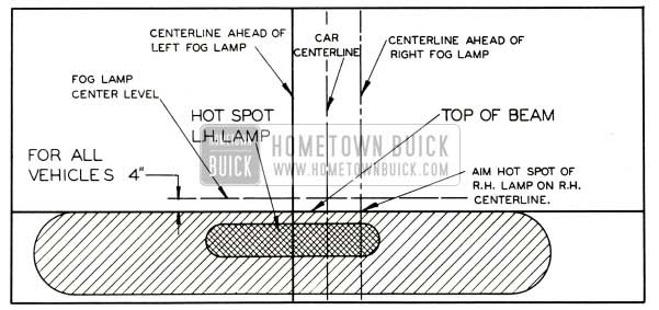
1952 Buick Auxiliary Lamp Aiming Chart-Left Hand Lamp Pattern Shown
- Use a piece of masking tape to mark the exact centerline of the rear window. Sight through the center of the rear window over the radiator ornament to determine the vertical centerline of the car and draw a vertical line at this point.
- Place a vertical line the same distance to the left or right of center as the lamp is from center of the car.
- Aim the lamp (without removing lens) so that the top of the beam is at the horizontal line, and centered sideways on the axis of the lamps, regardless of its position to the left or right of the car. After the lamp has been properly aimed, tighten the lamp nut securely.
Leave A Comment
You must be logged in to post a comment.