SECTION 6-C 1952 BUICK CHASSIS SUSPENSION REPAIR OPERATIONS
6-13 REPLACE AND ADJUST 1952 BUICK STABILIZER LINK GROMMETS
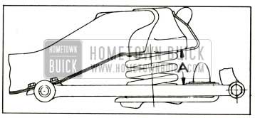
The construction of the 1952 Buick stabilizer links is clearly shown in figure 6-15.
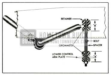
1952 Buick Front Stabilizer Link-Sectional View
To disassemble, remove nut from lower end of the link rod, then remove rod, spacer, retainers, and grommets. When new, the link grommets are 7/8″ free length. When assembling, install rubber grommets dry and use care to center the grommets in the seats on stabilizer shaft and lower control arm plate, also center the retainers on grommets before tightening rod nut. Tighten rod nut to the limit of thread on rod.
When the rod nut is tightened to limit of threads on rod, the overall dimension between sides of grommet retainers as shown at “A” in figure 6-15 should be 1 11/16″. If dimension “A” is not 1 11/16″ when nut is tight, adjust the nut to obtain this dimension. This is important to insure proper riding qualities and stabilization.
6-14 REPLACE AND ADJUST 1952 BUICK FRONT WHEEL BEARINGS
Replacement of Bearings
- Remove wheel with hub and drum assembly. Remove oil seal packing from hub so that inner bearing can be properly cleaned and inspected.
- Wipe old grease out of hub and from steering knuckle spindle. Clean and inspect all bearing parts as described under Bearing Service (par. 1-11 and 1-12), and replace any that are faulty.
- If a bearing cup has to be replaced, drive the old cap out with a punch. Use care when installing the new cap to start it squarely into hub, to avoid distortion and possible cracking.
- When inspecting or replacing bearing cones (inner races) make sure that cones are free to creep on spindle of steering knuckle. The cones are designed to creep on the spindle in order to afford a constantly changing load contact between the cones and the ball bearings. Polishing the spindle and applying bearing lubricant will permit creeping and prevent rust forming between cone and spindle.
- Always install a new wheel bearing oil seal. To avoid damaging the oil seal packing use Packing Expander J 3082 to install bearing inner cone in seal before installation of seal in hub. Push the tapered expander into the seal, place inner cone against expander and push cone into seal until packing bears fully on cylindrical surface of cone. See figure 6-16.
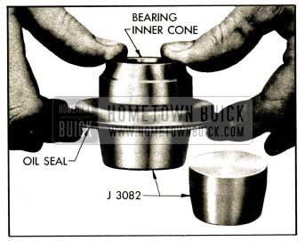
1952 Buick Installing Bearing Cone in Oil Seal with Packing Expander J 3082
NOTE: If wheel is removed from spindle for any reason and new oil seal is not installed, push inner bearing cone into seal before reinstalling wheel on spindle, to avoid damaging the seal packing.
Adjustment of 1952 Buick Front Wheel Bearings
- Tighten spindle nut with 10″ wrench until bearings are preloaded at least one hex, then rotate wheel one revolution to make sure bearings are seated.
- Back off spindle nut until bearings are slightly loose. Tighten nut until all bearing looseness is just removed, then line up nut to nearest cotter hole and install cotter pin. Do not mistake loose king pin bushing, etc., for wheel bearing looseness. CAUTION: Bearing preload must not exceed 1/12 turn of spindle nut.
- Before installation of grease cap in hub, make sure that end of spindle and inside of cap are free of grease so that radio static collector makes a good clean contact. Make sure that static collector is properly shaped to provide good contact between end of spindle and the grease cap.
6-15 REPLACE OR REBUSH 1952 BUICK STEERING KNUCKLE
Removal of 1952 Buick Steering Knuckle
- Remove front wheel with hub and drum assembly.
- Remove brake backing plate and steering arm from steering knuckle. Do not disconnect brake hose but support backing plate out of way to avoid strain on hose.
- Drive out king pin lock pin.
- Remove upper welsh plug from knuckle by piercing with a sharp pointed punch and prying out.
- Drive king pin down and out, which will drive lower welsh plug from knuckle. Remove thrust bearing and shims.
Rebush 1952 Buick Steering Knuckle
New steering knuckles have bushings installed and reamed to size. Bushings are also furnished separately for installation as follows:
- Remove grease fittings and press old bushings from steering knuckle, using Driver J 1382-3 and Press Plate J 1649. If bushings are so tight that pressure springs yoke end of knuckle, place Spacer J 722-2 between yoke ends to one side of bushing.
- With oil hole in bushing in line with hole for grease fittings, and with the short groove on inside of bushing leading toward the expansion plug seat, press new bushing into arm of steering knuckle, using Driver J 1382-3, Spacer J 722-2, and Press Plate J 1649. See figure 6-17.
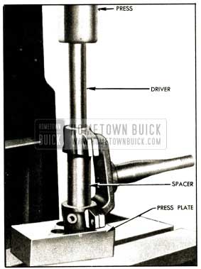
1952 Buick Installing Steering Knuckle Bushing
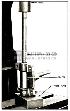
1952 Buick Burnishing Steering Knuckle Bushings
Installation of 1952 Buick Steering Knuckle
- Install 1952 Buick steering knuckle by reversing the removal procedure. Use shims as required between the knuckle support and upper boss of steering knuckle to provide .003″ end play of knuckle on the support. Use new expansion plugs at both ends of king pin.
- Lubricate and adjust front wheel bearings as described in paragraph 6-14.
- Check and adjust caster, camber, and toein (par. 6-30). Be sure to install grease fitting in pivot pin bushing.
6-16 REPLACE UPPER PIVOT PIN AND BUSHINGS
Removal of 1952 Buick Bushings and Pivot Pin
- Place jack under lower control arm, raise wheel off floor, and remove wheel and tire assembly.
- Remove pivot pin bushing clamp bolt in upper control arm, then remove both pivot pin bushings from upper control arm, and remove rubber seals.
- Loosen clamp bolt in knuckle support and remove pivot pin, using 1/4″ hex Allen wrench. NOTE: Tie steering knuckle support to upper control arm to prevent damage to brake hose.
Installation of Pivot Pin and Bushings
- Hold knuckle support in line with hole through control arm and screw pivot pin into knuckle support, with adjusting wrench hole in pin toward the split side of control arm.
- Turn pivot pin until the large diameter section is centralized in knuckle support and tighten the clamp bolt. Install rubber seals on both ends of pivot pin.
- Centralize knuckle support boss in upper control arm yoke and start the externally threaded bushing on threads of pivot pin and into threads of control arm.
- Start the plain (grooved) bushing on threads of pivot pin, then turn the opposite bushing up tight. Turn the plain bushing up until hex is just clear of control arm, then install and tighten clamp bolts.
- Check and adjust caster, camber, and toe in (par. 6-30). Be sure to install grease fitting in upper pivot pin bushing.
6-17 1952 BUICK FRONT CHASSIS SPRING TRIM DIMENSION
Before measuring 1952 Buick front spring trim dimension, bounce front end of car up and down several times to make sure there is no bind in front suspension and to let springs take a natural position.
On a car having service miles the front springs are considered too high or too low when the trim dimension shown at “A” in figure 6-19 is not within the following limits, with car at curb weight.
1952 Buick Front Spring Trim Dimension
All models except 46C, 56C, 76C: 3 3/4” – 4 1/4”
Models 46C, 56C, 76C: 3 1/2” – 4”
NOTE: Add 3/16″ when checking a NEW car. When the trim dimension is found to be too low, correction may be made by installing special shims (Group 7.425), 1/8″ thick, between upper end of spring and the frame. If more than three shims are required, replace the spring.
6-18 REPLACEMENT OF 1952 BUICK CHASSIS FRONT SPRING
Removal of 1952 Buick Front Spring
- Place jack under lower control arm, raise wheel off floor, and remove wheel and tire assembly.
- Disconnect 1952 Buick stabilizer link from lower control arm and disconnect outer end of the tie rod from steering arm.
- Remove lower pivot pin nut, pivot pin, lockwasher, and dirt seals.
- Support car frame by another jack, then slowly lower the jack under lower control arm. This will allow lower control arm to drop low enough to remove 1952 Buick chassis spring.
Installation of 1952 Buick Front Spring
Before installation of 1952 Buick front spring, check the part number which is stamped on one end coil to make sure that spring is correct for the car model, as specified in Group 7.412 of Master Parts List.
- Make sure that the rubberized fabric spring insulator is in place around the spring center cup on frame, and is in good condition.
- Place small end coil of spring over the center cup and as lower control arm is raised, position lower end of spring so that the end coil seats in the recess provided in spring seat. Support lower control arm on a jack.
- Slip the lower pivot pin dirt seals over outer ends of lower control arm. Centralize lower end of knuckle support between outer ends of lower control arm, then install lower pivot pin and lockwasher from front side and tighten securely. Install and tighten nut. Snap dirt seals into place over pivot pin. See figure 6-20.
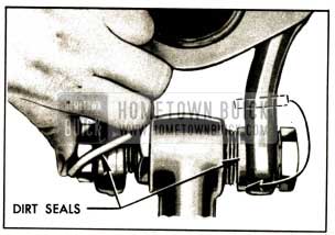
1952 Buick Installing Dirt Seals
6-19 REPLACE OR REBUSH 1952 BUICK LOWER CONTROL ARM ASSEMBLY
If a 1952 Buick lower control arm is bent or broken it should be replaced with a new assembly which includes the shaft, bushings, and dirt seals. The riveted parts of the assembly are not furnished separately. If only the shaft and bushings require replacement these can be obtained separately.
Use all of the following steps for replacement of control arm shaft and bushings. Use only steps 1, 9 and 10 for replacement of control arm and shaft assembly.
- Remove front chassis spring (par. 6-18) then remove lower control arm assembly from frame front cross member.
- Unscrew bushings and remove shaft from control arm.
- Check the distance between inner ends of control arm. The normal dimensions is 11 1/4″ plus or minus 1/22″, from inside to inside. See figure 6-21.
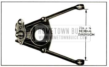
1952 Buick Correct Spacing of Control Arm Inner Ends
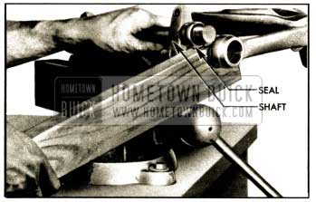
1952 Buick Springing Arm Over End of Shaft
1952 Buick Installing First Bushing
6-20 1952 BUICK CHASSIS REAR SPRING TRIM DIMENSION
Before measuring the 1952 Buick rear spring trim dimension, bounce rear end of the car up and down several times to make sure there is no bind in rear suspension and to let spring take a natural position. If car has enough mileage to be broken in, the spring trim dimension “A” (fig. 6-24) should then be within the following limits, with car at curb weight:
Models 46C, 56C, 76C: 5 1/2” – 6 1/2”
Models 56R, 59, 76R, 79R: 5 5/8” – 6 3/8”
All other Models: 5 13/16” – 6 9/16”
NOTE: When checking NEW car add 3/8″.
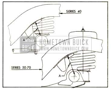
1952 Buick Rear Spring Trim Dimension
If trim dimension is less than specified or additional height is required to prevent excessive “bottoming” in exceptional cases, install additional spring insulators (group 7.545), divided between upper and lower ends of spring. If more than three additional shims are required replace the spring. Installation of new springs should not increase spring trim dimension “A” more than 1″ over specified maximum limit.
6-21 REPLACEMENT OF 1952 BUICK CHASSIS REAR SPRINGS
Replacement Procedure
- Disconnect links from 1952 Buick rear shock absorber arms.
- Hoist rear end of car until all load is off rear springs and place floor stands under frame for safety.
- Remove spring clamps at lower and upper ends and remove spring. Lower clamp bolts on Series 50-70 have left hand threads.
- Check part number stamped on one end coil of new spring to make certain that spring is correct for the car model as specified in Group 7.503 of Master Parts List.
- Be sure that spring insulator in upper seat is in good condition then attach upper end of spring using spring clamp, bolt insulator, flat washer, lockwasher and bolt in the order named. Attach lower end of spring with spring clamp, lockwasher and nut (Ser. 40) or bolt (Ser. 50-70).
- Lower rear end of car and attach links to 1952 Buick shock absorber arms.
Use of Special Overload Rear Springs
Special 500 pound overload rear springs are available for service installation in cases where heavy loads are carried or heavy trailers are towed. Overloading any series rear axle in excess of 500 pounds is not recommended.
In estimating rear spring overloads, place rear wheels of car on scale, with car at curb weight and no load in rear compartment other than spare wheel and tire. After obtaining weight, hook trailer to car, or place desired load in rear compartment, and read scale again. The additional weight is the amount of overload on springs and rear axle.
Trailer design, and distance that trailer coupling is located to rear of rear axle center line, are the major factors governing effective trailer overload. Instructions for attaching trailers to
Buick cars may be obtained from Buick Motor Division Factory Service Department.
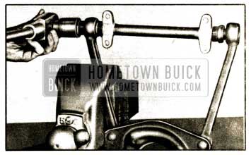
6-22 REPLACE OR REBUSH 1952 BUICK RADIUS ROD
- Support rear end of car on jacks placed under rear axle housing so that weight of car will be on rear springs.
- On right end, remove radius rod pin nut and lockwasher, then disconnect pin support from bracket on axle housing. On left end, remove pin nut and lockwasher then remove pin support (Ser. 40) or frame bracket brace (Ser. 50-70). Remove rod and bushings from pin on frame bracket.
- Check radius rod for twist and bow, which should be within limits shown in figure 6-25. If rod is twisted or bowed it must be straightened without heating; otherwise, replace with a new part.
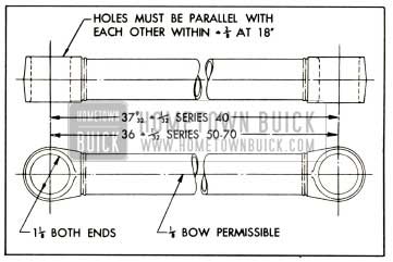
1952 Buick Radius Rod Dimensions
6-23 CHECKING AND FILLING 1952 BUICK SHOCK ABSORBERS
CAUTION: Thoroughly clean off all dirt from top of 1952 Buick shock absorbers, front and rear, to avoid getting dirt into absorbers when filler plugs are removed. Blow off all loose dirt from the surrounding area of chassis so that dirt will not be brushed off into filler opening while filling shock absorbers. A few grains of dirt can readily plug a 1952 Buick shock absorber valve and seriously affect performance of the unit.
Filling 1952 Buick Front Shock Absorbers
Remove filler plugs and add fluid until it overflows, using only G. M. or Delco Shock Absorber Fluid. Install plugs loosely to exclude dirt and bounce front of car up and down by front bumper to force out any air in cylinders. Repeat addition of fluid and bouncing of car until no more fluid can be added, then install filler plugs securely. An air space is built into the 1952 Buick front shock absorber body above the filler opening to provide for expansion of the fluid when hot.
Filling 1952 Buick Rear Shock Absorbers
Remove filler plugs and add G. M. or Delco Shock Absorber Fluid until level is 1/2″ to 23/32” below filler openings. Install plugs loosely to exclude dirt and bounce car up and down by rear bumper to force out any air in cylinders. Add additional fluid, if necessary, until fluid level is 1/2″ to 23/32″ below filler openings, then install filler plugs securely.
1952 Buick shock absorbers require some air space for expansion of fluid when hot, otherwise fluid may be forced out. This air space must be provided in rear absorbers by leaving fluid level 1/2″ to 23/32″ below filler opening. Correct level in rear absorbers may be conveniently obtained by use of Shock Absorber Gun KMO 1026 and Adapter J 1611. Use gun to fill absorber and place the adapter on gun nozzle to suck out surplus fluid.
Checking for Fluid Leaks in Shock Absorbers
An empty or almost empty shock absorber indicates leakage which should be located and corrected.
To check for leaks, clean off the entire body with an air hose, then fill shock absorber as described above. Drive car over a rough road for a few blocks, then inspect the unit with a good light. A slight leak at the seal around cam shaft is of little consequence and is due to initial expansion after filling. Leakage at end caps of front shock absorber will require removal of unit for installation of new gaskets. Leakage at gaskets of rear shock absorbers may be corrected by installation of new gaskets without removal of the unit.
6-24 REPLACE 1952 BUICK SHOCK ABSORBERS OR VALVES
In 1952 Buick front shock absorbers, the end cap gaskets may be replaced to correct fluid leaks, and the valves may be replaced, if the proper special tools are available in the shop.
In 1952 Buick rear shock absorbers, the cover or gasket, rebound and compression valves, valve nuts and gaskets may be replaced with ordinary hand tools. The intake valves in pistons cannot be replaced.
If any other parts replacements or repairs are required in either a front or rear shock absorber, a complete replacement unit is required. Replacement shock absorbers are available through Buick Parts Warehouses on an exchange basis.
1952 Buick shock absorber calibrations as furnished in production, and as given in Chassis Suspension Specifications (par. 6-1) have been carefully engineered to provide the best ride control over a wide range of driving conditions. Substitution of other calibrations should not be attempted under any circumstances, unless authorized by Buick Motor Division.
Removal and Installation
A 1952 Buick front shock absorber can be removed by removing the knuckle support upper pivot pin (par. 6-16) and the three shock absorber attaching bolts. The outer bolt (located at upper end of chassis spring) may be removed with a socket wrench and extension through the opening in lower control arm spring seat. When 1952 Buick shock absorber is installed by reversing removal procedure, caster, camber, and toe-in must be checked and adjusted (par. 6-30).
A 1952 Buick rear shock absorber can be removed by disconnecting link from shock absorber arm, and removing shock absorber from brake backing plate after removal of brake drum.
Removal of 1952 Buick Front Shock Absorber Valves
- Thoroughly clean outside of shock absorber, then mount it on Holding Fixture J 895. Do not hold shock absorber in a vise.
- Remove end cap, using End Cap Wrench J 766. See figure 6-26. Do not use a pipe wrench as this will ruin the cap.
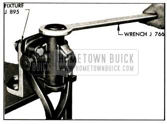
1952 Buick Removing Front Shock Absorber End Cap
Installation of Valve in 1952 Buick Front Shock Absorber
- Mount 1952 Buick shock absorber on Holding Fixture J 895. Install compression and rebound valve discs, valves and retainers, using Valve Installing Tool J 896-A to install the retainers. The blade of tool is placed in the gap in retainer and it holds valve spring down while retainer snaps into notches in piston. See figure 6-27.
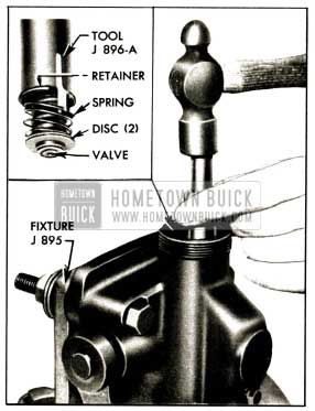
1952 Buick Installing Front Shock Absorber Valve Retainer
Replacement of 1952 Buick Rear Shock Absorber Valves
After thoroughly cleaning outside of 1952 Buick shock absorber, remove rebound or compression valve as required by removing valve nut and gasket. The rebound valve consists of one assembly. The compression valve consists of an orifice assembly, blow off spring, static valve, and static spring, which must be installed in the order given. See figure 6-7.
6-25 REMOVAL AND INSTALLATION OF TIRE AND TUBE
With the synthetic tubes and drop center rims, care must be taken in removal and installation to avoid injury which would result in early failure of tube in service. The following instructions must be carefully followed.
- Deflate tube completely. Loosen both beads from rim ledges, using tool if necessary. Insert two tire tools about 8 inches apart between bead and rim flange near valve stem and pry short lengths of bead over flange. See figure 6-28, view A.
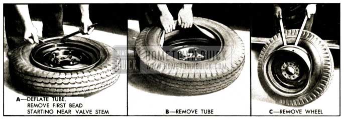
1952 Buick Removing Tire and Tube
Then, leaving one tool in position, follow around rim with the other tool, taking small bites, to remove remainder of bead.
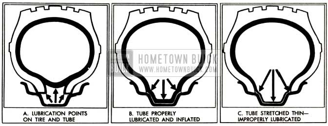
1952 Buick Lubrication and Inflation of Tube
Leave A Comment
You must be logged in to post a comment.