SECTION 5-B 1952 BUICK REAR AXLE TROUBLE DIAGNOSIS
5-3 ELIMINATION OF EXTERNAL NOISES
When a 1952 Buick rear axle is suspected of being noisy it is advisable to make a thorough test to determine whether the noise originates in the tires, road surface, front wheel bearings, engine, transmission, or rear axle assembly. Noise which originates in other places cannot be corrected by adjustment or replacement of parts in the 1952 Buick rear axle assembly.
Road Noise
Some road surfaces, such as brick or rough surfaced concrete, cause noise which may be mistaken for tire or rear axle noise. Driving on a different type of road, such as smooth asphalt or dirt, will quickly show whether the road surface is the cause of noise.
Tire Noise
Tire noise may easily be mistaken for rear axle noise even though the noisy tires may be located on the front wheels. Tires worn unevenly or which have the surfaces of the nonskid divisions worn in saw-tooth fashion are usually noisy, and may produce vibrations which seem to originate elsewhere in the vehicle. This is particularly true with low tire pressure. Some designs of non-skid treads may be more noisy than others, – even when tires are new.
Test for Tire Noise
Tire noise changes with different road surfaces but rear axle noise does not. Inflating all tires to approximately 60 pounds pressure, for test purposes only, will materially alter noise caused by tires, but will not affect noise caused by the rear axle. Rear axle noise usually ceases when coasting with transmission in_ neutral at speeds under 30 miles per hour; however, tire noise continues but with lower tone as car speed is reduced. Rear axle noise always changes when comparing “pull” and “coast,” but tire noise remains about the same.
Front Wheel Bearing Noise
Loose or rough front wheel bearings will cause noise which may be confused with rear axle noise; however, front wheel bearing noise does not change when comparing “pull” and “coast.” Front wheel bearings may be easily checked for noise by jacking up the wheels and spinning them, also by shaking wheels to determine if bearings are loose.
Engine and Transmission Noises
Sometimes a noise which seems to originate in the 1952 Buick rear axle is actually caused by the engine or transmission. To determine which unit is actually causing noise, observe approximate car speeds and conditions under which the noise is most pronounced, then stop car in a quiet place to avoid interfering noises. With transmission in neutral and clutch engaged, run engine slowly up and down through engine speeds corresponding to car speeds at which the noise was most pronounced. If a similar noise is produced with car standing it is caused by the engine or transmission, and not the rear axle. With trans- mission still in neutral, run engine through speeds while slowly disengaging and engaging clutch. If noise disappears with clutch disengaged, it is caused by transmission. If noise continues regardless of clutch position, it is caused by the engine.
5-4 1952 BUICK REAR AXLE NOISES
If a careful test of the car shows that the noise is not caused by external items as described in paragraph 5-3 above, it is then reasonable to assume that the noise is caused by the 1952 Buick rear axle assembly.
Testing 1952 Buick Rear Axle
The 1952 Buick rear axle should be tested on smooth road to avoid road noise. It is n ever advisable to test rear axle for noise by running engine with transmission in high gear with rear wheels jacked up. Without normal loading to take up allowable clearances of parts and the cushioning afforded by the tires, the rear axle will be quite noisy when operated by power while resting on car stands.
Rear Wheel Bearing Noise
Noises in the 1952 Buick rear axle assembly may be caused by faulty rear wheel bearings, faulty differential or pinion shaft bearings, differential side gears and pinions worn, or by a mismatched, improperly adjusted or scored ring and pinion gear set.
A rough rear wheel bearing produces a vibration or growl which continues with car coasting with transmission in neutral. A brinnelled rear wheel bearing causes a knock or click approximately every two revolutions of rear wheel since the bearing rollers do not travel at the same speed as the rear axle and wheel.
Pinion Bearing Noise
Rough or brinnelled pinion bearings produce a continuous whine starting at a relatively low speed. The noise is most pronounced on light load drive between 18 and 25 miles per hour.
Differential Side Gear and Pinion Noise
Differential side gears and pinions seldom cause noise since their movement is relatively slight on straight ahead driving. Noise produced by these gears will be most pronounced on turns.
Ring and Pinion Gear Noise
Noise produced by the ring and pinion gear set generally shows up as drive noise, coast noise, or float noise.
- Drive noise is most pronounced on constant acceleration through the speed range.
- Coast noise is most pronounced when car is allowed to coast through the speed range, with clutch engaged (synchromesh) or transmission in Direct Drive (Dynaflow).
- Float noise is most pronounced while holding the car speed constant at various speeds.
- Drive, coast and float noises will be very rough and irregular if the differential or pinion shaft bearings arc rough, worn, or loose.
5-5 CHECKS FOR CAUSE OF 1952 BUICK REAR AXLE NOISE
If there is any doubt about the cause of noise in the 1952 Buick rear axle assembly, the following progressive checking procedure will assist in determining the cause. The paragraph numbers given in the checks refer to paragraph in which re pair procedure is given.
- Place car stands solidly under 1952 Buick rear axle housing so that wheels are clear of floor.
- Spin rear wheels by hand while listening at hubs for evidence of rough or brinnelled wheel bearing. Care must be used to avoid mistaking differential gear noise for bearing noise. If in doubt, remove rear axle shafts and bearings for examination (par. 5-9).
- If r ear wheel bearings are not noisy, or they are not responsible for all rear axle noise, drain and flush rear axle housing (par. 1-8) and l eave housing cover off.
- Check matching numbers on ring and pinion gears to make sure that they are matched set (par. 5-19).
- Examine gear teeth for chips or scores and for proper gear tooth contact (par. 5-6 & fig. 5-2). Check ring gear lash with dial indicator (par. 5-23).
- Check differential side bearings for proper preload as follows. Loosen all bearing cap bolts one full tum, tighten to 20 ft. lbs. torque, then back off all 4 bolts 1/2 turn. Remove bearing adjuster lock on one side and mark adjuster in line with lock slot in bearing cap. Slowly back off adjuster until bearing outer race stops turning, noting number of notches required to reach the breaking point. The number of notches, or bearing preload should be 2 1/2 to 3. If bearing does not tum as adjuster is backed off, tighten adjuster until bearing starts to turn, noting number of notches required to just start bearing turning. This will indicate the number of notches that bearing was loose. Bearings should be given preload of 2 1/2 to 3 notches, using procedure given in paragraph 5-16.
- If gear set is not mismatched, worn, or scored, and checks made in steps 5 and 6 above do not show cause for noise, remove differential ring gear and case assembly (par. 5-10). Inspect differential side bearings (par. 1-11 and 1-12).
- Test for pinion shaft bearing wear as described in paragraph 5-10 step 2, and check pinion setting (par. 5-21).
- If pinion shaft bearings are worn or of doubtful condition or pinion is not properly set, remove pinion and propeller shaft assembly (par. 5-10). Replace bearings or reset pinion as required.
5-6 CHECKING GEAR TOOTH CONTACT
The procedure described below may be used before disassembly to check gear tooth contact existing between ring and pinion gears, to determine whether improper adjustment is cause of noisy gear operation.
The procedure also may be used check adjustment following installation of gear set when the specified tools are not available; however, it is not recommended as a regular substitute for these tools. The use of the pinion setting gauge and dial indicator as prescribed in installation instructions will provide a more accurate adjustment of ring and pinion gears and will save considerable time.
- Drain and flush rear axle housing (par. 1-8) and leave housing cover off.
- Wipe ring and pinion gear teeth dry with clean cloth. Paint ring gear teeth lightly and evenly with red lead or white lead of suitable consistency.
- Lightly apply the brakes so that rear wheels have a one-hand drag, then run the engine slowly with transmission in first gear, then in reverse, for just a few seconds.
- Compare marks produced on gear teeth with marks shown in views A through E in figure 5-2.
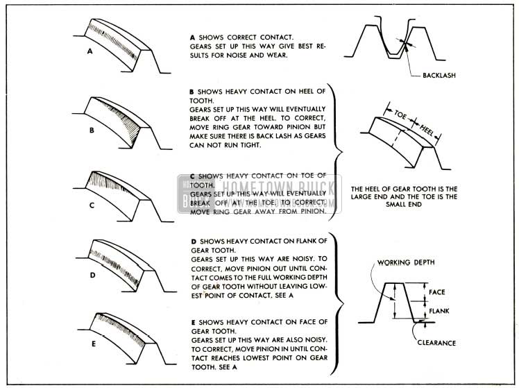
1952 Buick Gear Tooth Contact Corrections
Marks should be as shown in view A. If marks are as shown in views B, C, D, or E, the gears are not correctly adjusted and may be noisy in operation.
- Gears marked as shown in views B, C, D, or E should be adjusted as indicated opposite these views in figure 5-2. Adjustment will be satisfactory in most cases where gears are comparatively new and not improperly worn or scored. If gears have been run long enough to wear the teeth appreciably, however, it is unlikely that adjustment will produce quiet operation.
- Procedure for sidewise adjustment of ring gear is given in paragraph 5-16. If adjustment of pinion is required it will be necessary to remove pinion and propeller shaft and change total thickness of pinion bearing shim, as described in paragraph 5-15 (e).
- After making the adjustment indicated, re-paint ring gear teeth and run gears again as described in step 3, above. Final marking should be as shown in view A, figure 5-2. When proper tooth contact is obtained, wipe lead from gears and carrier with cloth moistened with clean gasoline or kerosene. Wipe out housing with clean cloths.
- Pour a liberal quantity of rear axle lubricant on gears and bearings, and turn rear wheels to work lubricant into all surfaces.
- Install housing cover, using a new gasket and coating bolt threads with white lead to avoid oil leaks. Align filler plug with first bolt hole to right of lower center bolt hole in housing. This change from straight down position increases oil level to 4 pints.
- Remove car stands so that car is level, and fill housing to filler plug opening with approved rear axle lubricant. See paragraph 1-8.
Leave A Comment
You must be logged in to post a comment.