SECTION 2-D 1952 BUICK CYLINDER HEAD AND VALVE MECHANISM SERVICE
2-14 1952 BUICK VALVE LASH ADJUSTMENT
NOTE: This procedure applies only on Series 40 engines used with Syncromesh transmissions; these engines have plain sleeve valve lifters. All other engines have hydraulic valve lifters, indicated by a label on rocker arm cover, stating-“This Engine Equipped with Hydraulic Lifters.”
For maximum performance in engines equipped for adjustable valve lash, it is imperative that the ROAD OPERATING VALVE LASH BE UNIFORMLY .015″.
Oil, water and engine temperatures must be stabilized or brought to normal operating temperatures before the valves can be properly adjusted for uniform lash. When an engine is warmed up by running without load in the shop, the oil, water and engine temperatures level off at different points than those obtained on the road; therefore, a wider lash adjustment is required in the shop adjustment.
NOTE: An alcohol base anti-freeze in the cooling system will boil before the temperatures become properly stabilized when running engine in the shop; therefore, such anti-freeze must be drained and the cooling system filled with water until valve lash operation is completed , after which the anti-freeze must be reinstalled.
The following procedure must be carefully followed when adjusting valves in the shop, in order to obtain the specified road operating lash.
- Loosen radiator cap to prevent excessive water temperature build-up. Start engine and set speed at a minimum of 700 RPM. NOTE: A lower speed during warm-up will not provide proper circulation through the engine to uniformly stabilize the water temperature.
- Run the engine for 20 minutes. This will bring the oil, water and engine temperatures to a point where change of lash caused by expansion of engine parts will level off and the lash will remain fairly constant for a period of about 10 minutes. During this time the valve lash can be checked and adjusted as required.
- Set engine to idle at 350-400 RPM. Remove rocker arm cover and make sure that valves are being properly supplied with oil.
- Starting at rear of engine, check the lash of all valves with a .017″ and an .018″ feeler gauge. The .017″ gauge should pass between the valve stem and rocker arm without sticking, but the .018″ gauge should not pass through.
CAUTION: Feeler gauges must be smooth and straight.
- Where the lash is either too tight or too loose, loosen the lock nut and adjust the ball stud until a slight drag is felt on a .017″ feeler gauge placed between the valve stem and rocker arm. Tighten lock nut and recheck lash with the .017″ “go” and .018″ “no go” feeler gauges. Quiet valve action d e pends on uniform valve lash. Valve lash must not be reduced below the minimum clearance specified.
- Adjust engine idle speed at 450 RPM, then stop engine.
- Install rocker arm cover, making sure that gasket is in good condition and properly placed to prevent leakage of oil. Tighten radiator cap.
2-15 1952 BUICK HYDRAULIC VALVE LIFTER SERVICE
Removal of 1952 Buick Hydraulic Lifters
When an inspection indicates that the valve lifters may contain dirt or varnish it is advisable to remove all lifters for cleaning and inspection; otherwise, it will be satisfactory to remove only the lifters that are not operating properly.
- Remove 1952 Buick air cleaner (Ser. 40-50 only), rocker arm and push rod covers.
- When removing all or a majority of the valve lifters, remove the rocker arm and shaft assembly from 1952 Buick cylinder head, then remove all push rods.
When removing only a few of the valve lifters, loosen lock nut and turn ball stud out of rocker arm (above each lifter being removed) until arm can be moved aside far enough to clear the push rod. Remove push rod.
- Insert Hook J 5096 through hole in push rod seat and remove valve lifter. See figure 2-12.
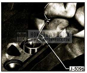
1952 Buick Removing Lifter with Hook J 5096
If a lifter cannot be removed because it is burred or mushroomed on lower end it will be necessary to remove the camshaft so that the lifter can be removed from below. The lifter guide hole may be damaged if a mushroomed lifter is driven up through it.
If a lifter cannot be removed with Hook J 5097 because of varnish, then use Remover J 5094 in the following manner.
- Insert a nail (1 3/8″ long) through hole in push rod seat to hold the check ball off its seat, then lightly place Remover J 5094 on valve lifter and turn the knurled knob until the flange on remover shaft drops down inside the plunger retainer.
- Turn knob to align screwdriver slot with handle of remover, so that flats on remover body match the straight sections of plunger retainer. See figure 2-13, view A.
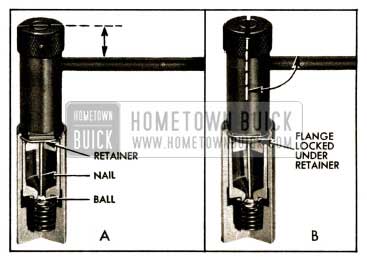
1952 Buick Application of Remover J 5094
- Using a long screwdriver through the push rod hole, push remover down and turn the knob 1/4 turn in either direction. This will depress lifter plunger and engage the flange on remover shaft under the straight section of plunger retainer. See figure 2-13, view B.
- Work remover and lifter up and down to scrape off varnish ring on lower end of lifter body. Do not use force as plunger retainer may be pulled out of its groove in lifter body. If the varnish ring is too heavy, pour cleaning solvent (subpar. c) on top of the lifter and let it soak down to soften the varnish so that the lifter may be removed.
- If less than a full set of lifters is being removed, immediately disassemble and inspect one or two of the first ones removed (subpar. b). If dirt or varnish is present in these lifters, remove all lifters for thorough cleaning and inspection.
NOTE: lf dirt is found in lifters be sure to thoroughly clean the 1952 Buick cylinder head , rocker arm and shaft assembly, and 1952 Buick cylinder block to avoid a repetition of lifter trouble.
- Examine the cam contact surface at lower end of each lifter body. If this surface is excessively worn, galled, or otherwise damaged, discard the lifter assembly. In this case also examine the mating camshaft lobe for excessive wear or damage by inserting a finger through the lifter guide hole.
Disassembly of 1952 Buick Hydraulic Lifters
Insert the spring loaded pin of Plunger Depressor J 5097 through hole in push rod seat to hold the check ball off its seat, then depress plunger and seat far enough to remove plunger retainer. See figure 2-14.
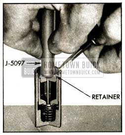
1952 Buick Removing Retainer with Depressor J 5097
Remove push rod seat and plunger from body. If plunger is stuck in body, place the lifter in large end of Plunger Remover J 5092, with plunger inward. While holding lifter with thumb, rap the open end of remover against a block of wood with just enough force to jar the plunger from body. See figure 2-15.
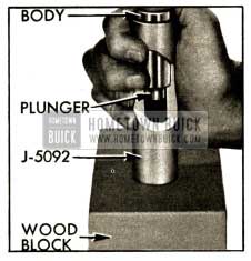
1952 Buick Removing Stuck Plunger with Remover J 5092
Drain oil out of body into a waste can and then remove the ball, retainer and spring. A strainer placed over waste can will prevent dropping these parts into can.
Place all parts of each lifter in a separate compartment of a tray from Cleaning Tank J 5093. The body and plunger are selectively fitted to each other and must not be interchanged with parts of other lifters. Keeping all parts of the lifter together until cleaned and inspected will aid in diagnosing cause of improper operation.
Cleaning Tank J 5093 and Cleaning Fluids
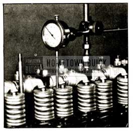
Cleaning Tank J 5093 is designed to permit a systematic and thorough cleaning of hydraulic lifter parts. It provides three compartments for cleaning fluids, two 16-compartment cleaning trays, one small tray for special tools, and a removable cover. The two cleaning trays allow one set of lifters to be soaking while another set is being worked on. The cover, when placed on bench in front of tank, provides an easily cleaned working surface. See figure 2-16.
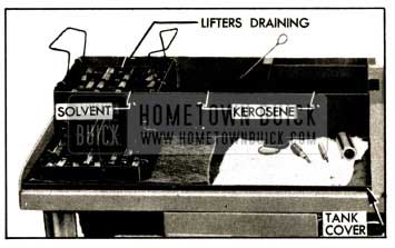
1952 Buick Tank J 5093 Set Up for Cleaning Lifter Parts
The left hand compartment of tank is for cleaning solvent in which parts are soaked after disassembly. The solvent required should either dissolve the varnish deposit on lifter parts or soften the varnish M that it can be removed by wiping, after soaking for not longer than one hour. Gulf Motor Flush, or an equivalent solvent, will effectively clean lifter parts.
Then selecting a cleaning solvent, careful consideration should be given to its effect upon the hands. The directions and safety precautions of the manufacturer should be understood and observed to avoid personal injury. A wise safety rule is to wear rubber gloves when handling parts that are wet with cleaning solvent.
The middle compartment of tank is for clean kerosene to be used for cleaning parts after removal from the cleaning solvent. The right hand compartment is for clean kerosene to be used exclusively for final rinsing of parts just before assembly.
When the cleaning tank is not being used the cover should be installed to exclude dirt from the cleaning fluids. As a further precaution, do not use the tank for any parts except hydraulic valve lifters.
To avoid early contamination and deterioration of the cleaning solvent a separate pan of suitable size should be provided so that a tray of lifter parts can be flushed in kerosene before it is placed in the solvent. See figure 2-16.
Cleaning 1952 Buick Hydraulic Lifter Parts
- Rinse the tray full of lifter parts in a pan of kerosene to remove as much oil as possible. This will reduce contamination of the cleaning solvent and extend its effective life.
- Submerge the tray and parts in the cleaning solvent in left hand compartment of Cleaning Tank J 5093 and leave to soak for approximately one hour. The time required will depend on the varnish on lifter parts and the effectiveness of the solvent.
- After the varnish has dissolved or has softened sufficiently to permit removal by wiping, raise the tray and suspend it above the solvent by means of the hooks on tray handles. Allow tray and parts to drain so that solvent will be saved.
- Rinse the tray of parts in the pan of kerosene to cut the solvent and avoid injury to hands, then place tray on the tank cover located on bench in front of cleaning tank.
- Working on one lifter at a time and using CLEAN lint-free cloths, thoroughly wipe off all parts. Clean the plunger and the external and internal surfaces of the body with a hard wiping action to remove any varnish deposits. Rinse the parts in the kerosene contained in the middle compartment of cleaning tank, using Cleaning Brush J 5099 in the bore of lifter body.
NOTE: To insure absolute cleanliness of a reconditioned lifter assembly, it is advisable to inspect, check ball travel, and assemble each lifter (subpar. e, f, g) before cleaning the next lifter.
Inspection of 1952 Buick Hydraulic Lifter Parts
- Lifter Body. Inspect inner and outer surfaces of body for blow holes and scoring. Replace lifter assembly if body is roughly scored or grooved, or has a blow hole extending through the wall in position to permit oil leakage from lower chamber. The prominent wear pattern just above lower end of body should not be considered a defect unless it is definitely grooved or scored; it is caused by side thrust of cam against body while the lifter is moving vertically in its guide.
Inspect the cam contact surface on lower end of lifter body. See figure 2-17.
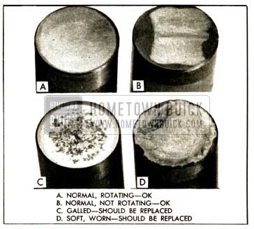
1952 Buick Lifter Body Wear Patterns
Replace the lifter assembly if this surface is excessively worn, galled, or otherwise damaged. Although lifters are slightly offset from the center of cam lobes to promote rotation, manufacturing tolerances may counteract this offset so that some lifters do not rotate. A non-rotating lifter body will have a square wear pattern on its lower end, with a very slight groove near the middle. Tests have proven that non-rotating lifters last as long and perform as well as rotating lifters, and the slight groove in the cam contact surface is not detrimental. Such lifters should not be replaced.
- Lifter Plunger. Using a magnifying glasses, inspect the check ball seat for defects. Inspect outer surface of plunger for scratches or scores. Small score marks with a rough, satiny finish will cause the plunger to seize when hot but operate normally when cool. Defects in check ball seat or scores or scratches on outer surface of plunger which may be felt with a fingernail are causes for replacing the lifter assembly. This rule does not apply to the slight edge which may sometimes be present where the lower end of plunger extends below the ground inner surface of the body. This edge is not detrimental unless it is sharp or burred.
A blackened appearance is not a defective condition. Sometimes the discoloration serves to highlight slight grinder chatter marks and give the outer surface of plunger a ridged or fluted appearance. This condition will not cause improper operation, therefore it may be disregarded.- Push Rod Seat. Replace the push rod seat if the area where the push rod contacts is rough or otherwise damaged. Make sure that oil hole is open.
- Check Ball. Using a magnifying glass, carefully examine the check ball for nicks, imbedded material or other defects which would prevent proper seating. Such defects would indicate the cause of intermittently noisy lifter operation. In some cases, diagnosis of improper lifter operation may be aided by checking the travel of the old ball with its retainer as described below (subpar. f). Even though no defects are found it is always advisable to discard the old ball and use a new one when reassembling the lifter.
- Ball Retainer. Replace a retainer which is cracked or which has a heavily pounded area between the two holes. A small bright spot where the ball contacts the retainer is the normal condition.
- Plunger Spring. Replace the plunger spring only if it is distorted or damaged. Exhaustive tests have shown that plunger springs seldom break down in service.
Check Ball Travel
It is very important to check the travel of the check ball and to bring it within prescribed limits before the lifter is assembled. Too much ball travel will allow excessive flow of oil from the lifter lower chamber just before the ball seats, causing excessive lash in the valve linkage. Insufficient ball travel will cause the volume of oil in the lower chamber to increase or “pump up”, thereby preventing the engine valve from seating.
- Prepare the ball travel checking attachment of Test Fixture J 5095 by using Sleeve KM0-30-K to mount Dial Indicator KM0-30-B so that stem of indicator bears squarely on upper end of the pin in attachment. See figure 2-18.
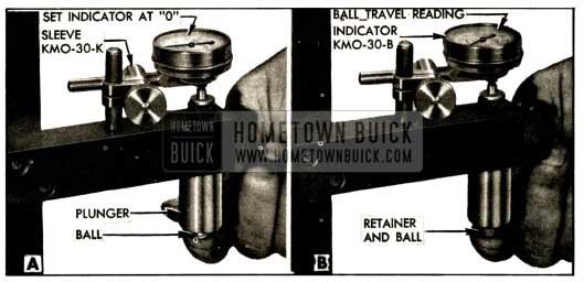
1952 Buick Checking Ball Travel
- Place a new check ball in the seat in lifter plunger, then hold plunger and ball firmly against the attachment arm with plunger centered over the pin and stepped flange. See figure 2-18, view A.
- While holding ball and plunger firmly in place, set the dial indicator needle at “0” (zero).
- Remove plunger and ball, place ball in ball retainer, and install these parts on plunger.
- Center the plunger over the pin and stepped flange of the check attachment and while pressing plunger and retainer firmly against attachment arm note the dial indicator reading. See figure 2-18, view B.
- The dial indicator reading shows the distance that the ball can travel from its seat until stopped by the retainer. The ball travel must be .004″ to .008″ to insure satisfactory lifter operation.
- If ball travel is not within the specified limits use another ball retainer (either used or new) and repeat steps 4 and 5. It may be necessary to try several retainers to select one that provides the required ball travel with the particular plunger and ball.
Assembly of 1952 Buick Hydraulic Lifters
All parts must be absolutely clean when a hydraulic lifter is assembled. Lint and dust may adhere to the parts if they are blown off or wiped with cloths; therefore they should be rinsed in CLEAN kerosene and assembled without drying.
- Rinse lifter body in the kerosene in middle compartment of cleaning tank and then give it a thorough final rinsing in the kerosene in right compartment.
- In the same manner, rinse the other parts one at a time and immediately place them in the body in the following order: spring, ball retainer, ball, and plunger. See figure 2-19. The plunger must slide freely into the body.
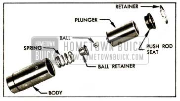
1952 Buick Hydraulic Valve Lifter Parts
- Rinse push rod seat and plunger retainer, place seat on plunger and depress these parts with Depressor J 5097 (fig. 2-14) while installing the plunger retainer in groove in lifter body.
- Wrap the lifter in clean paper or otherwise protect it from dirt while reconditioning the other valve lifters, preparatory to testing all lifters for leakdown rate.
Testing Lifter Leakdown Rate
After a hydraulic lifter has been cleaned, inspected, checked for ball travel, and assembled it must be tested for leakdown before it is installed in. an engine. Lifter Test Fixture J5095 has been” designed to test the leakdown rate of a lifter to determine whether it is within limits which assure satisfactory lifter operation. The following procedure must be carefully followed to obtain an accurate test.
- Prepare a special test fluid by placing 20 ounces of Special Buick Oil for Dynaflow Drive (Group 4.101) in a CLEAN and accurate one gallon container (glass jug), fill container to the one gallon mark with kerosene, then stir and shake the container to thoroughly mix the oil and kerosene.
- Thoroughly clean the cup of test fixture, make sure that the rubber disk is located in recess in bottom of cup, then install cup on fixture and fill it to within 1/2″ of the top with test fluid.
- Swing the weight arm up out of the way, raise the ram and place the valve lifter in cup of fluid, making sure that it seats squarely on the rubber disk in cup recess. The lifter must be completely covered by the fluid during test.
- Lower the ram to rest in the lifter push rod seat, then lower the weight arm to rest on the roller of ram as shown in figure 2-20.
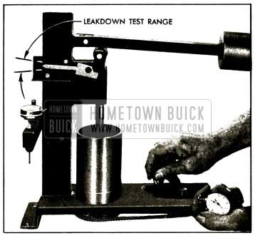
1952 Buick Checking Leakdown Rate
- Operate the lifter plunger through its full travel to force all air out of the lifter by using a vigorous pumping action on the weight arm. Continue the pumping action until considerable resistance is built up in the lifter and a definite grab point is felt at the top of the stroke, when the indicator pointer is at the bottom of the scale.
Finally, pump vigorougly for approximately 10 additional strokes to make sure all air is removed from the lifter. NOTE: If one stroke offers noticeable weak resistance during the last 10 pumping strokes replace the check ball in lifter and repeat the leakdown test to this point.
- Raise weight arm to allow the plunger to come up to its retainer, then lower the arm to rest on the ram roller. As the pointer starts moving upward start rotating the fluid cup by turning the handle one revolution every two seconds. See figure 2-20. The cup rotates the lifter body while the weighted ram hold he lifter plunger from turning, thus averaging, out any variations in clearance between these parts. NOTE: Check occasionally to make sure that lifter plunger is not turning.
- Use a stop watch to check the time required for the pointer to move from the lower to the upper mark on scale, which indicates the range in which the plunger normally operates in the body. The cup must be rotated during this test. See figure 2-20.
- The leakdown rate (time between marks) must be between 9 and 38 seconds to assure satisfactory lifter performance. A lifter should be tested three or four times. Replace any lifter which does not test within the specified limits.
- After all lifters have been tested, place the cover over the test fixture to keep dirt out of the cup and fluid. The fluid should be discarded and the cup should be thoroughly cleaned after a few sets of lifters have been tested.
Installation and Adjustment of Hydraulic Lifters
- Make sure that lifter guide holes and adjacent area of 1952 Buick cylinder block are clean, then oil and install valve lifters. Each lifter must slide freely in its guide hole; if a lifter is tight in one guide hole fit it to another hole.
- Install push rods and rocker arms (if – removed), engaging adjusting ball studs in push rod upper ends.
- For each 1952 Buick cylinder where valve lifters have been installed crank engine over slowly until the ignition distributor rotor is in position to fire the 1952 Buick cylinder. This places both valve lifters of the cylinder on the camshaft case circle (off the cam lobe) so that either lifter may be adjusted.
- Starting with some lash clearance in the valve linkage, turn the adjusting ball stud down until all play of push rod between lifter and ball stud is just removed and no lash clearance exists in the linkage.
- Turn ball stud down two complete turns to move the lifter plunger down and clear of its retainer. The oil groove on ball stud must be at least half way down in rocker arm so that it connects with oil passage in arm; if it is not, turn stud down one additional turn. Tighten lock nut. NOTE: If oil groove is still too high after 3 turns of ball stud it will be necessary to install another lifter or push rod.
- When it is necessary to adjust all valve lifters in an engine, time may be saved by aligning the “U.D.C. 1-8” mark on flywheel with index mark in timing hole in flywheel housing, first with No. 1 cylinder and later with No. 8 cylinder in firing position as indicated by position of distributor rotor. Adjust lifters according to the following table:
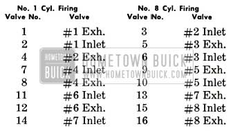
1952 Buick Hydraulic Lifter Adjustments
- Install push rod and rocker arm covers, then test for satisfactory lifter operation (par. 2-10).
2-16 REMOVAL AND INSTALLATION OF 1952 BUICK CYLINDER HEAD
CAUTION: On engines equipped with hydraulic valve lifters it is extremely important to avoid getting dirt into these units. When removing and installing cylinder head use every precaution to keep dirt out of the push rod compartment above the lifters.
Removal of 1952 Buick Cylinder Head and Gasket
- Drain cooling system and disconnect radiator thermostat housing from 1952 Buick cylinder head.
- Remove spark plug cover, disconnect wires from spark plugs and remove spark plugs.
- Disconnect temperature gauge tube and rocker arm oil pipe from cylinder head.
- Remove air cleaner and disconnect gasoline and vacuum pipes from carburetor and manifold.
- Disconnect rod from carburetor throttle lever. Disconnect return spring and equalizer shaft upper bracket from intake manifold.
- Disconnect exhaust pipe flange from exhaust manifold.
- Remove rocker arm cover then remove rocker arm, shaft, and bracket assembly. Lift out push rods. On some models it may be necessary to remove No. 16 push rod as cylinder head is removed.
- Slightly loosen all 1952 Buick cylinder head bolts, then remove bolts and lift off cylinder head with manifolds attached.
- For removal and installation of intake and exhaust manifolds, if desired, refer to paragraph 3-12.
Installation of 1952 Buick Cylinder Head and Gasket
Installation of 1952 Buick cylinder head and gasket is the reverse of removal procedure, with attention being given to the following instructions.
Before 1952 Buick cylinder head is installed, make certain that all dirt or carbon is blown out of the blind tapped bolt holes in cylinder crankcase so that bolts may be fully tightened without bottoming in holes. Examine gasket surfaces of 1952 Buick cylinder block and head for nicks or burrs and for ridges around bolt holes. Dress off all high metal spots with a good mill file.
Series 40 synchromesh engines use a Steelbestos cylinder head gasket .075 thick. Series 50 synchromesh and the Series 70 engines use a Steelbestos gasket .050″ thick.
Series 40-50 Dynaflow engines use a lacquered steel cylinder head gasket .015″ thick. Use care when handling this gasket to prevent damage to the lacquered surface coat and to prevent kinking at the sealing rings stamped in gasket. The lacquered gasket should not be coated with any type of sealing material when installed. Always use a new steel gasket because the stamped sealing rings are flattened in a used gasket.
1952 Buick cylinder head bolt holes on manifold (left) side are open to water jacket; therefore bolts installed on this side should have threads coated with sealing compound to avoid water leaks.
On Series 40 synchromesh engines (with adjustable valve lash) a baffle is attached by No. 1 rocker arm shaft bracket bolt and the oil inlet pipe extends down through a small hole in baffle.
Always use an accurate torque wrench when tightening 1952 Buick cylinder head bolts, to insure uniform and proper torque on all bolts. Uneven or excessively tightened bolts may distort cylinder bores, causing compression loss and excessive oil consumption. A 3/4″ Wrench Attachment KMO 187-1 should be used with the torque wrench to properly tighten bolts located under the valve mechanism. See figure 2-21.
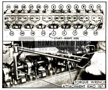
1952 Buick Tightening Cylinder Head Bolts
Tighten cylinder head bolts to 65-70 ft. lbs. torque following the sequence shown in figure 2-21. After installation of cylinder head, particularly with the crimped steel gasket, tighten all bolts a little at a time in proper sequence about three times around before final tightening to 65-70 ft. lbs. torque. After the engine has been warmed up to operating temperature, recheck bolts and adjust torque as required.
Adjust valve lash (par. 2-14) or make initial adjustment of hydraulic valve lifters (par. 2-15, i).
Replacement of 1952 Buick Rocker Arm Cover Gasket
Before a new gasket is installed, scrape off all pieces of old gasket from 1952 Buick cylinder head, wash machined surface with suitable solvent and wipe it dry.
The valve rocker arm cover gasket should be cemented to the cylinder head instead of the cover. When gasket is cemented to the cover it is more easily damaged when removing or installing cover.
Apply a heavy coat of thick gasket shellac or cement to gasket surface of 1952 Buick cylinder head, allow it to dry until quite tacky, then press gasket down evenly and in proper position on cylinder head. Install rocker arm cover to hold gasket in place until cement is thoroughly dry.
2-17 RECONDITIONING VALVES
Cleaning, Refacing and Reseating Valves
After removal of valves and springs from 1952 Buick cylinder head, scrape all carbon from combustion chambers and valves. If wire brushes are used for cleaning carbon, use care to avoid scratching valve seats and valve faces. Clean all carbon and gum deposits from valve guides.
Valve faces and valve seats must not be cut away excessively when using refacing and reseating equipment. Only enough metal should be removed to true up the surfaces and remove pits.
The valve head will run hotter as its thickness is decreased. If valve head must be ground until the outer edge is sharp in order to clean up the face, the valve should be discarded because the sharp edge will run too hot.
Cutting a valve seat results in lowering the valve spring pressure and increases the width of the seat. The nominal width of a valve seat is .062″ (1/16″). If valve seat is over 5/64” wide after truing, it should be narrowed by using the proper 20 degree and 70 degree cutters.
The refacing and reseating operations should leave the refinished surfaces smooth and true so that a minimum of lapping with grinding compound is required. Excessive lapping will groove the valve face and a grooved valve will not seat tightly.
Valves usually are tested after refacing and seating by lightly coating the valve face with prussian blue and turning the valve against its seat. This indicates whether the seat is concentric with the valve guide but does not prove that valve face is concentric with the valve stem, or that the valve is seating all the way around. After making this test, wash all blue from surfaces, lightly coat valve seat with blue and repeat the test to see whether a full mark is obtained on the valve. Both tests are necessary to prove that a proper seat is being obtained.
Replacement of Valve Stem Guides
If valve stem guides are worn to the extent that replacement is necessary, drive old guides out with Remover and Replacer J 269. When a new guide is driven into place from top side of cylinder head the upper end of guide must extend 1%2″ above the top surface of 1952 Buick cylinder head.
Replacement guides must be finish reamed after installation in 1952 Buick cylinder head. Use Valve Guide Reamer J 129-3 to provide .374″ to .375″ finished size in both inlet and exhaust guides.
The clearance between inlet valve stem and guide is .0015″ to .0035″ (.0025″ desired). The clearance between exhaust valve stem and guide is .0021″ to .0039″ (.003″ desired). The inlet and exhaust valve stems are ground to proper diameters to provide the different clearances in guides of the same reamed size.
After valve guides have been reamed to size, true up valve seats so they are concentric with guides and test for proper seating of valves (subpar. a, above).
Correct Assembly of Rocker Arms, Springs, Brackets and Shaft
The rocker arms are mounted on a tubular steel shaft which is supported upon the 1952 Buick cylinder head by eight brackets attached by bolts and studs. Springs placed around the shaft between adjacent rocker arms hold the arms in position against the brackets. The rocker arm at each end of shaft is held against the bracket by two flat washers with a spring washer between, and a cotter pin. The shaft is prevented from turning by a pilot screw in the second bracket. See figure 2-22.
1952 Buick Rocker Arms, Shaft and Brackets
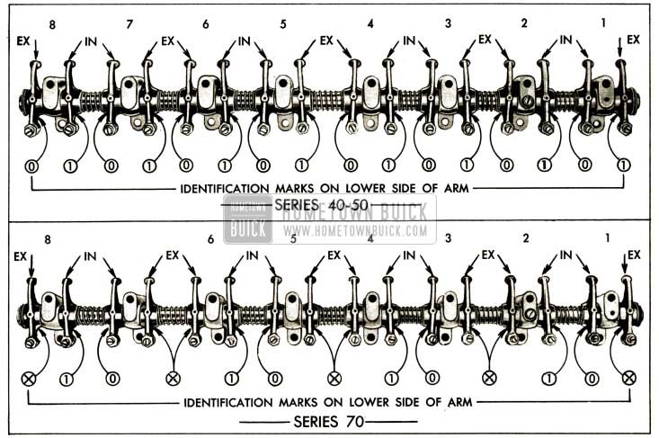
Two different valve rocker arms are used on each Series 40-50 engine, differing only in the angle at which the arms extend from the shaft. Both rocker arms are offset, meaning that arms extend at an angle other than 90 degrees to centerline of shaft. Two different offset rocker arms are used for inlet valves on Series 70 engines, and a third straight (90 deg.) rocker arm is used for all exhaust valves.
To identify each rocker arm and assist in installation, an identification mark is formed in the lower side of bearing boss, and identification depressions or dots, or a number, also are formed in upper side of bearing boss as follows:

1952 Buick Vavle Identification Overview
2-18 CHECKING VALVE AND CAMSHAFT TIMING
A 1952 Buick timing chain will usually become noticeably noisy at idle speed before it has worn to the extent that valve timing is changed enough to noticeably affect engine performance. When it becomes desirable to check valve timing to determine whether the chain has been correctly installed, it may be done in the following manner.
Checking Timing on Engine Having Adjustable Valve Lash
- Adjust valves for .015″ road operating lash (par. 2-14), stop engine and turn until either No. 2 or No. 7 exhaust valve is fully closed.
- Mounting dial indicator to bear against the valve spring cap of the fully closed exhaust valve and set indicator at zero. See figure 2-23.
1952 Buick Dial Indicator Set to Check Valve Timing
- Slowly turn engine in running direction only until exhaust valve opens exactly .145″.
NOTE: It is advisable to remove flywheel lower housing so that engine can be turned very slowly by means of pinch bar applied to flywheel ring gear.
- Remove timing hole cover. If the “U.D.C. 1-8” mark on flywheel is visible through the timing hole, the valve and camshaft timing is correct.
Checking Timing on 1952 Buick Engine Having Hydraulic Valve Lifters
- Turn engine until either No. 2 or No. 7 exhaust valve is fully closed.
- Mount dial indicator to bear against the valve spring cap of the fully closed exhaust valve and set indicator at zero. See figure 2-23.
- Loosen adjusting ball stud lock nut and tighten adjusting ball stud until indicator momentarily reads .015″, then wait until leak down in valve lifter allows indicator to return to zero.
- Repeat Step 3 until indicator fails to return to zero, indicating that valve lifter plunger is bottoming on shoulder in lifter body. While observing indicator, carefully loosen ball stud just enough to obtain zero indicator reading.
- On Series 40-50 engine, slowly turn engine in running direction only until exhaust valve opens exactly .145″. On Series 70 engine, open exhaust valve exactly .155″. NOTE: It is advisable to remove flywheel lower housing so that engine can be turned very slowly by means of pinch bar applied to flywheel ring gear.
- Remove timing hole cover. If the “U.D.C. 1-8” mark on flywheel is visible through the timing hole, the valve and camshaft timing is correct.
- After checking timing readjust ball stud and valve lifter as described in paragraph 2-15.
2-19 REPLACEMENT OF 1952 BUICK TIMING CHAIN AND CRANKSHAFT OIL SEAL
Replacement of 1952 Buick Timing Chain
- Drain cooling system and remove 1952 Buick radiator core.
- Remove fan belt and crankshaft balancer.
- Remove timing gear cover after loosening two lower crankcase bolts on each side to avoid damage to gasket.
- Check the slack in timing chain. Initial slack in the timing chain when new allows 1/4″ to 3/4″ outward movement under finger pressure applied midway between points of contact with sprockets. Permissible slack in a worn chain can be as high as 1″ outward before it is necessary to replace the chain.
- If chain requires replacement, turn crankshaft to align timing marks on sprockets with timing marks on chain. Each sprocket has a punch mark at one space between two teeth. Two teeth on timing chain, ten links apart, are marked with copper plated washers. See figure 2-24.
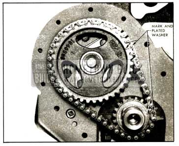
1952 Buick Timing Chain and Sprocket Marks
- Remove camshaft sprocket which is attached to camshaft by a bolt, lockwasher and plain washer. The sprocket drives camshaft through a key pressed into camshaft. Remove timing chain as sprocket is removed.
- Thoroughly clean all sludge from timing gear cover and timing chain compartment. Make sure that oil drain hole to lower crankcase is clear.
- Install new timing chain with camshaft sprocket, being sure that timing marks on sprockets and chain are in line as shown in figure 2-24.
- Examine crankshaft oil seal in timing gear cover. If seal is worn or of doubtful condition install a new seal as described in subparagraph b below.
- Before installation of timing gear cover, coat rubber lip of oil seal with Standard Graphite Grease No. 4. When cover is installed make sure that the two dowel pins are in place in crankcase to properly locate cover so that the oil seal will be centered around the hub of crankshaft balancer.
- Use care when installing crankshaft balancer to avoid damage to crankshaft oil seal. Complete the installation of parts and adjust fan belt tension (par. 2-27).
Replacement of 1952 Buick Crankshaft Oil Seal
The 1952 Buick crankshaft oil seal is pressed into a recess in timing gear cover and a gasket is used to prevent leakage around the seal. See figure 2-25.
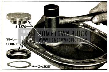
1952 Buick Crankshaft Oil Seal and Gasket Installation
- Drive old seal out with a punch, using care not to distort timing gear cover. Remove old gasket and wipe all dirt out of recess.
- Place a new gasket in recess, and place new oil seal in position over recess, with the spring side outward.
- Drive oil seal into recess and tight against the gasket, using Oil Seal Driver J 1870. See figure 2-25.
- Examine hub of crankshaft balancer for burrs which would damage the oil seal and for grooving from contact with oil seal. If hub is grooved, oil leakage may be expected even with a new seal. A slightly grooved hub may be refinished; however, if deeply grooved the balancer should be replaced to insure proper contact of hub with oil seal.
2-20 1952 BUICK CAMSHAFT BEARINGS AND END PLAY
The 1952 Buick camshaft is supported in five steel-backed babbitt-lined bearings which are pressed into the cylinder crankcase. The camshaft bearings must be line reamed to size after being pressed into the crankcase. Since this operation requires special reaming equipment the original bearings should be retained unless severely damaged.
Slightly scored camshaft bearings will be satisfactory if the surface of camshaft journals are polished and bearings are cleaned up to remove burrs, and the fit of shaft in bearings is free and within the clearance limits of .0015″ to .004″.
Camshaft end play is controlled by a spacing ring located between the camshaft front bearing journal and a thrust plate attached to crankcase behind the camshaft sprocket. The spacing ring provides clearance or end play of .004″ to .009″ when the camshaft sprocket is tightened against it by the sprocket bolt.
IMPORTANT. When a new camshaft is installed make certain that it is the correct part for the type of valve mechanism in the engine. Use of a camshaft designed for plain sleeve lifters in an engine equipped with hydraulic valve lifters, or vice-versa, will result in extremely rough and noisy engine operation.
For identification purposes, camshafts have a 1/4″ land located between No. 6 and No. 7 valve operating cams. This land, which may be seen when lower crankcase is removed, is finished as follows:
- For Plain Sleeve Lifters-land has dark, rough-turned surface, with a 1/16″ x 1/16″ groove cut in center.
- For Hydraulic Lifters-land has a bright finish ground surface and no groove.
Leave A Comment
You must be logged in to post a comment.