SECTION 13-B 1952 BUICK DOORS AND COMPARTMENT LIDS
13-5 1952 BUICK DOOR LOCKS AND HANDLES
Description of 1952 Buick Door Locks and Handles
Each 1952 Buick door lock is operated by a push button in the stationary outside handle and also by an inside handle and remote control assembly which is connected to the lock by a link. The connecting link has slotted holes to permit operation of lock by either the outside push button or the inside handle.
All 1952 Buick doors may be locked from the inside by pushing down the locking knob which projects through the garnish molding. All 1952 Buick doors may be locked from the outside by first pushing down the inside locking knob then holding the outside push button depressed while closing the door.
1952 Buick rear doors cannot be unlocked from outside the car. Both front doors can be unlocked from outside by inserting key in the safety lock incorporated in the outside handle push button. The outside safety locks are operated by the same key that operates the ignition switch, glove box door lock and rear compartment lid lock.
A “free-wheeling” linkage incorporated in the rear door locks permit adjustment so that the doors cannot be opened by operating the inside handle when the locking rod knob is down. This safety feature, desirable where small children ride on the back seat, prevents accidental opening of a rear door when the car is in motion. Locks are set for “free-wheeling” at the factory and must be reset for positive operation at the request of car owner.
The 1952 Buick door lock is the lift bolt type. As the door is closed the lock bolt enters the upper guide channel of door lock striker and is forced upward until the locking mechanism is engaged at the top of bolt travel. When the locking mechanism is tripped to unlock the door, the bolt is forced downward and out of the striker. A dovetail wedge mounted on the lock engages the lower channel in the door lock striker. A spring loaded bumper is mounted in upper side of the dovetail wedge channel.
Free Wheeling Adjustment – 1952 Buick Rear Door Locks
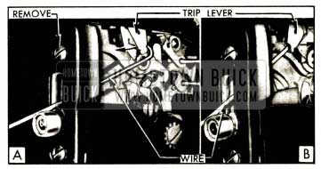
To change rear door locks from “free-wheeling” to positive operation, or vice versa, prepare a 7″ length of stiff wire approximately 1/8″ in diameter with a right angle hook 3/8″ long on one end.
Remove the lock attaching screw just above the bolt slot in lock pillar so that the free wheeling trip lever can be sighted through the screw hole. Light from a small flashlight can be admitted through the bolt slot to aid in locating the trip lever.
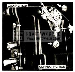
To change lock from free wheeling to positive operation, insert hook end of wire through bolt slot and pull outward on free wheeling trip lever. See figure 13-3, view A. To change lock from positive operation to free wheeling, place hook against near side of trip lever and push lever inward. See figure 13-3, view B.
1952 Buick Free Wheeling Adjustments
1952 Buick Door Lock Striker Adjustment
The 1952 Buick door lock striker may be adjusted in or out, up or down, by loosening the striker attaching screws. Serrations on the back of striker and on the body pillar, coupled with a floating anchor plate in body pillar, allow for these adjustments.
Before removing the 1952 Buick door lock striker or making an adjustment it is advisable to mark its position on body pillar with a pencil. This will permit it to be reinstalled in the same position, or will aid in gauging the amount of adjustment.
The 1952 Buick door lock striker should be adjusted in or out to secure good contact of 1952 Buick door weatherstrip with body and to permit positive locking of door lock bolt. The striker should be vertically adjusted so that the dovetail wedge and the lock bolt enter centrally into the guide channels of striker. The dovetail wedge and striker should support the lock side of door without upward or downward strain. Long vertical serrations keep the striker at the proper angle to insure proper contact with dovetail wedge when the vertical adjustment is correctly made.
When correct engagement between the 1952 Buick door lock lift bolt and the striker cannot be obtained, close the door and carefully roll back the wind hose to check the spacing between the striker and the door lock pillar, using a suitable gauge. If the spacing exceeds 19/64″, install a door lock striker spacer (Group 10.571) as shown in figure 13-4.
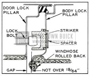
1952 Buick Door Lock Striker Spacer Installation
Be sure to use the longer striker screws listed in Group 10.571 to insure safe anchorage of the striker and spacer.
1952 Buick Door Outside Handle or Safety Lock Replacement
- On Series 50-70, release the door rubber weatherstrip from lock pillar face adjacent to handle. Some front doors have a weatherstrip support at this point which must also be removed. Remove screw holding the handle retainer to lock pillar face.
- On all series, pull out the flat spring handle retainer until handle can be removed. See figure 13-5.
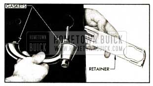
1952 Buick Removal of Retainer and Door Handle
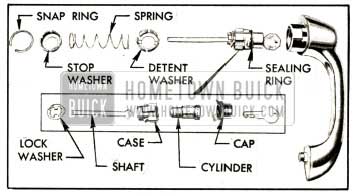
1952 Buick Handle and Outside Safety Lock Disassembled
In some cases it may be necessary to install a new longer push button shaft in order to properly trip the lock bolt when the push button is depressed. When a new shaft is installed it must be checked and cut to proper length as described in the following steps.
- Hold the 1952 Buick door handle in its normal position on door and carefully guide the push button shaft into the lock. Raise the lock lift bolt until it latches in upper position then depress the push button while holding handle rigidly in place. If the lift bolt snaps down, the shaft is correctly located in the lock.
- Still holding the handle in its normal position on door and so that the shaft is just contacting the lock trip lever, measure the di3tance between the door outer panel and the near edge of lock handle. See figure 13-7.
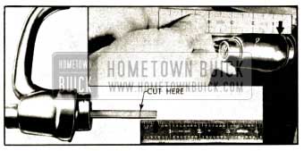
1952 Buick Measuring and Cutting Push Button Shaft
1952 Buick Door Lock Replacement
- Remove 1952 Buick door outside handle (subpar. d, above), door trim pad (par. 13-19) and remove inspection hole cover from door inner panel below the lock.
- Disconnect the door lock remote control connecting rod from lock by removing the remote control mechanism.
- Remove inside locking rod. To remove locking rod on rear doors remove the single bolt and washer holding the inside locking rod lever to the door inner panel.
- On Series 40, remove the glass run channel retaining screw through inspection hole. On Series .50-70 front door, or rear door without ventilator or stationary glass, remove the glass run channel retaining screw on lower outer face of 1952 Buick door lock pillar.
- Remove lock attaching screws and lockwashers-two on door inner panel and three on lock pillar facing. See figure 13-8.
1952 Buick Door Lock Attaching Screws
Make sure deflector is securely cemented before installation of lock.
Before installing lock make sure that bolt is in “down” position. On front doors the U-shaped retainer on lock housing must be threaded behind the lower end of glass run channel during installation. This can be done by slightly pulling out lower end of channel. Seal the inspection hole cover before installing it on door inner panel.
When installing 1952 Buick door lock remote control, attach it to door inner panel so that there is no end play in the connecting rod. Slotted screw holes permit this adjustment.
13-6 1952 BUICK DOOR AND REAR COMPARTMENT LID WEATHERSTRIPS
Description of 1952 Buick Weatherstrips
Molded rubber weather strips in several pieces are cemented to the flanged edges of each 1952 Buick door. A sheet metal retainer attached to the door gives support to the weatherstrip along bottom edge of door. The retainer has a scalloped flange which is crimped over the base of weatherstrip after it is cemented in place. On rear doors, the 1952 Buick weatherstrip is cemented to the face of door hinge pillar and is also supported by a sheet metal retainer attached to hinge pillar with screws.
On each Series 50-70 front door, a bellows type sealing strip is cemented to the cowl and to front surface of door hinge pillar in such position that it is not affected by the swinging movement of door.
On Riviera and Convertible bodies, the rear and top edges of the door window glasses bear against weatherstrips mounted on the rear quarter windows and the roof side rails. On Series 50-70 Riviera bodies a mechanical “flipper” type roof side rail sealing strip assembly is used above the door windows, as described in paragraph 13-15.
The rear compartment lid is sealed by a molded rubber weatherstrip cemented along the bottom and sides of the lid flange and another molded rubber weatherstrip cemented into the gutter along the top and upper corners of the body opening. Each end of the gutter weatherstrip is also secured by a retainer and screw.
Checking Contact of Weatherstrips
To avoid dust and water leaking through door or compartment lid openings, the weatherstrip must be in good condition and securely cemented to the metal surface on which it is mounted. The lip of the weatherstrip must make firm contact at all points. This can be checked by closing the door or lid on a slip of paper placed at intervals around the opening. If paper can be withdrawn, an adjustment of the door or lid may be necessary.
Moving the door or lid inward for closer contact of rubber weatherstrip may be accomplished by lock striker or hinge adjustment. If door or lid is in proper alignment in body opening, however, correction of air or water leak will probably require correction of rubber weatherstrip condition. If weatherstrip is loose or distorted it should be loosened sufficiently to permit proper adjustment and recementing. If damaged or deteriorated the weatherstrip should be replaced.
Cementing Weatherstrips
When re-cementing or replacing a rubber weatherstrip the following procedure must be used to insure permanent adhesion.
- Carefully remove old weatherstrip or portion to be re-cemented.
- If the weatherstrip was attached with the original factory adhesive which has a neutral color, clean the adhesive from metal surface with a putty knife or a dry rag. It is not necessary to remove this adhesive from the weatherstrip. Do not use solvents (oleum spirits, gasoline, etc.) to clean off this type of adhesive.
- If the weatherstrip has been previously reset with the black adhesives used in service, it may be necessary to use oleum spirits or a similar solvent to clean off the old adhesive.
- Allow surfaces to dry, then brush a coating of 3-M Weatherstrip Adhesive on mating surfaces of metal and weatherstrip.
- Keep coated parts separated and allow cement to air dry until “tacky,” which requires about 15 minutes. If parts are joined when cement is wet the weatherstrip will not adhere properly.
- Press weatherstrip firmly into place, being careful not to stretch it. When attaching weatherstrip along bottom of door be careful not to close drain holes in door inner panel.
- After weatherstrip is attached along bottom of a door crimp the scalloped flange of retainer over the base of weatherstrip. On a rear door, attach weatherstrip retainer to door hinge pillar with screws.
IMPORTANT: Do not close the door or lid for at least a half hour after re-cementing or installation of weatherstrip. If time permits, leave open for a longer period. If door or lid is closed before cement is thoroughly dry, the pressure against lip of weatherstrip may cause weatherstrip to pull away from its cemented base and early failure of the installation may result.
Replacement of 1952 Buick Series 50-70 Front Body Hinge Pillar Sealing Strip
If only the upper end of sealing strip is damaged in the area above the upper door hinge, repairs may be made with a patch strip which is available for service. This patch strip should be installed in the same manner as the upper end of a full strip, should overlap the lower portion at least one inch on the forward side and should be securely cemented to lower portion where it overlaps.
If sealing strip is damaged below the upper door hinge a complete new strip should be installed as follows:
- Carefully loosen the broad end of door rubber weatherstrip that is cemented over the upper end of sealing strip.
- Remove the door stop and all metal fasteners that attach the sealing strip to door and cowl, then remove the sealing strip.
- Clean off all old adhesive from door and cowl where sealing strip was attached.
- Use 3-M Weatherstrip Adhesive to cement the new sealing strip to the front face of door hinge pillar. In this operation insert the fastener stud on lower end of hinge pillar through the hole in the sealing strip to insure proper vertical position of strip. See figure 13-9, view C.
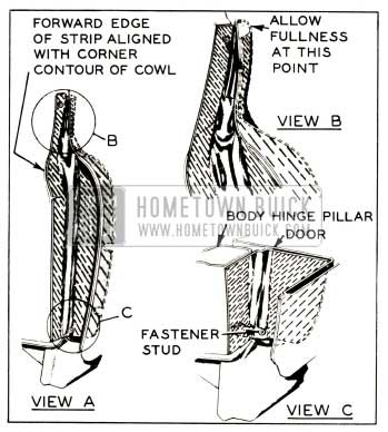
1952 Buick Hinge Pillar Sealing Strip Installation
13-7 1952 BUICK DOOR ALIGNMENT; ADJUSTMENT OF DOOR HINGES AND CHECK LINKS
Checking Door Fit in Body Opening
A 1952 Buick door which is hard to open and close or which does not fit the door opening in body with even spacing all around and close flush with adjacent body panels should be carefully checked for fit in body opening before attempting any adjustment of hinges or door lock striker. Sometimes a combination of adjustments are required and time will be saved by checking as follows:
- Check for even contact of door rubber weatherstrip with body by closing door on a slip of paper placed at intervals around door. If paper can be withdrawn an adjustment of the door hinges, door lock striker or weatherstrip is indicated.
- Remove door lock striker to allow door to hang free on hinges without support from the dovetail wedge on door lock.
- Close the door and check the spacing of door in body opening at front, top and rear edges. The spacing should be uniform in width along each edge and should be approximately equal at all three edges.
- Check the belt molding or horizontal crease line at belt line of door and body. This should be in continuous alignment along the side of body from front edge of front door through the rear quarter panel.
- Hold door closed and check door flanges for being flush and in uniform alignment with adjacent body panels.
Careful consideration of door spacing, belt molding or crease line alignment, weatherstrip contact and door flange alignment will show whether correction can be made by adjustment of door lock striker or door hinges or a combination of both. It also will show whether the door or door opening requires truing up by other means than adjustment.
If hood is not in proper alignment with front doors, the hood should be adjusted; do not attempt to shift a properly fitting door to obtain alignment with the hood. Likewise, if door fits body opening properly, the fender rather than the door should be adjusted, if required, to secure proper alignment and clearance of these parts.
General Instructions for Adjusting 1952 Buick Door Hinges and Lock Strikers
The following general instructions apply to all 1952 Buick doors. For specific instructions on adjustment of 1952 Buick door hinges see subparagraph c.
Adjustment and fitting of a door in body opening should always start at the hinge side of door, with door lock striker removed to allow door to hang free on hinges.
Before making an adjustment at the hinges it is advisable to mark the location of hinge on body and door so that amount and direction of hinge movement can be measured as an aid in adjustment.
1952 Buick doors are heavy and hard to handle if all hinges are loosened during door adjustment and it may require the services of two men, one to hold the door at the correct adjustment while the other man tightens the hinge.
The in and out, or fore and aft adjustment may be simplified if only one door hinge at a time is loosened, adjusted and then tightened again.
To facilitate easy adjustment of the door up or down, use a car jack placed under the center of the door when it is in an open position. When the hinge screws are loosened, the jack may be operated to move the door up or down to the correct adjustment with very little effort, after which the screws may be tightened again.
In some cases it may be necessary to use a combination of vertical, in-and-out and fore-and-aft adjustments to secure proper fitting of door in body opening and proper contact of door weatherstrip with body.
Alignment of door and body belt moldings or crease lines at hinge pillar should be obtained first, by vertical adjustment of door at hinges. Then align door flange so that it is flush with adjacent hinge pillar by an in or out adjustment of one or both hinges. Finally, obtain spacing of uniform width along hinge side which is approximately equal to spacing on lock side of door by fore or aft adjustment of one or both hinges.
When door is properly adjusted at hinge side, uniform spacing and also alignment of belt moldings or crease lines should exist at the lock side of door. In order to obtain alignment of moldings or crease lines at lock edge of door it may be necessary, in some cases, to adjust hinges so that door spacing on hinge side is not exactly uniform in width; however, the spacing must not be noticeably tapered on either the front, top or rear edges of door.
After door hinges have been adjusted for proper fit of door in body opening install and adjust the door lock striker as described in paragraph 13-5 (c).
1952 Buick Door Adjustment at Hinges
On 1952 Buick Series 40 front doors, up, down, in, and out adjustment at hinges is provided through floating hinge bolt anchor nuts mounted in front body hinge pillar. Hinge bolts are accessible with door opened. Forward and rearward adjustment, together with a slight up and down adjustment, is provided by the slotted bolt holes in hinge gooseneck strap where strap is bolted to door. It is necessary to release the door trim pad to reach these bolts.
On 1952 Buick Series 50-70 front doors, slotted hinge bolt holes and floating anchor nuts in the front body hinge pillar provide up and down adjustment. In and out adjustment is provided by slotted holes and floating anchor nuts in door hinge pillar. All hinge bolts, except on door end of lower hinge, are accessible with door opened and hinge cover plates removed.
The attaching bolts for door end of the Series 50-70 front door lower hinge are covered by the sealing strip cemented to door pillar. To reach these screws, raise hood and work through the space between fender and cowl in front of door. Pry off the circular disc clip retaining the lower end of sealing strip to snap fastener stud on door pillar, then carefully loosen lower end of sealing strip to uncover hinge screws. After hinge adjustment recement sealing strip; first attach strip to fastener stud with a new disc clip and then press cemented area of strip to door pillar. Install metal retainer which secures sealing strip to door.
Forward and rearward adjustment of Series 50-70 front doors is not provided since this adjustment should not be required unless the hinges or door have been distorted by an accident. A bent hinge should be removed and straightened or replaced.
On all series rear doors, slotted hinge bolt holes and floating anchor nuts in the door hinge pillar provided up and down adjustment. In and out adjustment is provided by slotted holes and floating anchor nuts in the body hinge pillar. All hinge bolts are accessible with door opened and hinge cover plates removed. On Series 50-70 doors it is necessary to loosen the weatherstrip and its retainer from the hinge area. See figure 13-10.
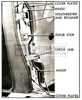
1952 Buick Rear Door Hinges, Cover Plates, and Weatherstrip Series 50-70
A slight rearward movement of a rear door may be obtained by placing a thin full-width waterproof cardboard shim between the hinge strap and body hinge pillar. Greater movement may be obtained, if necessary, by placing a narrow shim between the outer edge of hinge strap and body pillar to tilt the hinge and move door rearward.
To move a rear door forward, place a narrow waterproof cardboard shim between the inner edge of hinge strap and body pillar to tilt the hinge and move door forward.
When 1952 Buick door hinge adjustments are completed be sure to reinstall all hinge cover plates. Before installation on rear doors, fill the hinge depression at top and bottom of hinge strap with 3-M Autobody Sealer in the areas covered by the plates, also brush sealer on inner surfaces of cover plates. It is important to have joints around hinges water tight. Re-cement weatherstrips and sealing strips where these have been loosened, and attach rear door weatherstrip retainers with screws.
After a door has been readjusted at the hinges, the sill plate and door lower weatherstrip should be checked for proper contact. The sill plate may be adjusted “in” or “out” by relocating the plate attaching screw holes in body. Where necessary, the door weatherstrip may be shimmed to improve the contact along bottom of door opening.
1952 Buick Front Door Check and Hold-Open Devices
On Series 40 front doors, flat steel springs are mounted in the upper and lower hinges to provide check and hold-open devices. Each spring contains a channel which engages the gooseneck strap of hinge when door is fully opened, thereby limiting door opening and holding door in opened position. First production jobs are provided with a check link similar to the rear door check link (subpar. e) and hold-open springs are not mounted in the hinges.
On Series 50-70 front doors, a check link is used which contains a pair of springs for counterbalancing the door to hold it open, while the toggle action of the links establishes a definite hold-open position. The check link is not adjustable except for its position on door inner panel. The bolt holes in door inner panel are slotted to permit proper location of check link so that it will operate without binding. A separate non-adjustable stop mounted on the front face of door hinge pillar provides a definite wide-open stop for the door.
1952 Buick Rear Door Check Links
The rear door check link device consists of a flat spring steel link anchored to the center body pillar and a roller support mounted in the door hinge pillar. The hooked rear of the link engages the roller on the support to limit the door opening and also to provide a hold-open stop. See figure 13-10.
The check link support attaching screw holes are slotted so that support can be moved laterally to increase or decrease the hold open force. If proper hold open force cannot be secured by this adjustment, a shim may be placed between the link and center body pillar at point of attachment. If door does not stay in hold-open position place shim to rear of bolt and in line with end of the spring washer on link strap. If door snaps shut, place shim forward of bolt and in line with end of check link strap.
On Series 50-70, an adjustable door stop is mounted on the door hinge pillar about midway between the hinges. This stop is a wedge shaped plate that can be moved in or out to adjust for fully opened position of door. See figure 13-10.
13-8 1952 BUICK REAR COMPARTMENT LID, HINGE, AND LOCK ADJUSTMENTS
Description of Hinges and Lock
The 1952 Buick rear compartment lid is attached to the body by two concealed hinges. The strap portion of each hinge is attached to the inner panel of lid by bolts and floating anchor plates which permit adjustment of the lid in the body opening.
In some bodies, each compartment lid hinge contains a heavy coil spring for counterbalancing the lid and holding it in the fully opened position. In other bodies, the counterbalancing and hold open features are accomplished by torque rods which are attached between the hinges and the body.
The 1952 Buick compartment lid is unlocked by the ignition key. When key is inserted in lock and turned clockwise the lock snaps the lid into an unlocked position from .which it can be easily raised. The lid is locked by simply pushing it down-the lock automatically snaps into locked position. The key is not used when locking the lid.
The lid lock striker is mounted at lower edge of body opening in position to be engaged by the lock on compartment lid. Slotted bolt holes in striker permit adjustment to provide positive locking and proper pressure of lid against the weatherstrip.
Lid, Hinge and Lock Striker Adjustments
Adjustment of 1952 Buick rear compartment lid, hinges, and lock striker is required whenever an edge of lid is noticeably out of alignment with adjacent body panels, upper edge of lid contacts shoulder of body rear panel when lid is opened, or lid does not lock properly. Adjustment also may be required to correct dust or water leaks provided the weatherstrip is in good condition and securely cemented in place.
Before making any adjustment examine the fit of rear compartment lid in the body opening. The spacing along the top, bottom, and sides should be approximately equal and spacing along top edge of lid must be sufficient to prevent contact with shoulder on body panel when lid is raised. The edge of compartment lid should be fairly flush with adjacent body panels all around.
If spacing is objectionably unequal adjustment may be made by loosening hinge strap attaching screws and shifting lid in direction required. In some models a dowel pin mounted on lid engages a hole in a pilot bracket welded to body adjacent to lock striker. It may be necessary to shift the position of the dowel pin to obtain the required movement of compartment lid.
The spacing along top edge of lid may be correct but the lid contacts shoulder of body panel when lid is raised; this is because the hinge side of lid is set too low. On the other hand, the upper edge of lid may stand away from the body panel because it is set too high. Either condition may be corrected by shims placed between lid and hinge strap on side requiring adjustment. To raise edge of lid at either hinge, place a shim of proper thickness between lid and the forward end of hinge strap. To lower edge of lid, place shim at rear end of hinge strap.
After the hinge side of compartment lid is properly aligned, the lower or lock side of lid may be adjusted for alignment with body rear end panel and proper contact with weatherstrip by adjusting the lock striker up or down as required. Some models have adjustable rubber bumpers on each side to steady the lid near the lower corners. These should be adjusted to contact underside of lid when closed, but not so that lid cannot contact the weatherstrip.
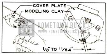
The striker must not be set so low that the lock cannot snap into a securely locked position when lid is pressed down. To check the amount of engagement of the lid lock bolt with the striker, press a small wad of modeling clay into inner end of lock bolt slot, then close lid with a moderate slam. Open lid and check thickness of clay remaining in the slot; this should be 1/8″ to 11/64″. See figure 13-11. If proper lock bolt engagement cannot be obtained by adjustment of striker, insert a spacer under striker to get the desired engagement.
1952 Buick Checking lock Bolt Engagement With Striker
Replacement of 1952 Buick Rear Compartment Lid Lock Cylinder or Lock
The lock cylinder is retained by a flat steel retainer on inner side of the lid outer panel. To remove lock cylinder, reach through access hole in lid inner panel and pull forward on upturned end of the retainer to disengage it from the cylinder. When lock cylinder is installed by reversing removal procedure be sure to cement the gasket which is placed between lid panel and the outer flange of lock cylinder.
To remove the rear compartment lid lock assembly, remove lock screw, the four lock and cover plate screws, and the cover plate shown in figure 13-11. Lock assembly can then be removed from lid inner panel.
Replacement of 1952 Buick Rear Compartment Lid Hinge-Coli Spring Type
If it becomes necessary to remove a coil spring type lid hinge, protect body panel with suitable cover and provide a support for lid on side where hinge is to be removed. Scribe hinge strap location on lid inner panel then remove hinge strap attaching screws. Bend up the retaining tabs and remove the two hinge pins which extend through the hinge box.
When hinge is reinstalled be sure to place gasket between hinge strap and compartment lid inner panel. Adjust hinge to align compartment lid in body opening (subpar. b, above).
Replacement of 1952 Buick Rear Compartment Lid Hinge-Torsion Rod Type
- Open the rear compartment lid and brace it safely before attempting any work on the torque rods.
- Remove the screw and clip which attaches outer angle of torque rod to body.
- Place a short length of pipe over outer end of torque rod and lift the rod up and toward center of body to release it from the bracket. See figure 13-12.
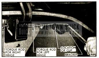
1952 Buick Removing Hinge Torque Rod
13-9 1952 BUICK INSTRUMENT PANEL COMPARTMENT (GLOVE BOX) DOOR AND LOCK
The 1952 Buick instrument panel compartment door is attached to instrument panel by a butt-type double hinge and is provided with a separate curved stop to support the door in open position.
Where the hinge is attached to door the screw holes are slotted to permit adjustment of door in cross-body direction. Where the hinge is attached to instrument panel the screw holes are slotted to permit in-and-Out adjustment of door.
The door is held in closed position by a lock with a sliding latch which engages a striker on instrument panel. When the lock cylinder is pushed inward the latch is retracted to unlatch the door. When lock cylinder is turned to locked position by means of the ignition key, the cylinder cannot be pushed inward to unlatch the door.
The door lock striker is adjustable to provide proper contact of upper corners of door with rubber bumpers mounted on instrument panel. The striker should be adjusted to prevent rattle but not tight enough to interfere with operation of the lock.
The lock assembly may be removed from the compartment door by removing screw and retainer on inside of door. The lock cylinder may be removed as follows:
- Insert key and turn to locked position.
- Insert a pointed tool into opening in lock barrel and push down and out on retaining tumbler then remove cylinder.
- To install cylinder, insert cylinder with key into lock barrel until retaining tumbler engages inner rim of lock barrel.
Leave A Comment
You must be logged in to post a comment.