SECTION 10-I 1952 BUICK INSTRUMENTS AND CLOCK
10-63 1952 BUICK CHARGE INDICATOR TEMPERATURE GAUGE, OIL PRESSURE GAUGE
Charge Indicator (Ammeter)
The AC charge indicator located in the 1952 Buick instrument cluster is similar to an ammeter; however, the scale is not graduated in amperes, therefore the indicator does not show the amount of current flowing. The current required to move the pointer against the stop is 15 amperes for both charge and discharge. The pointer is provided with a dampener, consisting of Silicon-Jell on the front pivot, to reduce pointer fluctuation when the voltage regulator is functioning.
The 1952 Buick charge indicator will indicate “charge” when the battery is being charged and “discharge” when the battery is being discharged. It gives an indication of the state of charge of the battery, since it shows a relatively high charging rate when the battery is low, and a low charging rate when the battery is near full charge. Immediately after cranking the engine, the charge indicator will be well over on the “charge” or plus (+) side for a short time, if lights and accessories are turned off. As the energy used in cranking is restored to the battery, the pointer will move back toward zero but will stay slightly on the plus (+) side. If the battery is low, however, the charge indicator will show a high charging rate for a considerable period of time.
The 1952 Buick charge indicator does not indicate charging rate of the generator since energy supplied by generator to electrical units other than the battery and horns does not pass through the indicator. At speeds above 15 MPH, with lights and accessories turned on, the indicator may show a low reading on the discharge side. The indicator should never show a high discharge reading; if it does, the generator and regulator should be tested.
1952 Buick Temperature Gauge
The AC temperature gauge, located in the 1952 Buick instrument cluster below the charge indicator, is not an electrical instrument. The heat indicator is a vapor pressure type which makes use of a sealed-in liquid, the expansion of which creates a pressure which moves the pointer on the gauge.
The 1952 Buick temperature gauge is a unit assembly consisting of a pressure gauge connected by a capillary tube to a vapor bulb. The vapor bulb is attached by a plug to the right rear corner of the engine cylinder head so that it extends into the cooling water. The heat of the water causes the sealed-in liquid in bulb to expand in proportion to temperature and exert pressure on the gauge in 1952 Buick instrument cluster. The gauge is marked “COLD” and “HOT” and does not show temperature in degrees.
The capillary tube is supported by a clip on the dash near its connection to cylinder head. A loop is formed in tube between clip and cylinder head to absorb vibration, and allow for movement of engine on its mountings. When a new unit is installed this loop must be carefully formed and the tube must be supported in the clip. The tube must never be sharply bent or kinked, and must not be permitted to rub against the spark plug cover.
1952 Buick Oil Pressure Gauge
The AC oil pressure gauge is not an electrical instrument. The gauge is the pressure expansion type which makes use of pressure developed by the oil pump acting directly on the mechanism of the gauge in the 1952 Buick instrument cluster. The gauge is connected by a small pipe to the main oil passage in the crankcase near the distributor. Connected at this point, it registers the full pressure of the oil pump.
10-64 1952 BUICK ELECTRIC CLOCK
The 1952 Buick electric clock, either Borg or New Haven, is mounted in the 1952 Buick instrument panel to right of the radio speaker grille. The 1952 Buick clock wiring circuit is protected by the “clock” fuse on the fuse block under the cowl. The clock light is controlled by the rheostat in the lighting switch and is protected by the thermo circuit breaker.
Clock Time Reset and Regulator Adjustments
The time reset knob extends through the glass on front of clock. To reset time, pull knob out and turn as required. See figure 10-105.
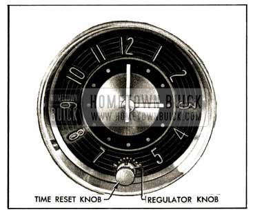
1952 Buick Clock Time Rest and Regulator Knobs
The regulator knob is located under the reset knob which extends through the glass. The regulator knob has a small notch on the edge in which a thin key or similar tool may be used to turn knob. The knob extends through the glass and has a small pointer on the inner end to align with graduations on the numeral ring of clock. See figure 10-105.
If clock loses time the regulator pointer should be moved toward “F”; if clock gains time pointer should be moved toward “S.” One division on the regulator scale is equivalent to approximately 6 minutes per day. More accurate regulation can be obtained by moving the pointer only a fraction of one division at a time and noting the results after clock has run at least 24 hours.
Winding Clock When Connecting Clock Wiring or Battery
The 1952 Buick electric clock requires special attention when reconnecting a battery that has been disconnected for any reason, a clock that has been disconnected, or when replacing a blown clock fuse. IT IS VERY IMPORTANT THAT THE INITIAL WIND BE FULLY MADE. To be certain of this, reconnect battery cables as follows:
- Make sure that all other 1952 Buick instruments are off.
- Connect one cable (preferable positive) to battery.
- Before connecting the last cable to battery, press the terminal to its post on battery.
Immediately afterward strike the terminal against battery post to see if there is a spark. If there is, allow the clock to run down until it stops ticking, and repeat as above until there is no spark. Then immediately make the permanent connection before the clock can again run down. The clock will run down in approximately 2 minutes. - Reset clock after all connections are made. NOTE: The above procedure should also be followed when reconnecting the clock after it has been disconnected, or if it has stopped because of a blown fuse. Be sure to disconnect battery cable before installing a new fuse.
Clock Service
The 1952 Buick clock manufacturers have established Authorized Service Stations in many cities throughout the United States and Canada. These service stations are prepared to carry out terms of the manufacturer’s warranty and also to perform any repairs made necessary through use of clock.
When a 1952 Buick clock requires warranty service or repairs other than regulation, it should be removed by the Buick dealer and sent to the nearest authorized service station. The manufacturer’s warranty is void if repairs have been attempted outside of an authorized service station.
10-65 1952 BUICK GASOLINE GAUGE-DASH AND TANK UNITS
The AC gasoline gauge consists of two units; the dash unit located in the 1952 Buick instrument cluster, and the tank unit located in the 1952 Buick gasoline tank. One terminal of the dash unit is connected to the ignition switch so that the unit registers only when the ignition switch is turned on. The other terminal of the dash unit is connected by a single wire to the tank unit, which is grounded on the tank to complete the circuit.
The dash unit pointer is moved by changing the magnetic pull of two coils in the unit. The magnetic pull is controlled by action of the tank unit which contains a variable rheostat, the value of which varies with movement of a float and arm. The tank unit is mounted in the tank so that the float rises and falls on the surface of the gasoline near the middle of the tank. The float is adjusted to provide approximately 1 gallon reserve when the dash unit pointer is at the dot next to the “E” position.
If the 1952 Buick gasoline gauge does not operate properly, the dash unit, tank unit wiring, and tank unit should be separately tested to determine which is at fault. The units and wiring may be tested with AC Gas gauge Tester, Type No. 1, available through AC distributors.
If this tester is not available, a similar tester may be made from a new gasoline gauge tank unit. Attach a 5-foot piece of red colored insulated wire (#16) to binding post of tank unit, and attach a similar piece of black wire to the flange of unit. Attach spring clips to the free ends of both wires.
Test of Dash Unit
- With ignition switch turned off, disconnect the tank wire (white with black parallel tracers) from dash unit terminal. Connect the red tester wire to this terminal and connect black tester wire to any convenient ground on car. Make sure that the other wire attached to dash unit has a tight connection.
- Turn ignition switch on, then move tester arm up and down against the stops. If dash unit is okay, the pointer will move freely from “Empty” to “Full” with movement of tester arm, indicating that the trouble is in wiring or tank unit. If pointer does not move, or only moves part way, the dash unit is faulty and should be replaced.
- Turn ignition switch off. If dash unit is okay, reconnect wire to terminal stud, being careful that the terminal of this wire does not come in contact with the other dash unit terminal, which would result in damage to tank unit rheostat.
Test of 1952 Buick Tank Unit Wiring
- With ignition switch turned off, disconnect tank unit wire (black, parallel tracers) at connector in luggage compartment. Connect the red tester wire to the wire running to dash unit and ground the black tester wire on car.
- Turn ignition switch on, then move tester arm up and down against stops while dash unit is being observed. If wiring is okay, dash unit pointer will move freely from “Empty” to “Full” with movement of tester arm, indicating that the trouble is in tank unit or the short wire leading to it.
- If, on the test, dash unit reads “Empty” at all times or the reading is noticeably lower than during the test of dash unit, look for a ground in the wiring between dash unit and bayonet connector. If dash unit reads above “Full” at all times or if it reads higher at “Empty” and “Full’ than readings obtained on dash unit test, look for points of high resistance such as dirty connections, broken wire strands, or open circuit.
Test of 1952 Buick Tank Unit
- If tests given above indicate that the trouble is in the tank unit, remove the gasoline tank (par. 3-13) so that the tank unit may be cleaned and tested.
- Before removing unit from gasoline tank clean away all dirt that has collected around the tank unit, and note whether the insulation was in proper position over the terminal and wire. Road dirt, particularly calcium chloride, may have caused an electrical leak that threw the tank unit out of calibration.
- After thorough cleaning and removal of tank unit, connect it to ground and to wire leading to dash unit, and test in the same manner as when using tester. If tank unit tests okay it should be reinstalled in tank, otherwise it should be replaced with a new unit. When installing tank unit make certain that insulation is folded over the terminal and snapped over wire.
10-66 1952 BUICK SPEEDOMETER
The AC pointer type speedometer head is driven by a flexible cable connected to worm gears in transmission rear bearing retainer. See paragraph 4-7 for gear ratios.
The 1952 Buick speedometer head has a magnetic speed indicator and a gear driven odometer. The trip odometer reset knob is located on lower edge of 1952 Buick instrument panel adjacent to steering column. Pushing the knob up and turning clockwise gives a quick reset; turning knob counterclockwise resets one-tenth mile at a time.
Test of 1952 Buick Speedometer Head
Wavering of speed pointer, or cable breakage, may be caused by a dry cable or binding in the 1952 Buick speedometer head. The speedometer head may be checked for binding, without removal from 1952 Buick instrument panel, by using a piece of speedometer cable 3″ or 4″ long having a tip to fit the speedometer head.
Insert the short piece of cable in speedometer head and spin it between thumb and fingers. If test cable turns freely the head is okay. If cable turns hard, or shows any tendency to bind, the head should be removed for repairs by an authorized AC Speedometer service station.
Inspection and Lubrication of 1952 Buick Speedometer Cable
If the 1952 Buick speedometer cable is noisy, or the speedometer pointer wavers, the cable should be inspected for kinks or lack of lubrication.
The AC speedometer cable is factory lubricated with a special high-low temperature grease which will last the lifetime of car under normal operating conditions. In extremely hot and dusty climates, relubrication of the cable may be necessary at intervals of approximately 20,000 miles or two years of service. When a cable is replaced, the cable must be lubricated.
- Disconnect 1952 Buick speedometer cable casing at the speedometer head, then pull cable out of upper end of casing.
- Inspect cable for worn spots or breaks. Check cable for kinks by holding one end vertically in each hand and turning cable slowly; if cable is kinked the loop will “flop.” Replace a kinked cable.
- Inspect cable casing for distortion or breaks. Look for short bends or kinks. A radius of not less than 5″ must exist at all bends in the casing.
- Spread a thin layer of special high-low temperature grease, AC Spark Plug type ST-640, over the lower two-thirds of the cable. As cable is inserted into casing from upper end the lubricant will be spread over its entire length. Do not overgrease.
- Connect casing to speedometer head, making sure that cable tip seats properly in the speedometer socket.
Replacement of 1952 Buick Speedometer Cable
Replacement cable kits listed under Group 4.342 contain a cable, cable tip, and staking tool.
The cable must be cut to required length and tip staked in place as follows:
- Cut the cable to “cutting length” shown.
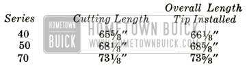
1952 Buick Speedometer Cable Lengths
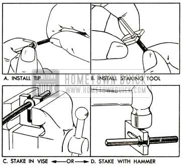
1952 Buick Installation of Speedometer Cable Tip
10-67 1952 BUICK PARKING BRAKE RELEASE WARNING SIGNAL
The 1952 Buick parking brake release warning signal, standard on Series 70 and optional on Series 40-50, is provided to show a red warning signal light whenever the car is operated while the parking brake is applied.
The signal lamp, containing a 15 CP bulb, and a switch are mounted on a bracket attached to the lower edge of 1952 Buick instrument panel just to the right of the brake lever release knob. The signal lamp is connected to the lower terminal of the ignition switch and the lead includes a fuse holder which contains a 6 ampere fuse.
The switch is located so that the brake lever depresses the plunger when the lever is in fully released position. When the parking brake is applied the lever releases the spring loaded plunger so that the switch closes the circuit to ground and the lamp bulb lights.
When brake lever is in fully released position, the signal switch plunger must be depressed 3/16″. Adjustment is made by loosening the mounting bracket screws and shifting the entire assembly as permitted by the slotted screw holes. See figure 10-107.
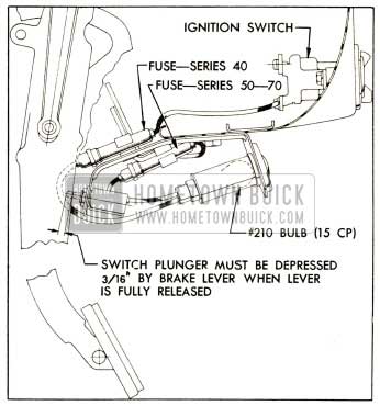
1952 Buick Parking Brake Release Warning Signal
Leave A Comment
You must be logged in to post a comment.