SECTION 5-A 1952 BUICK REAR AXLE SPECIFICATIONS AND DESCRIPTION
5-1 1952 BUICK REAR AXLE SPECIFICATIONS
Tightening Specifications
Use a reliable torque wrench to tighten the parts listed, to insure proper tightness without straining or distorting parts. The 1952 Buick Rear Axle specifications are for clean and lightly lubricated threads only; dry or dirty threads produce increased friction which prevents accurate measurement of tightness.
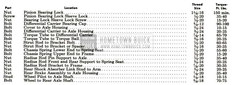
1952 Buick Rear Axle Tightening Specifications
General Specifications
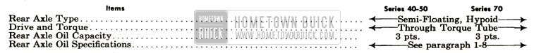
1952 Buick General Rear Axle Specifications
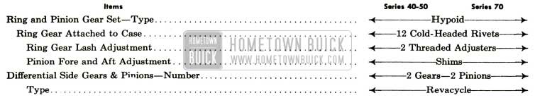
1952 Buick General Rear Axle Specification
1952 Buick Rear Axle Ratios
NOTE: The rear axle ratio is indicated by a number stamped on bottom center of axle housing.
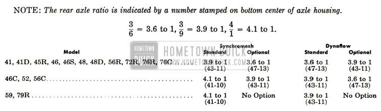
1952 Buick Rear Axle Ratios
Limits for Fitting and Adjustment of Parts
NOTE: Limits on fit of parts are for new parts only. “T” means tight and “L” means loose.
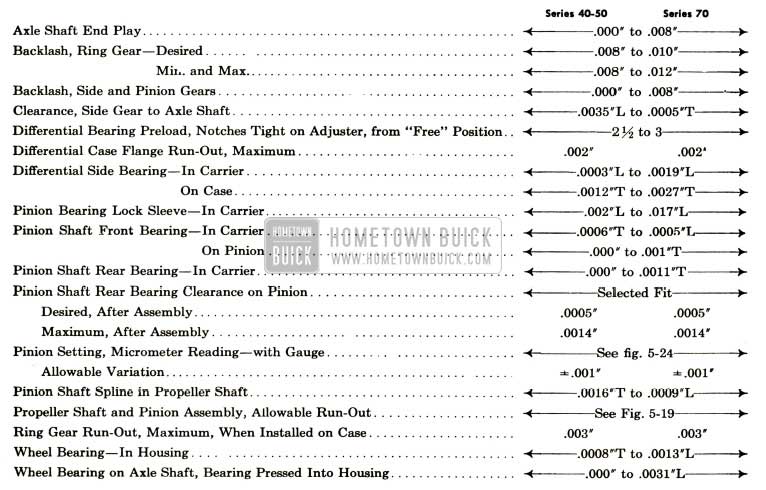
1952 Buick Rear Axle Limits for Fitting and Adjustment of Parts
5-2 DESCRIPTION OF 1952 BUICK REAR AXLE
The 1952 Buick rear axle assembly is the semi-floating type in which the load is carried on the axle shafts through bearings enclosed in the axle housing. It has a torque tube drive and a Hypoid type spiral bevel ring gear and pinion set in which the centerline of the pinion is below the centerline of the ring gear. See figure 5-l.
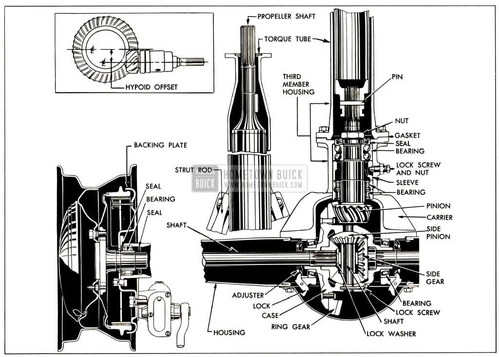
1952 Buick Rear Axle Assembly
The torque tube is joined to the differential carrier to form a unit assembly called the third member housing; the torque tube and carrier are not serviced separately. The third member housing is bolted to the banjo type rear axle housing. Two rear axle strut rods form braces between the front end of the third member housing and the outer ends of the axle housing to hold third member square with axle housing. The torque tube encloses the propeller shaft which is rigidly connected to the pinion through a splined joint and a pin. See figure 5-l.
The pinion is supported in the differential carrier by two Hyatt roller bearings (rear) and a New Departure double-row radial-thrust ball bearing (front) which is secured to the shaft by a large lock nut staked in place. A spring loaded seal bears against the lock nut to prevent escape of oil from the rear axle housing into the torque tube.
The pinion and bearing assembly is held in position by a pinion bearing lock sleeve and three cone-pointed lock screws which clamp the double-row ball bearing against a shoulder in the carrier. Shims placed between the bearing and the shoulder provide correct relation of the pinion with ring gear. See figure 5-1.
The ring gear is riveted to the differential case which is supported in the differential carrier with two differential side bearings. Threaded adjusters bearing against the outer races of the side bearings provide means of adjusting ring gear lash. The differential case also houses two differential bevel side gears in mesh with two differential bevel side pinions mounted on a shaft which is anchored in the case by a lock screw. See figure 5-1.
The splined inner ends of the axle shafts are supported by the differential side gears. “Horseshoe” washers retain the axle shafts in the side gears; washers are held in recesses in side gears when differential pinion spacer is installed. The pinion spacer is located between the inner ends of the shafts and controls end play of axle shafts. The outer ends of the axle shafts are supported in the axle housing by Hyatt roller bearings. Seals are provided on both sides of each roller bearing to exclude dirt and to prevent leakage of oil upon the brakes.
1952 Buick Rear axle is equipped with either standard or optional gear ratios. See paragraph 5-1. The rear axle ratio is indicated by numbers stamped on underside of axle housing.
Leave A Comment
You must be logged in to post a comment.