SECTION 5-A 1959 BUICK FRONT SEATS – CONVENTIONAL TYPE
5-1 1959 BUICK FRONT SEAT ASSEMBLY MANUALLY OPERATED
Description
Manually operated 1959 Buick front seat adjusters provide fore and aft movement of the seat. When the knob at the left of the seat is depressed, the seat adjusters unlock, permitting a horizontal travel of the seat. When the seat is in the desired position, the knob is released and the seat is locked.
The front seat adjusters and/or the floor pan may be reworked to reposition the 1959 Buick front seat assembly one inch forward or one inch rearward as required. See Repositioning Front Seat Assembly procedure.
1959 Buick Front Seat Assembly with Attached Seat Adjusters – Removal and Installation
- Loosen both front door opening sill plates, turn back floor covering and remove four seat adjuster-to-floor pan bolts from each adjuster.
- With the aid of a helper, remove seat assembly from body.
- To install, reverse removal procedure.
1959 Buick Front Seat Assembly Less Seat Adjusters – Removal and Installation
- Position seat midway between full forward and full rearward position. Remove seat adjuster control knob and both seat side panels.
- As a safety precaution, detach horizontal travel assist springs from the right and left seat adjuster front pedestal.
- Disengage one end of seat adjuster locking wire and remove wire from retainer bracket, located at the center front area of the seat bottom frame.
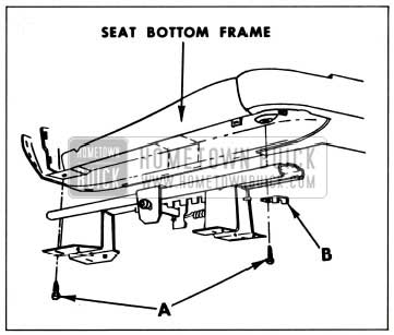
- Remove front and rear bolts securing each seat adjuster to seat bottom frame, see “A” in Figure 5-1. On four door styles, removal of front bolts permits removal of seat adjuster stop (See “B”-Figure 5-1).
1959 Buick Attachment of Manually Operated Seat Adjuster
- With the aid of a helper, remove seat assembly (less seat adjusters) from body.
- To install, reverse removal procedure.
stop on four door styles, the “U”-shaped portion of the stop must be toward the forward end of the seat assembly. The right and left sliding mechanisms should be in the same relative position when attaching adjusters to the seat bottom frame.1959 Buick Front Seat Adjuster – Manual-Removal and Installation
- Remove seat assembly with attached seat adjusters from body and place upside down on a clean protected surface.
- When removing left adjuster it is necessary to remove the seat adjuster control knob.
- Squeeze the hooked end of the seat adjuster locking wire together and slide the retaining spring back over the hump in the locking wire, remove wire from retainer on seat bottom frame and disengage locking wire from seat adjuster.
- Remove adjuster-to-seat bottom frame front and rear attaching bolts on four door styles, remove seat adjuster stop and remove seat adjuster from seat assembly.
- To install, reverse removal procedure.
CAUTION: When reinstalling seat adjuster stop, on four door styles, the “U”-shaped portion of the stop must be toward the forward end of the seat assembly. - Check operation of seat assembly. If right adjuster does not lock or unlock satisfactorily when the control handle on the left adjuster is operated, remove the screw securing the locking wire retainer to the seat bottom frame, adjust retainer to obtain proper tension in locking’ wire and reinstall retainer to seat bottom frame.
5-2 1959 BUICK FRONT SEAT ASSEMBLY ELECTRIC HORIZONTAL
Description
The electrically-operated two-way front seat assembly can be moved forward or rearward by means of a manually operated seat control switch mounted in the left seat side panel.
The 1959 Buick front seat adjusters and/or the floor pan may be reworked to reposition the entire front seat assembly one inch forward or one inch rearward as required. See Repositioning Front Seat Assembly procedure.
1959 Buick Front Seat Assembly – Electric Horizontal (With Attached Adjusters) – Removal and Installation
- Under front of 1959 Buick front seat, disconnect seat control switch wire harness from feed wire harness and detach control switch harness from clip on floor pan.
- Loosen both front door opening sill plates, turn back floor covering and remove four seat adjuster-to-floor pan attaching bolts from each adjuster. This will also disconnect ground wire.
- Remove seat assembly with attached adjusters from body.
- To install, reverse removal procedure. IMPORTANT: When installing seat assembly in body, seat adjusters should be paralleled and “in phase” with each other. In the event the adjusters are “out of phase,” (that is one adjuster reaches its full forward or rearward travel before the other adjuster) proceed as follows: Apply power source and actuate seat until left seat adjuster reaches full forward or rearward travel. Disconnect power drive cable at left side of actuator motor and actuate right adjuster until it reaches the corresponding full forward or full rearward position. Connect left adjuster power drive cable and check seat operation to full limits of fore and aft travel.
1959 Buick Front Seat Assembly – Electric Horizontal (Less Attached Adjusters) – Removal and Installation
- Position seat to gain access to front and rear bolts securing seat adjusters to seat bottom frame.
NOTE: If seat cannot be moved rearward sufficiently to permit access to the rear attaching bolts, it will be necessary to remove the 1959 Buick front seat assembly with the attached adjusters from the body. - Under front of front seat, disconnect seat control switch wire harness from feed wire harness and detach harness from clip on floor pan; disconnect both power drive cables at gearnut of each adjuster.
- At the left adjuster rear pedestal, remove inboard attaching bolt and disconnect ground wire.
- Remove seat adjuster-to-seat bottom frame bolts and remove seat assembly from body.
1959 Buick Front Seat Adjuster – Electric Horizontal – Removal and Installation
- Remove 1959 Buick front seat assembly with attached adjusters and place upside down on a clean, protected surface. (See “1959 Buick Front Seat Assembly Electric Horizontal, With Attached Adjusters-Removal and Installation” procedure).
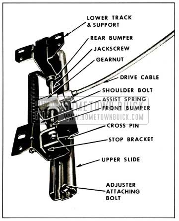
- Detach power drive cable from gearnut of adjuster to be removed; disconnect horizontal travel assist spring. See Figure 5-2.
1959 Buick Two Way Seat Adjuster
- Remove seat adjuster-to-seat bottom frame front and rear attaching bolts. Front attaching bolt is shown in Figure 5-2.
- Remove adjuster from assembly.
- To install, reverse removal procedure.
1959 Buick Front Seat Adjuster Gearnut and Jackscrew Assembly – Electric Horizontal – Removal and Installation
- Remove 1959 Buick front seat assembly with attached adjusters and place upside down on a clean, protected surface. (See “Front Seat Assembly – Electric Horizontal, With Attached Adjusters – Removal and Installation” procedure).
- Detach power drive cable from gearnut and jackscrew assembly to be removed; disconnect horizontal travel assist spring. See Figure 5-2.
- Using a suitable tool (preferably a “clutch” type screwdriver) remove two shoulder bolts securing gearnut to upper slide portion of seat adjuster assembly. See Figure 5-2.
- Remove retainer that secures stop bracket crosspin to adjuster front pedestal and remove crosspin. See Figure 5-2.
- Remove gearnut and jackscrew assembly from seat adjuster assembly.
- When installing new gearnut only, remove cotter pin, washers and rubber bumper from rear end of jackscrew and remove gearnut from jackscrew.
- When installing new jackscrew only, remove nut, washers, rubber bumper and stop bracket with inserted rubber grommet from front end of jackscrew, as well as gearnut and washers, rubber bumper and cotter pin from rear end of jackscrew.
- To install, reverse removal procedure.
1959 Buick Front Seat Adjuster Plastic Shoes – Electric Horizontal – Removal and Installation
- Remove front seat adjuster to be serviced from 1959 Buick front seat assembly. (See “Front Seat Adjuster-Electric Horizontal-Removal and Installation” procedure.)
- Using a suitable tool (preferably a “clutch” type screwdriver) remove two shoulder bolts securing gearnut to upper slide portion of seat adjuster assembly. See Figure 5-2.
- Slide lower track and support base portion of seat adjuster, with attached jackscrew and gearnut, forward until it disengages from upper slide assembly. The four plastic shoes may now be disengaged from the positioning slots on the lower track.
- To install, reverse removal procedure making sure that groove in plastic shoe slips onto the lower track with the thinner section of the shoe protruding above the surface of the track.
1959 Buick Front Seat Adjuster Actuator Motor – Electric Horizontal – Removal and Installation
- Working from underneath the front of the 1959 Buick front seat, disconnect both power drive cables and seat control switch wire harness from actuator motor.
- Remove two bolts that secure actuator motor support bracket to weld nuts at front of seat bottom frame and remove actuator motor with attached support bracket from seat assembly.
- When installing new motor, disconnect motor-to-support bracket jumper ground wire from motor and transfer support bracket with inserted rubber grommets and attached jumper ground wire from old motor to new actuator motor.
- To install, reverse removal procedure and check seat operation to extreme limit of fore and aft travel.
5-3 1959 BUICK FRONT SEAT ASSEMBLY ELECTRIC-SIX-WAY
Description
The electrically-operated six-way front seat assembly can be moved forward, rearward or tilted by means of a manually-operated seat control switch mounted in the left seat side panel. The large center control knob controls movement of the entire seat assembly horizontally or vertically. The smaller forward control knob controls the vertical movements of the front of the seat assembly causing the seat assembly to tilt. In the same manner, the rear control knob controls vertical movement of the rear of the seat assembly.
1959 Buick Front Seat Assembly – Electric Six-Way – Removal and Installation
- Under front of 1959 Buick front seat, disconnect seat control switch wire harness from feed wire harness and detach control switch harness from clip on floor pan.
- Loosen both front door opening sill plates, turn back carpeting, remove both seat adjuster track covers and remove four seat adjuster-to floor pan attaching bolts from each adjuster. The inboard rear attaching bolt at the right adjuster also fastens the lower end of the seat bottom frame-to-seat adjuster pedestal ground wire. Carpet retainers located at front of seat adjuster front floor support may now be removed.
- With the aid of a helper, remove seat assembly with attached adjusters and actuator assembly from body.
- To install, reverse removal procedure. IMPORTANT: When installing seat assembly in body, seat adjusters should be parallel and “in phase” with each other. In the event the adjusters are “out of phase” (that is, one adjuster reaches its maximum horizontal or vertical travel in a given direction before the other adjuster) proceed as follows:
- Horizontal Travel-operate seat control center switch until one adjuster reaches full forward position; at actuator motor, detach power drive cable of adjuster which has reached full forward position; operate seat forward until other adjuster also reaches full forward position; connect power drive cable and check horizontal travel of seat.
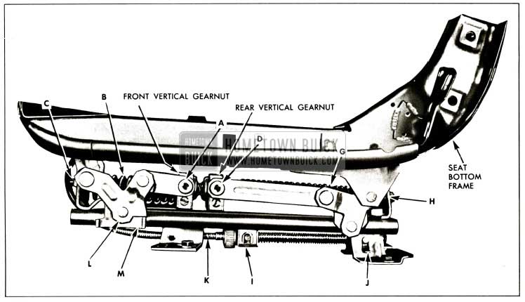
- Front Vertical Travel-operate front seat front control switch until front end of one adjuster reaches its full raised position (“U” shaped link “L” must rest on up-stop “M” as indicated in Figure 5-3); disconnect power drive cable from front vertical gearnut of adjuster which is at fully raised position; operate 1959 Buick front seat front control switch until front end of other adjuster is at fully raised position; connect power drive cable and check vertical travel of front end of the seat assembly.
1959 Buick Six-Way Combination Seat Adjuster
- Rear Vertical Travel-operate 1959 Buick front seat rear control switch until the rear end of one adjuster reaches fully lowered position; disconnect power drive cable from rear vertical gearnut of adjuster which is at fully lowered position; operate front seat rear control switch until rear end of other adjuster is at fully lowered position; connect power drive cable and check vertical travel of rear end of the seat assembly.
1959 Buick Front Seat Adjuster – Removal and Installation
- Operate seat assembly to full “up” position and % inch from full forward position.
- Remove 1959 Buick front seat assembly with attached adjusters and actuators from body and place upside down on a clean protected surface.
- Detach the three power drive cables at the adjuster to be removed.
- Remove adjuster-to-seat bottom frame front and rear bolts.
NOTE: In the event one end of the adjuster did not travel sufficiently upward to gain access to the adjuster attaching bolt, it may be necessary to disengage the linkage at that end of the adjuster from the gearnut by removing two shoulder bolts, see “A” or “D” in Figure 5-3. - Remove adjuster from seat assembly.
- To install, reverse removal procedure.
Vertical Jackscrew – Removal and Installation
- Remove 1959 Buick front seat assembly with attached adjusters and actuators from body and place upside down on a clean protected surface.
- Remove seat side panel if present.
- At the front vertical actuator motor and at the rear vertical actuator motor, detach the power drive cables connecting to the adjuster which is not being serviced.
- Connect positive terminal of a power source to seat control wire harness at feed wire connector and connect negative terminal to seat bottom frame-to-seat adjuster pedestal ground wire.
- Operate rear tilt switch so that rear of adjuster is at fully lowered position. (Rear vertical gearnut, shown in Figure 5-3 should be fully rearward.)
- Operate front tilt switch so that front of adjuster is in approximately the “half-raised” position; remove cotter pin which positions both “up” travel rubber bumpers and washers on vertical jackscrew.
- Operate front tilt switch so that front of adjuster is at fully raised position. (“U”-shaped link “L” must rest on up-stop “M” as shown in Figure 5-3.)
- Using a suitable tool (preferably a “clutch” type screwdriver) remove shoulder bolt “A,” see Figure 5-3, from each side of front vertical gearnut.
- Operate front tilt switch so that front vertical gearnut travels rearward until tension is relieved on vertical jackscrew front spring, indicated at “B” in Figure 5-3.
- From front of vertical jackscrew, remove nut and clip indicated at “C” in Figure 5-3. Locking clip also acts as the front support for the seat adjuster track cover.
- Lift front end of vertical jackscrew out of slot and remove front spring. In some cases, it may be easier to remove the spring by turning spring counterclockwise. Reinsert jackscrew into slot.
- Operate front tilt switch so that front vertical gearnut travels as far forward as possible.
- Operate rear tilt switch so that rear of adjuster is at fully raised position. (Rear vertical gearnut should be fully forward.)
- Using a suitable tool, remove shoulder bolts “D,” see Figure 5-3, from each side of rear vertical gearnut.
- Operate rear tilt switch so that rear vertical gearnut travels forward until tension is relieved on vertical jackscrew rear spring indicated at “G” in Figure 5-3.
- At rear end of vertical jackscrew, remove nut, washer and rear support for the seat adjuster track cover. See “H” in Figure 5-3.
- Disconnect the two vertical power drive cables from adjuster being serviced.
- Disengage front end of jackscrew and slide jackscrew forward until rear end of jackscrew is disengaged and remove vertical jackscrew with attached gearnuts and rear spring from assembly.
- Slide rear spring from jackscrew. Gearnuts and/or “up travel” rubber bumpers and washers can be removed from jackscrew by turning jackscrew or by temporarily attaching one of the power drive cables to each gearnut and operating seat control switch.
- To install, reverse removal procedure.
Horizontal Jackscrew – Removal and Installation
- Remove 1959 Buick front seat assembly with attached adjusters and actuators from body and place upside down on a clean protected surface.
- Pry open spring clip indicated at “I” in Figure 5-3, and disengage horizontal jackscrew front trunnion from upper horizontal track.
- Disengage rear trunnion from adjuster support by removing spring clip indicated at “J” in Figure 5-3.
- Remove horizontal jackscrew with attached trunnions and detach from horizontal power drive cable “K” in Figure 5-3.
- The rear trunnion may be removed from the jackscrew by rotating the trunnion. To remove the front trunnion from the jackscrew, remove the retaining snap ring and special fiat washer from the front (driven) end of the trunnion.
- To install; reverse removal procedure.
Actuator Motors – Front Vertical or Horizontal – Removal and Installation
- Working from underneath the front of the front seat, disconnect seat control switch wire harness and both power drive cables from actuator motor to be removed.
- Remove two bolts securing actuator motor support bracket to front seat frame bar pinchweld.
- Remove motor from seat assembly. The motor may now be removed from the support bracket by removing two attaching screws.
- To install, reverse removal procedure.
Actuator Motor – Rear Vertical – Removal and Installation
- Remove 1959 Buick front seat assembly with attached adjusters and actuators from body and place upside down on a clean protected surface.
- Disconnect seat control switch wire harness and both power drive cables from rear vertical actuator motor.
- Remove two bolts securing actuator motor support bracket to 1959 Buick front seat frame bar pinchweld.
- Remove motor from seat assembly. The motor may now be removed from the support bracket by removing two attaching screws and by disconnecting the motor-to-bracket jumper ground wire at the actuator motor.
- To install, reverse removal procedure.
5-4 1959 BUICK FRONT SEAT ASSEMBLY REPOSITIONING
To Reposition 1959 Buick Front Seat Assembly One Inch Forward:
- Remove front seat adjuster-to-floor pan attaching bolts as described in “1959 Buick Front Seat Assembly With Attached Seat Adjusters-Removal and Installation” procedure.
- Move seat assembly to one side to gain access to floor pan area below one adjuster.
- Drill a 3/8 inch diameter hole through the floor pan at the guide dimple located one inch forward of each original adjuster attaching hole.
- Repeat steps 2 and 3 at the other end of the seat assembly.
- Trim forward lower corner of rear pedestal portion of each adjuster as required to gain clearance with rise in floor pan.
- Seal original seat adjuster attaching bolt holes with body caulking compound.
- Position seat assembly over drilled holes; install original adjuster attaching bolts and secure in position with 5/1 6 inch lock washers and 5/16 x 24 hexagon nuts from underneath floor pan.
- Check seat operation and install previously removed parts.
To Reposition 1959 Buick Front Seat Assembly One Inch Rearward:
- Remove 1959 Buick front seat adjuster-to-floor pan attaching bolts as described in “1959 Buick Front Seat Assembly With Attached Seat Adjusters-Removal and Installation” procedure.
- Prop up each adjuster pedestal and drill out pilot hole to % inch diameter. (Pilot holes are located in upper surface of pedestal base plate and are one inch forward of original attaching bolt holes.)
- Reposition seat assembly one inch rearward so that new drilled holes are above weld nuts in floor pan.
- Install original seat adjuster-to-floor pan attaching bolts.
- Check seat operation and install previously removed parts.
5-5 1959 BUICK FRONT SEAT BACK UPPER TRIM PANEL ASSEMBLIES
1959 Buick Front Seat Back Upper Trim Panel Assembly – Removal – 4867 Styles
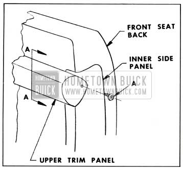
- Remove screw securing inboard end of 1959 Buick front seat back upper trim panel assembly ‘ (crash-roll) to seat back panel. See “A” in Figure 5-4.
1959 Buick Attachment of Inboard Ends of Split Back Upper Trim Panel
- Using a rubber mallet, or other suitable tool, gently tap outboard end of upper trim panel toward body centerline until attaching clips disengage from retainers on trim panel. See Figure 5-5.
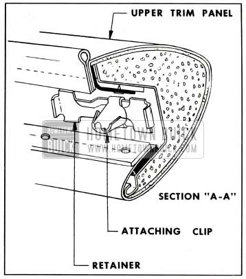
1959 Buick Trim Panel Attaching Clip Positioning
- Remove upper trim panel assembly from front seat back. Attaching clips will remain attached to supports on the seat back panel.
1959 Buick Front Seat Back Upper Trim Panel Assembly Installation – 4867 Styles
- Remove attaching clips from seat back panel and slide clips onto tapered retainer in upper trim panel assembly.
- Attach upper trim panel assembly to seat back panel by engaging attaching clips with holes in supports on the seat back panel. A rubber mallet may be used to tap the trim panel at the clip locations to insure proper clip retention.
- Install screw securing inboard end of 1959 Buick front seat back upper trim panel assembly to seat back panel.
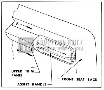
1959 Buick Front Seat Back Upper Trim Panel Assembly – Removal – 4829 and 4839 Styles
- At the back of the 1959 Buick front seat back, remove the screws securing the assist grip handle assemblies to the front seat back and remove handle assemblies. See Figure 5-6.
1959 Buick Attachment of Assist Grip Handle on Four-Door Styles
- Using a rubber mallet, or other suitable tool, gently tap end of upper trim panel assembly (crash-roll) to the left until attaching clips disengage from retainers. See Figure 5-5.
- Remove upper trim panel assembly from 1959 Buick front seat back. Attaching clips will remain attached to the supports on the seat back panel.
1959 Buick Front Seat Upper Trim Panel Assembly Installation – 4829 and 4839 Styles
- Remove attaching clips from supports on the seat back panel and slide clips onto tapered retainers in upper trim panel assembly.
- Attach upper trim panel assembly to seat back panel by engaging clips with holes in supports on the seat back panel. A rubber mallet may be used to tap the trim panel at the clip locations to insure proper clip retention.
Leave A Comment
You must be logged in to post a comment.