1959 BUICK WINDSHIELD WIPER – SINGLE SPEED
1-16 DESCRIPTION AND OPERATION
The 1959 Buick windshield wiper – single speed – consists of a rectangular shaped shunt type 12 volt motor attached to a gear box containing a gear and shaft assembly and parking switch. The motor armature has a worm shaft which drives a gear and shaft assembly. A crank arm, attached externally to the gear and shaft assembly, drives the two wiper transmissions through connecting link arms. See Figure 1-51.
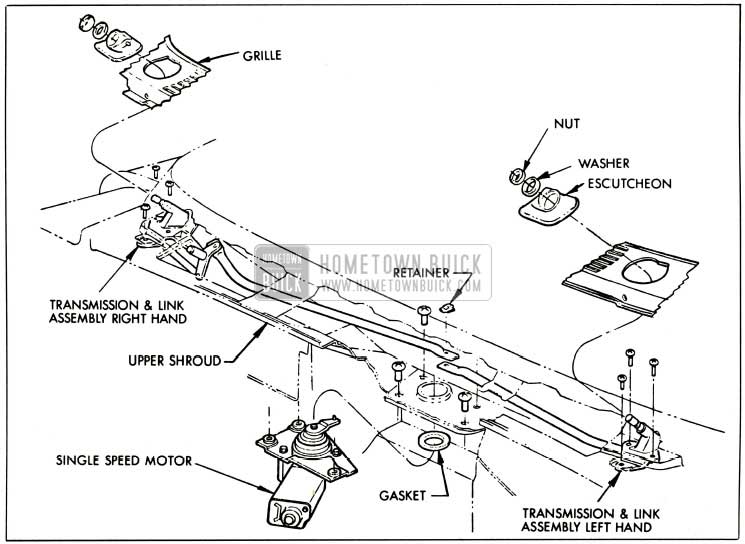
1959 Buick Single Speed Wiper Assembly (Exploded View)
An automatic reset type circuit breaker located internally on the motor brush plate protects the motor windings from overheating.
Two switches, a dash switch and parking switch control the starting and stopping of the wiper unit. The parking switch contacts, which are located internally on the wiper unit terminal board at the bottom of the wiper gear box, are actually connected across the dash switch and act as a set of holding contacts when the dash switch is turned “off.” This keeps the wiper circuit closed so the wiper can keep operating until the blades reach their predetermined park position. When the blades reach the park position, the parking switch contacts, which are controlled through the wiper gear, are opened stopping the wiper. See Figure 1-52.
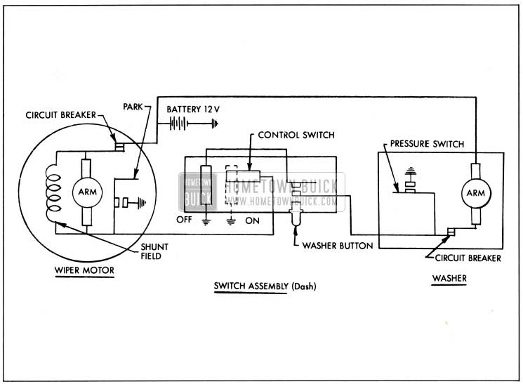
1959 Buick Wiring Diagram Single Speed System
When the wiper is turned “on” current flows from the battery through the circuit breaker, through the motor field and armature to the dash switch to ground starting the wiper.
When the wiper is first turned “off” the wiper motor circuit is opened at the dash switch. However, current from the battery then passes through the circuit breaker, motor field and armature through the parking switch contacts to ground. When the wiper blades have reached the park position the parking switch contacts open stopping the motor.
1-17 TROUBLE DIAGNOSIS
This section is divided into two parts: (A) Checking the wiper installed in the car, (B) Checking the detached wiper.
- Checking the Wiper and Washer Installed in the Car Checking an inoperative wiper in the car consists of first locating if the trouble exists in the dash switch, wiper unit or linkage. To check out the wiper system follow the steps below until trouble is located.
- Connect a jumper wire from the wiper motor frame to ground and try operating wiper. If wiper operates a defective wiper unit ground claw connection is indicated.
- With ignition switch on check for 12 volts at feed wire terminal that connects to the No.2 wiper terminal, Figure 1-52. No voltage reading indicates faulty car wiring.
- If correct voltage is obtained in step 2, connect 12 volts to No. 2 terminal, Figure 1-52 and connect a jumper wire from the No. 1 terminal to ground. If wiper operates a defective dash switch is indicated.
- If wiper fails to operate in step 3, remove body parts as necessary to gain access to wiper transmissions and linkages. Disconnect transmission link arms from wiper crank arm and recheck if wiper will operate. If wiper operates correctly trouble is located in the transmissions. If wiper still fails to operate remove wiper from car for bench check.
Checking the Detached 1959 Buick Windshield Wiper – Single Speed
There are three basic reasons for removing the wiper unit from the car for repairs: (1) Wiper Inoperative, (2) Wiper Blades Fail to Park (i.e. blades stop anyplace on glass where wiper is turned off) and (3) Wiper Fails to Shut Off.
Checking an Inoperative 1959 Buick Windshield Wiper – Single Speed
Loosen armature end play adjusting screw and check if wiper will operate. If wiper operates adjust end play. If wiper fails to operate disassemble the motor section of the wiper, (see Disassembly Instructions) and inspect or check the following items as required until trouble is located.
- Circuit breaker contacts clean and closed.
- All solder connection tight and not grounding to frame.
- Brushes slide freely in their holders and brush springs are properly positioned. (Figure 1-53.)
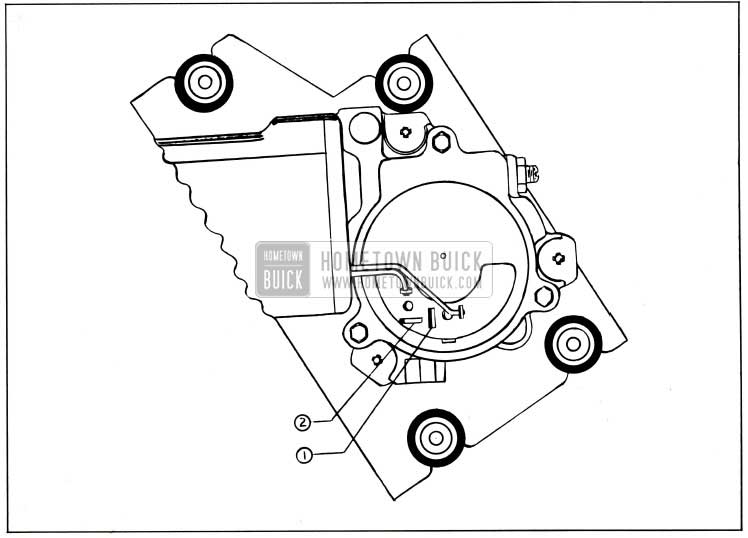
1959 Buick Checking Wiper Motor
Open – Using a test lamp check from bar to bar. If lamp fails to light between any two consecutive bars an open armature is indicated.
Grounded-Using a test lamp check between armature lamina and the commutator. If lamp lights a grounded armature is indicated.
IMPORTANT: Armature must be removed from motor and brushes must not be touching each other before making the following field checks.
Open-Using a test lamp check between terminals 1 and 2 (Figure 1-53). If lamp fails to light an open field is indicated.
Grounded-Unsolder motor lead from No. 1 terminal (Figure 1-53) and connect test lamp between disconnected lead and the motor frame. If test lamp lights a grounded field is indicated.
- Wiper Blades Fail to Park: This condition is caused by the parking switch contacts being dirty or broken. To inspect and/or clean contacts remove gear box cover, baffle and terminal board. (See Disassembly Procedure.)
- Wiper Fails to Shut Off
- Check that wiper motor lead that connects to No. 1 terminal, Figure 1-53 is not grounding on motor frame.
- Remove gear box cover, baffle and terminal board and check that contacts are not frozen or burnt together.
1-18 DISASSEMBLY AND ASSEMBLY PROCEDURES
The motor section of the wiper unit may be disassembled independently of the gear box section and vice versa.
Motor Disassembly (Refer to Figure 1-54)
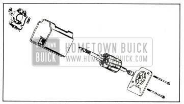
1959 Buick Single Speed Motor Disassembly
- Unsolder motor leads from terminal board.
- Remove the two tie bolts; remove end plate assembly and pull armature out of motor.
- Tap the motor frame lightly to free it from the gear box.
- Lift brush plate and circuit breaker assembly away from frame and unsolder leads as required.
To assemble the motor section reverse the disassembly procedure.
Gear Box Disassembly (Refer to Figure 1-55)
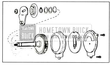
1959 Buick Gear Box Single Speed Motor Disassembly
- Remove crank arm retaining nut, crank arm, seal cap, retaining ring and end play washers.
- Remove gear box cover, terminal board and baffle and slide the gear and shaft assembly out of the gear box.
To reassemble the gear box simply reverse the disassembly procedure.
Wiper Adjustments
- Armature End Play-Loosen end play adjusting screw lock-nut (Figure 1-53) and tighten the adjusting screw until finger tight. Back off 1/4 turn and tighten lock-nut.
- Gear Shaft End Play-Remove crank arm, seal cap and retaining ring and add end play washers (Figure 1-55) as required to obtain .005″ maximum end play.
Leave A Comment
You must be logged in to post a comment.