SECTION 2-C – 1959 BUICK FRONT DOORS
2-15 DESCRIPTION
1959 Buick Front Door Assembly Typical of Sedan Styles
The following phantom view, (fig. 2-11), is typical of Sedan style front doors, with the trim assembly and inner panel water deflector removed. This illustration identifies the component parts of the 1959 Buick front door assembly, their relationship and various attaching points.
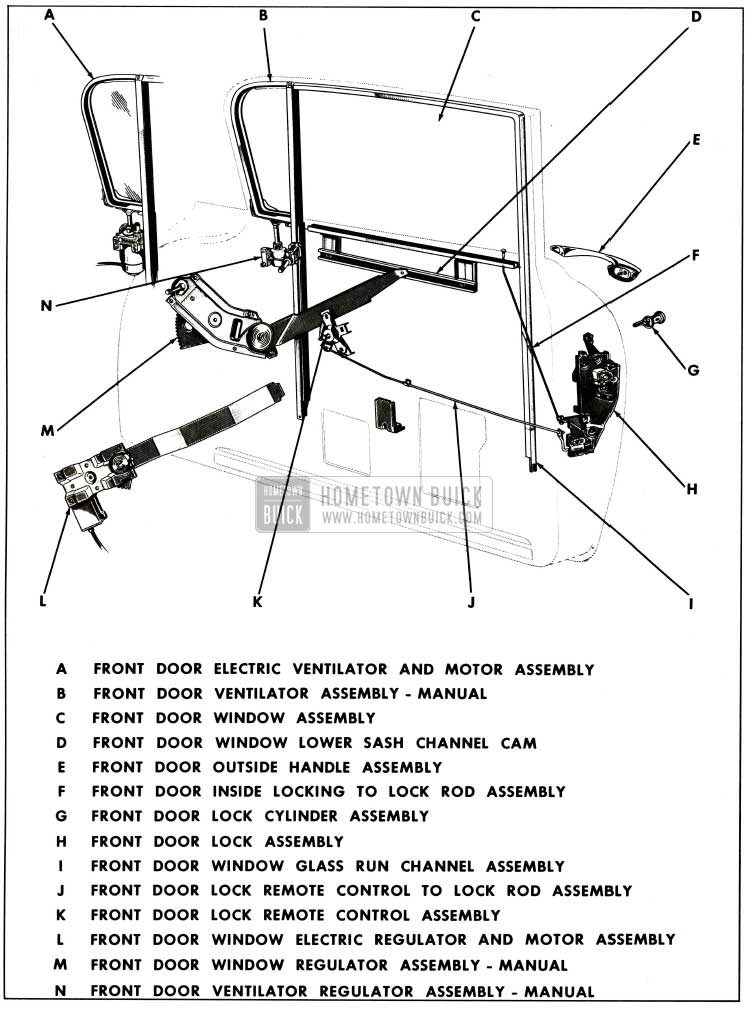
1959 Buick Front Door Assembly Typical of Sedan Style
1959 Buick Front Door Assembly Typical of Hard Top Coupe and Sedan Styles
The following phantom view (fig. 2-12), is typical of the Hard Top Coupe and Sedan style front doors, with the trim assembly and inner panel water deflector removed. This illustration identifies the component parts of the 1959 Buick front door assembly, their relationship and various attaching points.
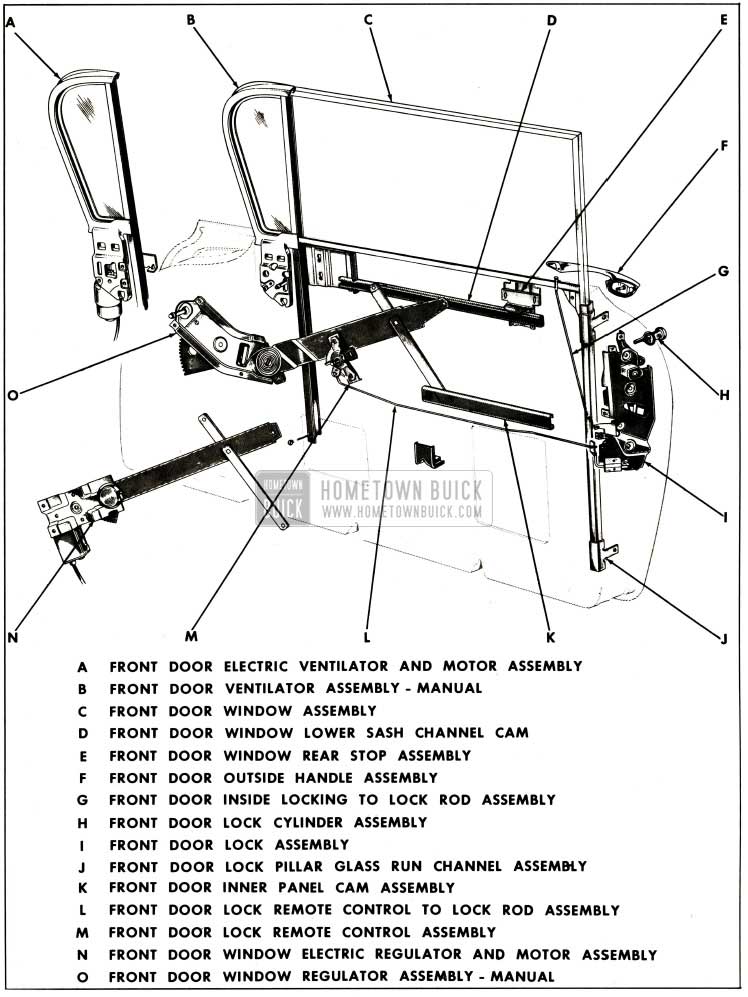
1959 Buick Front Door Assembly Typical of Hard Top Coupe and Sedan Styles
1959 Buick Front Door Assembly Adjustments Typical of Hard Top Coupe and Sedan Styles
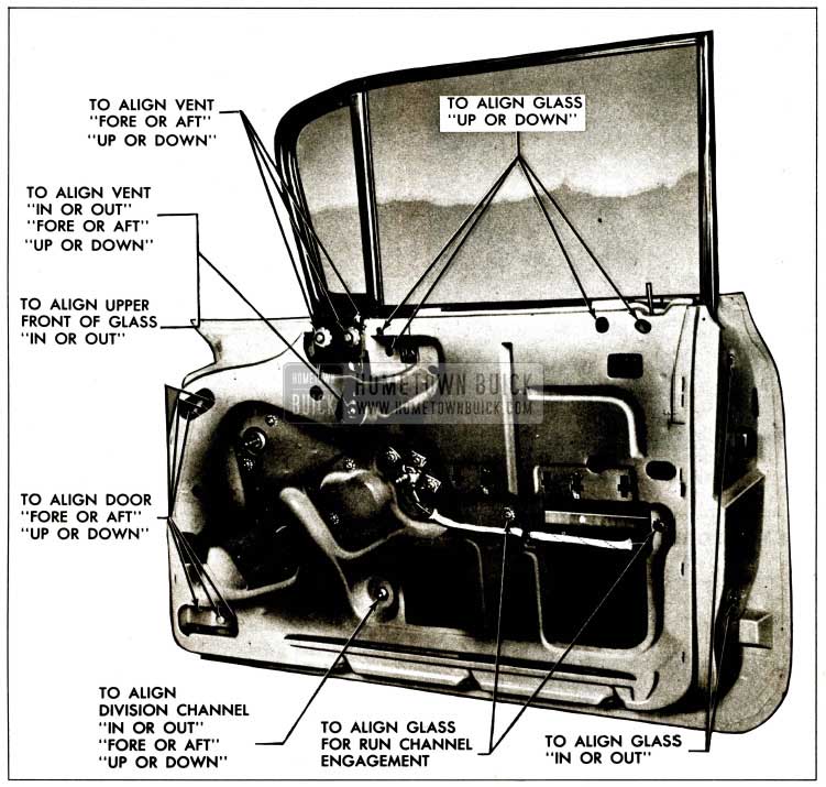
The following illustration (fig. 2-13) is typical of the Hard Top Coupe and Sedan style front door assembly. This illustration indicates the various attaching points of the component hardware parts and the adjustments which may be obtained at these locations. For a specific condition and its corresponding adjustment see “1959 Buick Front Door Window Adjustments (Manual and Electric).”
1959 Buick Front Door Assembly Adjustments-Typical
2-16 1959 BUICK FRONT DOOR ASSEMBLY AND HINGES
1959 Buick Front Door Hinges
The 1959 Buick front door hinges are the swing-out type with an integral door check and hold open, similar to past models. The hinges are attached to the front body hinge pillar and to the door assembly with bolts, cage nuts and anchor plates. Either of two (2) methods may be used to remove the door from the body.
- The door and hinges can be removed as an assembly from the body hinge pillar.
- The door can be removed from the hinge straps.
1959 Buick Front Door Hinges Removal
- Place suitable protective covering over front fender at door opening to protect finish.
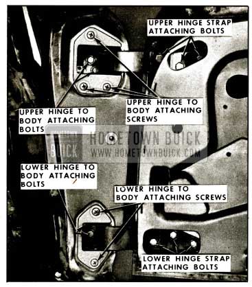
- Remove door trim assembly. Detach edge of door inner panel water deflector sufficiently to gain access to upper and lower hinge strap attaching bolts (fig. 2-14).
1959 Buick Front Door Hinges
NOTE: The above step does not have to be. performed if door and hinges are being removed, and body is not equipped with electrically-powered window regulators and/or ventilators.
- Remove two (2) screws securing electric conduit to door hinge pillar. Bend out conduit tabs and remove from wiring harness.
- Detach wiring harness from door inner panel as required and disconnect regulator motor and/or ventilator motor from harness at connectors. Remove wiring harness from between door panels through opening in door hinge pillar.
NOTE : Two bolts at upper and lower hinges are located inside of hinge boxes at front body hinge pillar.
1959 Buick Front Door Hinges Installation
- As an anti-squeak precaution, before installation of door, coat all attaching surfaces of hinges with heavy-bodied sealer, as indicated in Figure 2-15.
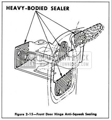
1959 Buick Front Door Hinge Anti-Squeak Sealing
- Install wiring harness in between door panels and reinstall harness to door inner panel. Connect regulator motor and/or ventilator motor assembly.
- Reinstall conduit to door hinge pillar.
1959 Buick Front Door Adjustment
Door adjustments are provided through the use of floating cage nuts and anchor plates in the door and adjacent hinge pillar. When checking the door for misalignment, remove the door lock striker from the body pillar to allow the door to hang free on its hinges. Procedure for adjusting the door is outlined below.
IMPORTANT: After performing any door adjustments on “29”,”37″,”39″ and “67” styles, the 1959 Buick front door ventilator and window should be checked for proper alignment with the side roof rail weatherstrip and adjusted, where required. In addition, the door lock extension-to-striker engagement should be checked, and if necessary, adjusted as described under “Door Lock Striker Adjustments.”
- To adjust the 1959 Buick front doors fore or aft and /or up or down, proceed as follows:
- Remove door trim assembly. Detach upper and lower front edge of door inner panel water deflector sufficiently to gain access to upper and lower hinge strap bolts (fig. 2-14).
- Mark location of hinge straps on door.
- Loosen hinge strap bolts and shift door to desired position, then retighten bolts.
NOTE: Additional up or down adjustment may be obtained at the front body hinge pillar. - Reseal upper and lower front edge of inner panel water deflector, then install previously removed door trim and inside hardware.
- To adjust 1959 Buick front doors in or out and/or up or down at front body hinge pillar, proceed as follows:
- Mark location of hinge on front body hinge pillar.
- Inside hinge box loosen hinge attaching bolts (fig. 2-14).
- Loosen hinge attaching screws at face of hinge pillar. Shift door to desired position; tighten screws at face of pillar; then tighten bolts inside hinge boxes.
2-17 1959 BUICK FRONT DOOR VENTILATOR
1959 Buick Front Door Ventilator Garnish Molding Removal and Installation
- Remove screws along front and top of ventilator garnish molding (fig. 2-16).
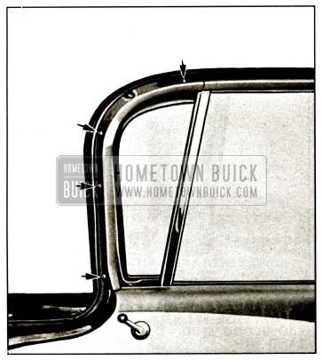
1959 Buick Front Door Ventilator Garnish Moulding
After molding is installed, apply a bead of body caulking compound at lower end of ventilator garnish molding to fill void between molding and door inner panel. Clean off all excess body caulking compound.
1959 Buick Front Door Ventilator Regulator Assembly – Removal and Installation (Manual and Electric)
- Raise door window. Remove door trim assembly and detach inner panel water deflector sufficiently to gain access to regulator attaching screws.
- On styles equipped with electric ventilator regulators, disconnect regulator motor wires at connector.
- Remove ventilator tee shaft attaching bolt and ventilator regulator attaching screws (fig. 2-17).
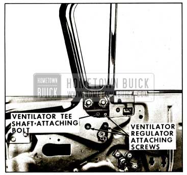
1959 Buick Front Door Ventilator Assembly
1959 Buick Front Door Ventilator Adjustments
Excessive “play” (flutter) of the ventilator at the pivot shaft, when ventilator is in open position, can be corrected by tightening ventilator tee shaft to regulator shaft attaching bolt, (fig. 2-17).
NOTE: Bolt should be tightened carefully to avoid stripping threads in regulator spiral gear shaft.
1959 Buick Front Door Ventilator Assembly – Removal and Installation (Manual and Electric) Styles 11 and 19.
- Remove door trim assembly and detach inner panel water deflector.
- Remove ventilator garnish molding and ventilator regulator as previously described.
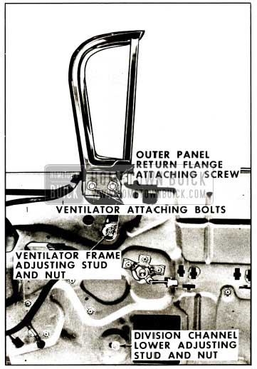
- Lower door window. Remove ventilator to door outer panel return flange attaching screw (fig. 2-18).
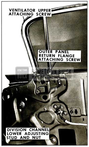
1959 Buick Front Door Ventilator Assembly – Adjustment
1959 Buick Front Door Ventilator Adjustments (11 and 19 Styles)
To adjust ventilator division channel in or out or fore and aft, remove door trim assembly and detach inner panel water deflector sufficiently to loosen division channel lower adjusting stud nut (fig. 2-18). Adjust stud in or out as required or position channel fore or aft as required, then tighten stud nut.
1959 Buick Front Door Ventilator Assembly – Removal and Installation (Manual and Electric) 29, 37,39 and 67 Styles
- Remove door trim assembly and detach inner panel water deflector.
- Remove ventilator regulator as previously described.
- Lower door window. Remove ventilator to door outer panel return flange attaching screw (fig. 2-19).
1959 Buick Front Door Ventilator Assembly Illustration
1959 Buick Front Door Ventilator Adjustments (29, 37, 39 and 67 Styles)
The 1959 Buick front door ventilator assembly can be adjusted up or down and in or out at the top for alignment in the door opening and proper weatherstrip contact in the ventilator area. The lower portion of the ventilator division channel can be adjusted in or out and fore or aft for alignment with the door window glass. The ventilator assembly can also be adjusted fore or aft for alignment with the body windshield pillar.
To adjust the ventilator assembly, proceed as follows:
- Remove door trim assembly and detach inner panel water deflector.
- Remove ventilator frame to outer panel attaching screw (fig. 2-19).
- Loosen ventilator division channel adjusting stud nut and ventilator frame adjusting stud nut (fig. 2-19).
- Loosen ventilator frame attaching bolts (fig. 2-19).
-
- To adjust upper portion of ventilator in or out, turn ventilator frame adjusting stud and ventilator division channel adjusting stud in or out, as required, then tighten stud nuts, attaching bolts and install ventilator to outer panel return flange attaching screw.
- To adjust ventilator assembly up or down, or fore or aft, position entire ventilator assembly, as required, then tighten all attaching bolts, stud nuts and ventilator to outer panel return flange attaching screw. Check door window for proper alignment and where required, adjust window as described under “FRONT DOOR WINDOW ADJUSTMENT.”
NOTE: In some cases, it may be necessary to relocate ventilator to outer panel attaching screw.
- Seal water deflector to door inner panel and install door trim and inside hardware.
2-18 1959 BUICK FRONT DOOR WINDOW ASSEMBLY
1959 Buick Front Door Window Assembly – Removal and Installation (Manual and Electric) All 11 and 19 Styles
- Lower door window. Remove door trim assembly and detach inner panel water deflector.
- Remove 1959 Buick front door ventilator as previously described under “FRONT DOOR VENTILATOR REMOVAL AND INSTALLATION.”
- On styles equipped with electric window regulator, disconnect wiring harness feed wires from regulator motor at connector.
CAUTION: DO NOT OPERATE REGULATOR MOTOR after window assembly is disengaged from regulator. Operation of motor with load removed may damage unit and make it inoperative. - Remove lower sash channel cam attaching screws (fig. 2-20).
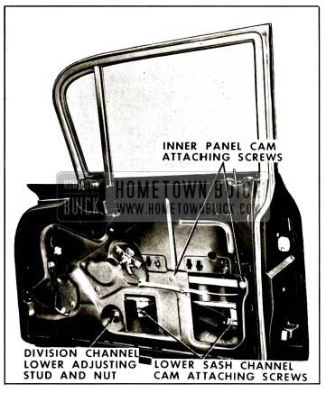
1959 Buick Front Door Window Assembly
Carefully disengage cam from lower sash channel assembly and remove through access hole. Raise window and remove from between door inner and outer panels.
1959 Buick Front Door Window Adjustments (11 and 19 Styles)
The door inner panel cam and the lower end of the ventilator division channel may be adjusted to relieve a binding door glass caused by misalignment of the window with the glass run channels.
NOTE: On all “19” styles (except 4719), the regulator is of a single lift-arm type. Because of this feature , these styles do not have an inner panel cam.
To perform the following adjustments, it is necessary to remove the door trim assembly and detach inner panel water deflector sufficiently to gain access to hardware attaching points.
- To correct a condition where the glass is “cocked” in the glass run channels, loosen the inner panel cam attaching screws, where present (fig. 2-20), adjust cam up or down as required and retighten screws.
- To adjust the lower portion of the ventilator division channel for alignment with window, lower door window and loosen ventilator division channel adjusting stud nut (fig. 2-20). Turn adjusting stud in or out or position lower end of channel fore or aft as required, then retighten stud nut.
- To adjust the lower portion of the door window glass run channel for alignment with window, lower door window. Through large access hole, loosen glass run channel lower lock pillar attaching screw at lower end of channel. Adjust channel in or out as required, then tighten attaching screw.
NOTE: Adjustments 2 and 3 may have to be coordinated in some cases to provide a properly operating 1959 Buick front door window assembly.
1959 Buick Front Door Window Glass Run Channel Assembly – Removal and Installation (All 11 and 19 Styles)
- Remove door window assembly as previously described.
- At lower lock pillar end of glass run channel, loosen attaching screw.
- Disengage glass run channel along lower door lock pillar section by carefully prying channel assembly from window frame.
- Squeeze glass run channel together along top and sides, pull or carefully pry channel from window frame and remove channel from door.
- To install, reverse removal procedure.
1959 Buick Front Door Window Assembly – Removal and Installation (Manual and Electric) All 27, 37, 39 and 67 Styles
- Raise door window. Remove door trim assembly and detach inner panel water deflector.
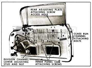
- Through access holes in inner panel (fig. 2-21) loosen 1959 Buick front door window front stop assembly attaching screws.
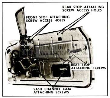
1959 Buick Front Door Window Assembly Removal
CAUTION: DO NOT OPERATE REGULATOR MOTOR after window assembly is disengaged from regulator. Operation of motor with load removed may damage unit.
1959 Buick Front Door Window Assembly Adjustments (Manual and Electric)
The door window glass may be adjusted to provide proper contact with the side roof rail weatherstrip. Adjustments have also been provided to relieve a binding door glass due to misalignment of the glass run channels. To perform the following adjustments, remove door trim assembly and detach inner panel water deflector, where necessary, to gain access to hardware attaching points; then proceed as follows:
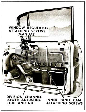
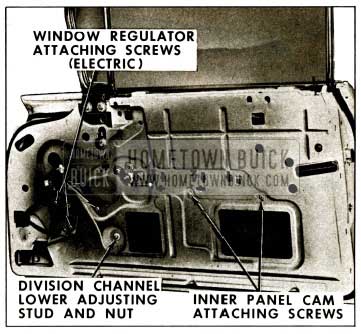
- To correct a condition where glass is “cocked” in glass run channels, loosen inner panel cam attaching screws (figs. 2-22 and 2-23). Adjust cam up or down as required and retighten screws.
1959 Buick Front Door Window Adjustments-Hardtop Sedans
1959 Buick Front Door Window Adjustments-Hardtop Coupes
NOTE: Adjustments 2, 3 and 4 may have to be coordinated in some cases to provide a properly operating 1959 Buick front door window assembly.
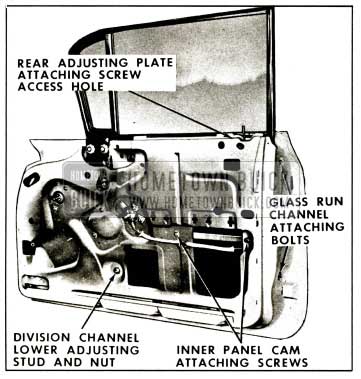
1959 Buick Front Door Lock Pillar Glass Run Channel Assembly – Removal and Installation (All 19, 37, 39 and 67 Styles)
- Remove door trim assembly and detach inner panel water deflector.
- Remove glass run channel attaching bolts on face of lock pillar (fig. 2-24) and remove channel assembly from door through large access hole.
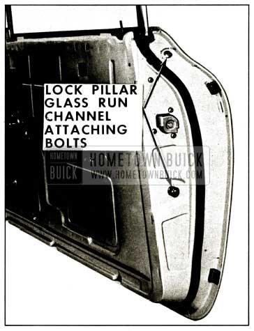
1959 Buick Lock Pillar Glass Run Channel
1959 Buick Front Door Window Regulator Assembly (Manual and Electric)
- Lower door window. Remove door trim assembly and detach inner panel water deflector.
- On styles equipped with electric window regulators, disconnect wiring harness feed wires from regulator motor at connector.
CAUTION: DO NOT OPERATE REGULATOR MOTOR after window assembly is disengaged from regulator. Operation of motor with load removed may damage unit. - Remove ventilator division channel lower adjusting stud and nut (figs. 2-25 and 2-26).
1959 Buick Front Door Window Regulator Removal
1959 Buick Front Door Window Regulator Removal Illustration
NOTE: Instructions for removing motor from regulator assembly are outlined under “REMOVAL AND INSTALLATION OF FRONT DOOR WINDOW REGULATOR ELECTRIC MOTOR ASSEMBLY.”
1959 Buick Front Door Window Regulator Electric Motor Assembly – Removal and Installation
The electric motor assembly, which powers the window regulator on electrically operated windows, is a twelve volt reversible direction motor with a built-in circuit breaker and a self-locking gear drive. The motor is secured to the regulator assembly with screws.
- Remove 1959 Buick front door electric window regulator assembly as previously described.
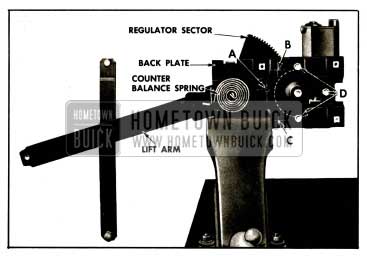
- Clamp electric window regulator securely in vise (fig. 2-27).
1959 Buick Front Door Window Electric Regulator
NOTE: The position of regulator assembly in vise will vary with type of regulator, and position of lift arm.
CAUTION: BE SURE TO PERFORM STEPS 8 AND 4 BEFORE ATTEMPTING TO REMOVE MOTOR FROM REGULATOR. The regulator lift arm, which is under tension from the counter-balance spring, can cause serious injury if motor assembly is removed without locking the sector in position with a nut and bolt.
NOTE: Do not drill into motor housing, part of which is indicated by dotted lines. In addition, locate hole not less than 3/4″ away from edge of back plate or sector.
NOTE: Clean off steel chips from regulator sector and motor pinion gear.
NOTE : Be sure to remove temporary nut and bolt from regulator before installing it into door.
2-19 1959 BUICK FRONT DOOR LOCKS
1959 Buick Front Door Lock Spring Clip
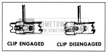
A spring clip is used on the door lock levers to secure the connecting rods to the lock levers. A slot in the spring clip provides easier disengagement of the clip thereby facilitating easier detachment of the lock connecting rods from the lock assembly.
To disengage spring clips, use a screw driver or other suitable tool to slide clip out of engagement. Figure 2-28 shows a door lock spring clip engaged and disengaged.
1959 Buick Door Lock Spring Clip
1959 Buick Front Door Lock Assembly – Removal and Installation
All locks are the rotary bolt type lock with the inter lock feature similar to those used on past models. With the inter lock feature it is very important that the lock extension engages properly in the door lock striker notch and that, where necessary, striker emergency spacers of the proper thickness are used to obtain proper engagement.
Removal and Installation
- Raise door window. Remove door trim assembly and detach inner panel water deflector. On “19,” “29” and “39” styles, remove door lock cylinder assembly.
- Through access hole disengage spring clip and detach remote control rod from lock assembly (fig. 2-29).
1959 Buick Front Door Lock Assembly Removal
NOTE: On “11,” “97” and “67” styles, remove inside locking control rod from lock assembly as a bench operation.
NOTE: In some cases on “97” and “67” styles, it may be necessary to loosen the lock pillar glass run channel upper and lower attaching bolts sufficiently to obtain additional rearward movement of the lock assembly to allow removal of lock bolt housing from lock pillar facing.
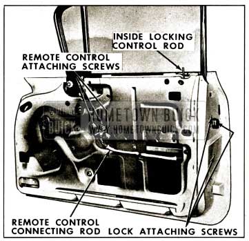
1959 Buick Front Door Lock Remote Control and Connecting Rod Removal and Installation
- Raise door window. Remove door trim assembly and detach inner panel water deflector.
- Remove remote control attaching screws (fig. 2-30). Remove remote control and carefully disengage remote control from remote control connecting rod.
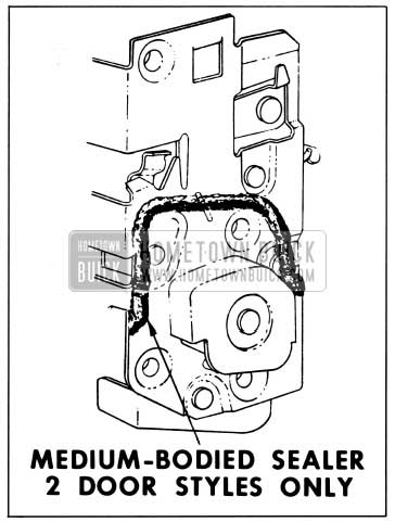
1959 Buick Front Door Lock Sealing
1959 Buick Front Door Outside Handle Assembly – Removal and Installation
- Raise door window. Remove door trim assembly and detach inner panel water deflector sufficiently to gain access to door outside handle attaching screw access holes (fig. 2-31).
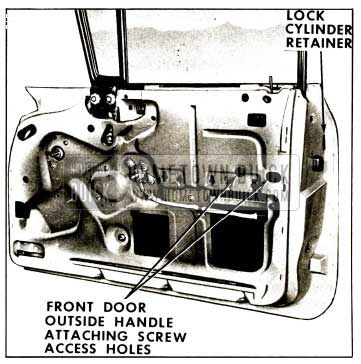
1959 Buick Front Door Outside Handle and Lock Cylinder Removal
1959 Buick Front Door Outside Handle Push Button – Disassembly and Assembly
- Remove door handle from door assembly.
- Depress retainer slightly and turn retainer one-quarter turn. Remove retainer, spring and push button and shaft from handle (fig. 2-32).
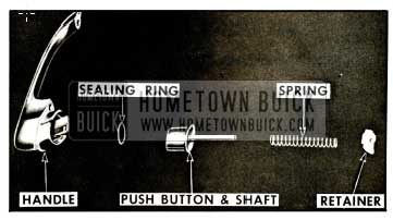
1959 Buick Front Door Outside Handle Assembly
1959 Buick Front Door Lock Cylinder Assembly – Removal and Installation (All 19, 29 and 39 Styles)
- Remove 1959 Buick front door outer panel molding as described under “Front Door Outer Panel Molding-Removal and Installation.”
- With a suitable tool, pry out lock cylinder retaining clip (fig. 2-31) sufficiently to allow removal of cylinder, then remove cylinder and gasket.
- To install, insert cylinder with curved edge of pawl toward door hinge pillar and reverse removal procedure. Using key, check operation of lock cylinder assembly. Install previously removed door outer panel molding.
1959 Buick Front Door Lock Cylinder Disassembly and Assembly
- Remove cylinder assembly from door.
- With suitable tool, remove retaining clip and remove pawl (fig. 2-33).
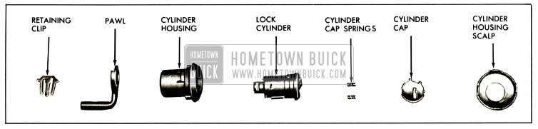
1959 Buick Front Door Lock Cylinder Assembly – Sedan Styles
NOTE: While removing scalp, hold cylinder cap, which is under tension from cap springs, depressed with finger. After scalp is removed , observe position of springs and cap so that they can be reinstalled in same relative positions.
1959 Buick Front Door Lock Cylinder Assembly – Removal and Installation (All 11, 37 and 67 Styles)
- Raise door window. Remove door trim assembly and detach inner panel water deflector.
- Remove 1959 Buick front door outer panel molding as described under “Front Door Outer Panel Molding-Removal and Installation.”
- Through large access hole detach lock cylinder connecting rod from lock lever. To detach connecting rod, disengage clip, insert a screw driver between connecting rod and lock lever, then snap rod from spring clip on lock lever.
- With a suitable tool pry out retaining clip (fig. 2-31) sufficiently to allow removal of lock cylinder with attached connecting rod from door.
- Door lock cylinder connecting rod may be removed from lock cylinder assembly as a bench operation.
- To install, reverse removal procedure. Check operation of lock cylinder assembly and lock assembly before installing water deflector, door trim assembly and hardware parts.
1959 Buick Front Door Lock Cylinder Disassembly and Assembly
- Remove cylinder assembly from door.
- Remove retaining clip and pawl (fig. 2-34).
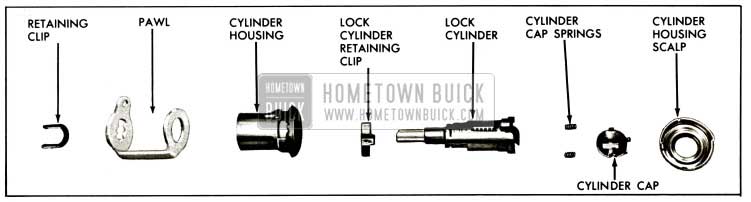
1959 Buick Front Door Lock Cylinder Assembly-37 and 67 Styles
NOTE: While removing scalp, hold cylinder cap, which is under tension from cap springs. After scalp is removed, observe position of spring and cap so they can be reinstalled in the same relative positions.
Leave A Comment
You must be logged in to post a comment.