SECTION 7-G 1959 BUICK HYDRO-LECTRIC SYSTEM
7-12 DESCRIPTION AND OPERATION
Description
The hydraulic unit which is used in the Convertible bodies, consists of a 12-volt reversible type motor, a rotor-type pump, two hydraulic lift cylinders, and an upper and lower hydraulic hose assembly. It is important to note that the folding top cannot be operated manually. Figure 7-36 shows the unit installed in the body directly behind the rear seat back.
1959 Buick Hydro-Lectric Pump and Motor Installation
Figure 7-37 shows an exploded view of the motor and pump assembly. The part indicated by letters may be identified in the description.
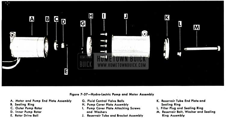
1959 Buick Hydro-Lectric Pump and Motor Assembly with Legend
Operation of the Folding Top
When the control switch knob is actuated to the “up” position the battery feed wire is connected to the red motor lead and the motor and pump assembly operate to force the hydraulic fluid through the hoses to the lower ends of the double-acting cylinders. The fluid forces the piston rods in the cylinders upward, thus raising the top. The fluid in the top of the cylinders returns to the pump for recirculation to the bottom of the cylinders. When the control switch knob is actuated to the “down” position, the feed wire is connected to the dark green motor lead and the motor and pump assembly operate in a reversed direction to force the hydraulic fluid through the hoses to the top of the cylinders. The fluid forces the piston rods in the cylinders downward1 thus lowering the top. The fluid in the bottom of the cylinders returns to the pump for recirculation to the top of the cylinders.
Operation of Pump Assembly
The motor type pump assembly is designed to deliver a maximum pressure in the range of 240 psi to 280 psi. The operation of the pump assembly when raising the top is as follows:
- Raising the Top. When the red motor lead is energized, the motor drive shaft turns the rotors clockwise as indicated by the large arrow in Figure 7-38.
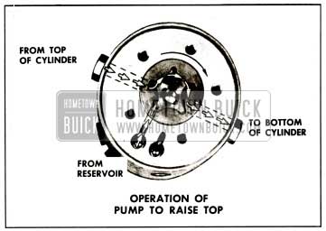
1959 Buick Operation of Pump To Raise Top
The action of the pump rotors forces the fluid under pressure to the bottom of each cylinder forcing the piston upward. This action causes the fluid above the piston in each cylinder to be forced into the pump, which re-circulates the fluid to the bottom of the cylinders. The additional fluid required to fill the cylinder due to piston rod displacement is drawn from the reservoir as indicated in Figure 7-38.
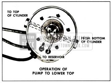
1959 Buick Operation of Pump To Lower Top
The action of the pump rotors forces the fluid under pressure to the top of each cylinder. This action causes the fluid below the piston in each cylinder to be forced into the pump which re-circulates the fluid to the top of each cylinder. The surplus hydraulic fluid due to piston rod displacement flows into the reservoir as shown in Figure 7-39.
Fluid Control Valve
The fluid control valve consists of a rocker arm installed in the pump cover plate, and two steel balls. Figure 7-39 shows the top surface of the pump cover plate. The dotted lines indicate the cavities on the bottom side of the cover plate. The cavities are designed to permit fluid flow between pump rotors and the reservoir.
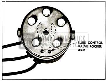
1959 Buick Pump Cover Plate
Figures 7-41 and 7-42 illustrate the operation of the fluid control valve.
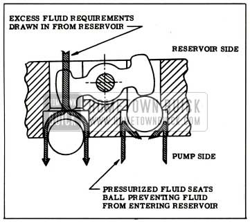
1959 Buick Fluid-Control Valve
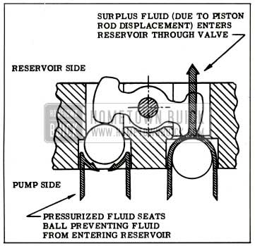
1959 Buick Fluid Control Valve Illustration
7-13 CHECKING PROCEDURES
Mechanical Checking Procedure
If there is a failure in the 1959 Buick Hydro-Lectric system and the cause is not evident the mechanical operation of the top should first be checked. If the folding top assembly appears to have a binding action disconnect the top lift cylinder piston rods from the top linkage and then manually raise and lower the top. The top should travel through its up and down cycle without any evidence of a binding action. If a binding action is noted when the top is being
locked at the header, check the alignment of the door windows, ventilators and rear quarter windows with relation to the side roof rail weatherstrips. Make all necessary adjustments for correct top alignment. If a failure continues to exist after a check for mechanical failure has been completed the 1959 Buick Hydro-Lectric system should then be checked for electrical or hydraulic failures.
Electrical Checking Procedure
If a failure in the 1959 Buick Hydro-Lectric system continues to exist after the mechanical operation has been checked the electrical system should then be checked. A failure in the electrical system may be caused by a low battery, breaks in the wiring, faulty connections, mechanical failure of an electrical component, or wires or components shorting to one another or to the body metal. Before beginning checking procedure, check battery according to recommended procedure.
- Checking for Current at the Folding Top Control Switch.
- Disengage terminal block from rear of switch.
- Connect light tester to central feed terminal of switch terminal block.
- Ground light tester ground lead to the body metal.
- If light tester does not light there is an open or short circuit between power source and switch.
- Checking the Folding Top Control Switch.
If there is current at the feed wire terminal of the terminal block the operation of the switch can be checked as follows:- Place a No. 12 jumper wire on switch terminal block between center terminal (feed) and one of two motor wire terminals. If motor operates with jumper wire but did not operate with switch, the switch is defective.
- Connect jumper wire between center terminal (feed) and other motor wire terminal on switch terminal block. If motor operates with jumper wire, but did not operate with switch, the switch is defective.
- Checking Switch to Motor Lead Wires.
If switch is found to be operating properly, the switch to motor lead wires can be checked as follows (See Figure 7-43):
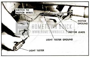
1959 Buick Checking Motor Wiring
- Disconnect green switch-to-motor wire from motor lead in rear compartment.
- Connect a light tester to green switch-tomotor wire terminal.
- Ground light tester ground lead to body metal.
- Actuate switch to “down” position. If tester does not light, there is an open or short circuit in wire.
- Disconnect red switch-to-motor wire from motor lead.
- Connect light tester to red switch-to-motor wire terminal.
- Actuate switch control knob to “up” position. If tester does not light, there is an open or short circuit in wire.
If a light tester indicates current at the motor lead terminals of the switch-to-motor wires but the motor unit does not operate from the switch, a final check of the motor unit can be made as follows:
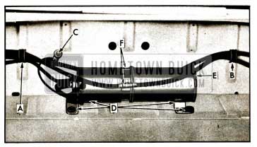
- Check connection of motor ground wire to body metal. See “C” in Figure 7-36.
- Connect No. 12 jumper from battery positive pole to motor lead terminal that connects to green switch-to-motor wire. The motor should operate to lower top.
- Connect jumper wire to motor lead terminal that connects to red switch-to-motor wire. The motor should operate to raise top.
- If motor fails to operate on either or both of these checks, it should be repaired or replaced.
- If motor operates with jumper wire but will not operate from switch-to-motor wires, the trouble may be caused by reduced current resulting from damaged wiring or poor connections.
Hydraulic Checking Procedure
Failures in the hydraulic system can be caused by lack of hydraulic fluid, leaks in hydraulic system, obstructions or kinks in hydraulic hoses or faulty operation of a cylinder or the pump. A pressure gauge can be used to check the pressure of the pump. See “Checking the Pressure of the Pump.”
- Checking Hydraulic Fluid Level in Reservoir.
- Operate top to raised position.
- At the rear compartment, remove pump and motor shield.
- Place absorbent rags below reservoir at filler plug.
- With a straight-bladed screw driver, remove filler plug. Fluid level should be at the lower edge of filler plug hole.
- If fluid is low, add Delco No. 11 Hydraulic Fluid (G.M. Hydraulic Brake Fluid Super No. 11) to bring to specified level.
- Reinstall filler plug and pump and motor shield.
- Checking Operation of Lift Cylinders.
- Remove rear seat cushion and folding top compartment side panel assembly.
- Operate folding top control switch and observe the lift cylinders during “up” and “down” cycles for these conditions:
- If movement of cylinder is not coordinated, or sluggish when the motor is actuated, check hydraulic hoses from motor and pump to cylinder for kinks.
- If one cylinder rod moves slower than the other, cylinder having slower moving rod is defective and should be replaced.
- If both cylinder rods move slowly or do not move at all, check the pressure of the pump. See “Checking the Pressure of the Pump.”
NOTE: To insure proper operation of the lift cylinders, the top lift cylinder rods should be cleaned and lubricated at least twice a year. To perform these operations, raise top to “up” position and wipe exposed portion of each top lift cylinder piston rod with a cloth dampened with brake fluid to remove any oxidation and/or accumulated grime. With another clean cloth apply a light film of brake fluid to the piston rods to act as a lubricant.
CAUTION: Exercise care so that brake fluid does not come in contact with any painted or trimmed parts of the body.
- Checking Pressure at the Pump.
- Remove motor and pump assembly from rear compartment.
- Install plug in one port, and pressure gauge in port to be checked, as indicated in Figure 7-44.
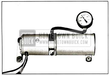
1959 Buick Checking Pump Pressure
NOTE: A difference in pressure readings may exist between the pressure port for top of cylinders and pressure port for bottom of cylinders. This condition is acceptable if both readings are within the limit of 240 psi. and 280 psi.
7-14 DISASSEMBLY AND ASSEMBLY PROCEDURES
Motor and Pump Assembly – Removal
- Operate the folding top to the full “up” position.
- Disconnect the positive battery cable.
- Place protective covering over the rear seat back and cushion.
- Working inside the body, detach the front edge of the folding top compartment bag from rear seat back panel.
- Working on the inside of the body over the rear seat back, remove the pump and motor shield attaching screws and remove shield.
- Remove the clips “A” and “B,” Figure 7-36, securing the wire harness and the hydraulic hose to the rear seat back panel.
- Disconnect the motor leads from the wire harness and ground attaching screw “C,” Figure 7-36.
- To facilitate removal apply a rubber lubricant to pump attaching grommets “D,” Figure 7-36, then carefully disengage grommets from floor pan.
- Place absorbent rags below hose connections and end of reservoir.
- With a straight-bladed screw driver, vent the reservoir by removing the filler plug indicated at “E,” Figure 7-36, then reinstall plug.
NOTE: Venting the reservoir is necessary in this “sealed-in” unit to equalize the air pressure in the reservoir to that of the atmosphere. This operation prevents the possibility of the hydraulic fluid being forced under pressure from disconnected lines and causing damage to trim or body finish. - Disconnect hydraulic lines at “F,” Figure 7-36, and cap open fittings to prevent leakage of fluid. Use a cloth to absorb any leaking fluid, then remove the unit from the rear compartment.
Motor and Pump Assembly Installation
- If a replacement unit is being installed, fill reservoir unit with specified Delco No. 11 Hydraulic Fluid (G.M. Hydraulic Brake Fluid Super No. 11). See “Checking Fluid in Reservoir” for proper fluid level.
- Connect hydraulic hoses, engage attaching grommets in panel and connect wiring.
- Remove reservoir filler plug and place absorbent rags under filler opening.
- Connect battery and operate top through its up and down cycle with filler plug removed from reservoir.
- Check connections for leaks and check fluid level in reservoir. See “Checking Fluid in Reservoir” for proper level.
- Install previously removed parts.
Reservoir Tube Disassembly from Motor and Pump Assembly
- Remove motor and pump assembly from body.
- SCRIBE A LINE across the pump end plate, reservoir tube and reservoir tube end plate as shown in Figure 7-45 to insure correct assembly of parts.
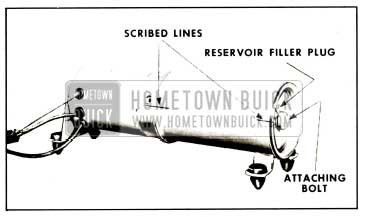
1959 Buick Reservoir Tube Disassembly From Motor and Pump
Reservoir Tube Assembly to Motor and Pump Assembly
- Position sealing ring on pump and assemble reservoir tube to pump according to scribe marks.
NOTE: Bracket assembly on tube should be located at outer end when tube is assembled to pump. - Position sealing ring on tube end plate and place end plate on reservoir tube, lining up the scribe marks. Install and tighten attaching bolt.
- Place unit in horizontal position and fill with fluid until level of fluid is even with bottom of filler plug hole.
- Make sure that sealing ring is on the filler plug, before installing filler plug.
Removal of Folding Top Lift Cylinder
- Remove rear seat cushion and seat back.
- Remove folding top compartment side trim panel.
- With the top in the raised position, remove attaching nut, bolt, bushing and washer from upper end of cylinder. See “C” in Figure 7-46.
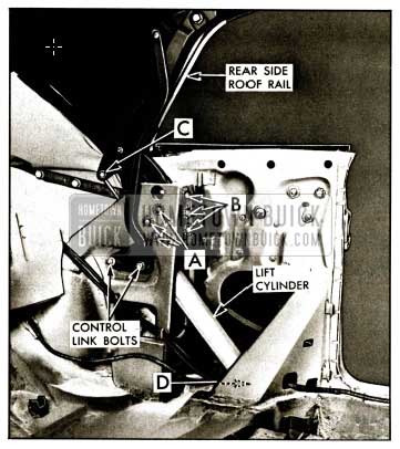
1959 Buick Lift Cylinder Removal
CAUTION: Before disconnecting the hydraulic connections, place suitable wiping rags under the connections to absorb any drippage of hydraulic fluid. Also, disconnect the battery positive cable to prevent the accidental operation of the motor and pump while the hydraulic hoses are disconnected.
Leave A Comment
You must be logged in to post a comment.