SECTION 5-B 1958 BUICK VARIABLE PITCH DYNAFLOW TRANSMISSION TROUBLE DIAGNOSIS ADJUSTMENTS ON CAR
5-9 1958 BUICK VARIABLE PITCH DYNAFLOW TEST AND INSPECTION
Road Test
When improper operation of a 1958 Buick Variable Pitch Dynaflow transmission is reported, time and expense will usually be saved by first making a thorough road test to observe operation in all ranges under appropriate driving conditions. The road test will also serve to thoroughly warm up the transmission, which is required for any tests made in the shop.
The person making the road test should be familiar with the operation and performance of Dynaflow Drive in all ranges so that he will be able to detect any sub-standard condition. The required “feel” of a Dynaflow car can best be acquired by driving through a test routine on a number of cars whose performance is known to be satisfactory. Knowledge of which parts are in operation and which hydraulic controls govern operation in each range is essential to intelligent diagnosis, therefore, a study of paragraphs 5-4 through 5-12 is recommended.
After the transmission has been warmed up to normal operating temperature, thoroughly test operation in all ranges, making tests on steep grades as well as on level road, if possible. While in Direct Drive test shifting of the 1958 Buick variable pitch stator by pressing accelerator pedal to floor mat a number of times. A slight surge or change of engine speed accompanied by acceleration pick-up should be noted, indicating that the stator has shifted to the high angle position.
Test operation when shifting between Low and Direct Drive under load, also test operation in Direct Drive after extended operation in Reverse. Check for abnormal slip or over-run of the engine on low speed acceleration. With car stopped on level road and brakes released, check for creep when engine is accelerated with transmission in Neutral. Check for abnormal creep with engine idling and transmission in each of the driving ranges.
Place transmission in Direct Drive and firmly apply the brakes. Snap the throttle open to give engine speed of approximately 1400 RPM and immediately release the accelerator pedal. If the engine returns to idle too slowly, or else returns to idle so fast that it either stalls or rolls unevenly, improper throttle linkage and dash pot adjustment is indicated. Rough operation on idle after slow deceleration indicates the need for some engine tune up adjustments.
During all tests, be alert for any unusual or abnormal noises. Carefully note the range, speed and other conditions under which the noise is evident.
Shop Inspection and Test
After the road test described above, a number of shop inspections and tests should be made while the transmission is thoroughly warmed up to operating temperature.
- Check Oil Level. In every case of a transmission complaint first check the oil level as described in paragraph 1-1 (step 7). If oil level is low bring it to proper level and check the effect on operation before doing further work. If oil level is low and the car history indicates oil loss of one pint or more per 1000 miles, or transmission exterior is oily, a thorough inspection for oil leakage should be made as described in paragraph 5-11.
- Check Manual Control Linkage. In cases of improper operation in one or more ranges it is always advisable to check the adjustment of transmission manual control linkage as described in paragraph 5-12.
- Test Oil Pressures in Hydraulic Control System. When diagnosing almost all cases of improper operation it is necessary to have accurate knowledge of oil pressures in the hydraulic control system. The following oil pressure tests should be made before performing any mechanical work.
- Check Engine and Transmission Mountings. Check the engine and transmission mounting bolts and condition of the rubber mountings and thrust pad. Also check for any marks on the converter housing, transmission case or oil pan that would indicate that these parts had been damaged by some obstruction, which might affect alignment of the transmission.
Testing Hydraulic Control Oil Pressures
Before making the pressure tests oil level must be correct (par.1-1, step 7) and the transmission must be thoroughly warmed up to operating temperature. Place rear end of car solidly on car stands or use a free wheel type hoist so that plugged ports can be reached and transmission can be operated with rear wheels free to turn.
Remove pipe plug at the following points in turn and connect Pressure Gauge J 2575. (1) Front oil pump, on left side of transmission case. (2) Rear oil pump, in lower flange at front end of rear bearing retainer. (3) High or low accumulator, on front upper corner of accumulator body. (4) Stator, on left end of reaction shaft flange. See figure 5-26.
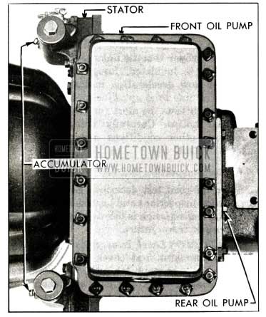
1958 Buick Gauge Connections for Oil Pressure Tests
Run engine at 500 RPM and test pump and accumulator pressures in Low, Drive and Reverse. Test front oil pump in all ranges and rear oil pump in all but Reverse. Test high accumulator only in Drive and test low accumulator only in Low. Repeat tests at 1000 RPM and 1800 RPM in Low and Drive only. The following pressures should be obtained on these tests.
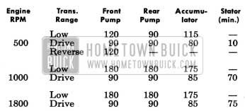
1958 Buick Test Pump and Accumulator Pressures
Low or erratic oil pump pressure indicates an air leak into the pump suction line, faulty pressure regulator valve operation, or excessive clearance in pump. Low rear pump pressure also may be caused by a leak in the valve and servo body passages which connect the rear pump with the pressure regulator valve. If pressure of one pump is low but pressure of other pump is satisfactory, air leaks into suction lines are possible causes. However, faulty pressure regulator valve is eliminated as possible cause since the same valve regulates pressure of both pumps.
Very low accumulator pressure may be caused by external or internal leakage past the accumulator body gasket. A difference of more than 10 psi between front pump and an accumulator indicates an excessive leak between the accumulator and the clutch (if high accumulator pressure is low) or the low servo (if low accumulator pressure is low), or else the metering orifice in accumulator is restricted or plugged.
Low pressure at high accumulator may also be caused by the stator oil circuit. Disconnect control rod from lever on accumulator, make certain that lever is properly positioned and tight on valve crank, then raise lever against its stop while noting gauge reading. A rise in pressure indicates a leak in the stator control circuit.
With the results of the road test and the pressure tests in mind, the cause of improper operation in most cases can be ascertained by using the suggestions given under the following paragraph 5-10.
5-10 1958 BUICK VARIABLE PITCH DYNAFLOW OPERATION FAULTS, CAUSES AND CORRECTIONS
With the results of all tests and inspection recorded on the Buick Dynaflow Diagnosis Guide, the causes and corrections of improper operation can be determined from the suggestions on the other side of guide, which are covered in more detail below. Where paragraph numbers in parenthesis ( ) are shown they refer to other paragraphs in this manual where the required adjustment or repair procedure is given.
Engine Stalls while Decelerating Car with Brakes Applied
- Improper adjustment of throttle dash pot (par. 3-9).
- Engine not properly tuned (par. 2-9).
Transmission Oil Foams and Spews Out of Breather
- Transmission over-filled (par. 1-1). If transmission is overfilled, check for blackened condition of oil, indicating leakage of rear axle lubricant into transmission due to defective propeller shaft seals. Check for low oil level in rear axle housing. Correct cause of leakage and completely drain and refill transmission (par. 1-4).
- Water in transmission, indicated by over-filled condition and caramel color of transmission oil. Water in transmission usually comes from a leaking oil cooler. In this case there may be excessive oil accumulation in top tank of the engine radiator. Correct the cause of leakage, and completely drain and refill transmission (par. 1-4).
- Air leak into hydraulic system at rear oil pump gaskets (par. 5-14).
1958 Buick will Not Move In Any Range – Rear Wheels Free
- If car will not move for 1 to 8 minutes after standing over night, park car for several hours with engine stopped and then check front oil pump pressure. A zero reading until such time as car will move indicates that front pump loses its prime due to excessive clearances. Inspect front pump (par. 5-18). If condition has existed for some time it is advisable to inspect clutch and bands for excessive wear due to slippage at low apply pressure (par. 5-20).
- If car will not move in any range after extended operation in Reverse it indicates air leakage into pump suction line and excessive clearance at front oil pump. Front oil pump pressure will be very low during period when car will not move. Inspect for air leaks at rear oil pump gaskets (par. 5-14). Inspect front oil pump and cover for excessive clearances (par. 5-18).
1958 Buick Will Not Move in Any Range – Rear Wheels Locked
- Parking lock engaged or parking brake applied.
- Lock up due to broken part in rear axle or transmission.
1958 Buick Will not Move in Direct Drive Only
- If front oil pump and high accumulator pressures are OK, remove and inspect clutch assembly (par. 5-20).
- If front oil pump pressure is OK but high accumulator pressure is low and accumulator body gasket is not leaking internally, inspect for leaks in reaction flange gasket. If gasket is satisfactory, inspect clutch piston outer seal and ball check, also oil sealing rings on hubs of reaction shaft flange and low drum (par. 5-20).
1958 Buick Will Not Move in Reverse Only
- Reverse servo inoperative (par 5-17).
- Band improperly adjusted (par. 5-23) or band operating strut has dropped out of place.
Excessive Slip in All Ranges
- If condition occurs only after operation in Reverse, see subparagraph c (2) above.
- Low oil level (par. 1-1).
- Manual control linkage improperly adjusted (par. 5-12).
- If front oil pump pressure is low, remove and inspect pressure regulator valve and all valve and servo body gaskets (par. 5-17). If cause is not found remove and inspect front oil pump for wear or excessive clearances (par. 5-18). Inspect pump cover and reaction shaft flange gaskets for leaks.
Excessive Slip in Direct Drive Only
- Manual control linkage improperly adjusted (par. 5-12).
- Leak at high accumulator, gasket, indicated by low oil pressure at high accumulator,
- If above items are OK, remove and inspect clutch plates, sealing rings, and clutch piston. Inspect for stuck check ball in piston (par. 5-20).
Excessive Slip in Low Only
- Manual control linkage improperly adjusted (par. 5-12).
- Low band improperly adjusted (par. 5-23).
- If pressure at low accumulator is low, check for leak at accumulator body gasket. If gasket is OK remove valve and servo body and check for gasket leaks and condition of low servo piston seal (par. 5-17).
- Low band and drum scored or worn.
Excessive Slip in Reverse Only
- Manual control linkage improperly adjusted (par. 5-12).
- Reverse band improperly adjusted (par. 5-23). Check for strut out of place or broken anchor.
- If front oil pump pressure is low remove valve and servo body and check for gasket leaks and condition of reverse servo piston seal (par. 5-17).
- Reverse band and ring gear scored or worn.
Car Creeps Forward in Neutral
- Manual control linkage improperly adjusted (par. 5-12).
- Remove valve and servo body and check for low servo piston sticking up.
- Remove clutch and inspect for sticking, warped or improperly assembled clutch plates. Note whether “dish” of steel plates is in same direction on all plates. If creep occurs only when engine is accelerated to approximately 2500 RPM, pay particular attention to condition of check balls at vents in clutch piston and reaction shaft flange (par. 5-20).
1958 Buick Creeps Forward in Reverse or Backward in Low
Manual control linkage improperly adjusted (par. 5-12).
Low to Direct Shift Abnormally Rough, or Slip Occurs
- If high accumulator pressure is low remove accumulator and check body gasket. Check for accumulator piston sticking down. Top land of piston must be fully visible through top port in body (par. 5-19).
- If accumulator and gasket are OK, inspect for leaks in valve and servo body gaskets.
- Low band improperly adjusted (par. 5-23).
- Binding or worn clutch plates (par. 5-20).
Excessive Chatter or “Clunk” When Starting in Low or Reverse
NOTE: A very slight chatter just as car starts to move in reverse, which disappears as soon as car is in motion, may be considered normal. A slight “clunk” when shifting into Low or Reverse is also normal.
- Check engine and transmission mountings for tightness. Inspect for broken rubber thrust pad at transmission mounting.
- Low or Reverse band improperly adjusted (par. 5-23).
- If (1) and (2) do not correct trouble, direct drive clutch may be dragging. Remove clutch and inspect for sticking, warped, or improperly assembled clutch plates. Note whether “dish” of steel plates is in same direction on all plates (par. 5-20).
- Inspect for excessive wear of reverse ring gear bushing. Check for foreign matter in planet pinion needle bearings (par. 5-22).
Hard Shifting Out of Parking
Caused by binding of transmission shift rod in shift idler lever. If a burr exists on shift rod where it enters idler lever, remove burr with a file. If idler lever is distorted replace the lever.
Noises in 1958 Buick Variable Pitch Dynaflow Transmission
When diagnosing abnormal noises in the 1958 Buick Variable Pitch Dynaflow transmission consideration should be given to the parts that are in motion when the noise occurs. The presence or absence of noise in each range should be noted so that the parts which cause the noise can be determined by a process of elimination.
A hum or low whine in Neutral or Parking is normal since all planetary gears are free to rotate without the steadying effect of a load. Some hum also may be expected in Low and Reverse.
A low growl in transmission which disappears in several minutes after engine is started, following extended parking in extremely cold temperatures is caused by cavitation of the cold oil. This is a normal condition which requires no correction.
A buzzing noise can be caused by low oil level, or by the front pump delivery check valve seating on the edge of the gasket between valve and servo bodies. A buzzing noise, noticeable in Parking and Neutral, may be caused by excessive clearance of pressure regulator valve in valve body or an oversize orifice in valve land; correction requires replacement of valve.
A clicking noise in all ranges may be caused by a foreign object going through the converter. A clicking noise only when car is in motion may be caused by the parking lock pawl contacting the ratchet wheel due to improper manual control linkage adjustment.
Abnormal hum or whine which occurs in all ranges may be attributed to worn parts or excessive clearances in the front oil pump. Noise caused by the front pump will increase in Low and will diminish at car speeds above 45 MPH in Direct Drive. It increases and decreases with engine speed in all ranges. When excessive clearances exist in front oil pump the pressure test will usually indicate low front pump pressure.
Abnormal hum or whine in all ranges but Direct Drive may be attributed to conditions in the planetary gear train since these gears are locked in Direct Drive but either idling or transmitting power in all other ranges.
Squealing or screeching immediately following installation of front oil pump parts indicates that the driving gear has been installed backwards. This condition should be corrected without further operation of transmission as severe damage will result.
A whistling noise which occurs during low speed acceleration in Drive, Low, and Reverse, accompanied by unsatisfactory transmission performance indicates cavitation of oil due to incomplete filling of torque converter. Remove valve and servo body assembly and check for restrictions in passages leading to torque converter. If these passages are clear, check passages in reaction shaft flange.
A whistling noise which occurs during low speed acceleration in Drive, Low, and Reverse but with otherwise satisfactory transmission performance may be caused by thin, weak, or cracked turbine vanes, or vanes which are bent over at the exit edges. Such vanes will vibrate under load, causing a whistle. Replacement of the turbine is required for correction.
5-11 LOCATION AND CORRECTION OF 1958 BUICK VARIABLE PITCH DYNAFLOW OIL LEAKS
If the transmission is found consistently low on oil, indicating loss of 1 pint or more per 1000 miles, a thorough inspection should be made to locate and correct all external leaks. An inspection for external leaks also should be made if the oil pump and accumulator tests described in paragraph 5-9 show low oil pressure, since leaks at some gaskets which affect pressure will show externally.
If the exterior of transmission is not wet with oil or the following inspection procedure does not reveal any external oil leaks, check for Dynaflow oil in torque tube at the rear universal joint. The presence of Dynaflow Oil in the torque tube indicates leakage past the propeller shaft seal. The rear axle should be disconnected at torque ball flange for inspection of this seal.
In some cases, oil leaks which show externally can be corrected without removal of transmission, but in other cases removal is necessary. For this reason it is very important to locate the source of an external oil leak before removal of transmission in order that the cause can be definitely identified during disassembly operations. In the disassembly operations given in Section 5-C, attention is always directed to inspection of each gasket at time of removal since at that time the clues to leakage are clearly shown in the condition of gasket and the imprint of adjoining parts.
Inspection of 1958 Buick Variable Pitch Dynaflow Transmission for External Leaks
If exterior of transmission is oily, first make certain that the oil is not coming from the engine, since engine oil caught in the air stream will be thrown back over the transmission. If engine upper or lower crankcase is wet with oil, thoroughly wash and dry then run engine until cause of engine oil leakage is found and corrected.
To check for transmission oil leakage place car on high car stands or a free wheel type hoist so that engine and transmission can be operated with rear wheels free and transmission can be inspected.
Remove the converter housing hand hole cover. Thoroughly clean the inside of bell housing and surfaces of flywheel and primary pump as far as possible. Use carbon tetrachloride or other non-inflammable quick-drying cleaner. It is impossible to locate the source of an oil leak unless all visible surfaces are clean and dry.
Start engine and operate transmission in Direct Drive until transmission is warmed up or until an oil leak becomes evident. Thoroughly inspect for evidences of fresh oil at the following points.
- Low and Reverse adjustment hole cover.
- Oil gauge rod filler pipe to pan fitting.
- Rear bearing retainer at flanges, cross shaft bearing seal and torque ball.
- Oil Pan.
- High and low accumulator plugs, caps and body gaskets.
- Reaction shaft flange to front oil pump cover and to transmission case gaskets.
- Face of flywheel and interior of converter housing.
Even though oil does not show in interior of converter housing check for oil leaks at primary pump cover and at front oil pump. To check primary pump cover hold a piece of white paper or cardboard between flywheel and converter housing. To check front oil pump insert a long roll of paper through opening toward the pump. If oil is leaking at either place oil spray will be visible on the paper.
After inspecting transmission while operating in Direct Drive shift to Low, run engine at 1000 RPM and repeat the inspections outlined. The higher pump pressure existent in Low may cause a leak to show that would not be evident at the lower pressure existent in Direct Drive.
1958 Buick Oil Leaks at Adjustment Hole Cover or Oil Gauge Rod Base
A leak at an adjustment hole cover may be corrected by removing cover and installing a new cover gasket.
Leaks at junction of filler pipe with oil pan may be corrected by tightening the fitting.
1958 Buick Oil Leaks at Rear Bearing Retainer
An oil leak at the cross shaft bearing seal may be corrected by removing the bearing and replacing the seal. Seal must be installed with grooved side facing inward.
If oil leaks at joint between rear bearing retainer and transmission case tighten the seven 3/8″ bolts to 35-40 ft. lbs. torque with transmission hot. If gasket is blown out at the bottom, or tightening of bolts fails to correct leak, the rear bearing retainer must be removed for inspection.
If oil leaks at torque ball examine retainer for proper installation. Tighten retainer bolts to 30-35 ft. lbs. torque. If leak still exists, it will be necessary to remove torque ball for inspection.
1958 Buick Oil Leaks at Oil Pan Gasket
If oil leaks at oil pan gasket carefully tighten all bolts and nuts to 15-18 ft. lbs. torque. If bolts and nuts are tight, or tightening fails to correct the leak, remove pan for inspection.
Remove old gasket and clean oil pan thoroughly. Inspect pan for cracks or other damage, and check mounting flange with straight edge. If pan is cracked or flange is uneven and cannot be trued up satisfactorily, replace oil pan.
Install old or new pan and after transmission is warmed up again tighten bolts and nuts to 15-18 ft. lbs. torque.
1958 Buick Oil Leak at Accumulator
If oil is leaking around accumulator cap remove cap and coat threads with Permatex No. 3. Install cap with a new gasket and tighten to 40-50 ft. lbs. torque.
If oil is leaking at accumulator body gasket, inspect for broken flange on body. Replace accumulator if flange is broken, otherwise tighten bolts and nuts to 20-25 ft. lbs. torque. If leak continues, remove accumulator for inspection.
Inspect gasket for condition and imprint of accumulator body. Test mounting surface of accumulator body with straight edge and if it is uneven disassemble accumulator and true up the surface as described in paragraph 5-19. If body is porous or cracked replace accumulator assembly. Reinstall accumulator with new gasket placed so that small drain hole lines up with drain hole in reaction shaft flange, then tighten bolts and nuts to specified torque.
1958 Buick Oil Leaks at Reaction Shaft Flange or Front Oil Pump Cover
If oil leak is at gasket between reaction shaft flange and transmission case tighten accumulator bolts to 40-50 ft. lbs. torque. If leak is at gasket between the flange and the front oil pump cover tighten the bolts and nut at outer lower corners of pump cover. If tightening does not correct the leak it will be necessary to remove transmission for inspection of parts at this point.
1958 Buick Oil Leaks in Interior of Converter Housing
An oil leak showing on front side of flywheel is probably caused by loose converter drain plugs which must be tightened. If plugs are not leaking check for leakage past the crankshaft rear bearing.
If an oil leak at converter pump cover is indicated by the test with paper (subpar. a), tighten all converter pump cover bolts to 25-30 ft. lbs. torque, following the sequence shown in figure 5-108. If this fails to correct the leak it will be necessary to remove the transmission for inspection of parts at this point.
If an oil leak at front oil pump is indicated by the test with paper it will be necessary to remove the transmission for inspection of front oil pump and converter pump hub. Before removing transmission, wash and dry the interior of converter housing again, then run in Direct Drive until the first indication of oil appears on the roll of paper and shut off engine. This procedure will leave a clean oil marking at the source of the leak which will aid in correction when transmission is disassembled at front oil pump.
Internal Oil Leaks
Internal oil leaks which affect transmission operation are indicated by the oil pump and accumulator pressure tests described in paragraph 5-9.
Since low pump or accumulator pressure can be caused by faulty pressure regulator valve operation or leaks at joints between the valve body, servo body, and transmission case it is advisable to first remove the valve and servo body assembly for inspection as described in paragraph 5-17. This can be done without removal of transmission. It is also advisable to check the condition of accumulator body gasket. If the cause of the internal leak is not disclosed by this work it will be necessary to remove the transmission for inspection of pumps and direct drive clutch.
5-12 1958 BUICK VARIABLE PITCH DYNAFLOW MANUAL CONTROL MECHANISM AND LINKAGE ADJUSTMENTS
Stator Control Linkage
Stator variable pitch operation is controlled by a valve in the high accumulator which is operated through external linkage by the throttle linkage at wide open throttle position. Since proper adjustment of the stator control linkage is dependent upon proper adjustment of throttle linkage, all adjustments are covered together in paragraph 3-9.
1958 Buick Shift Control Linkage
The shift control lever mounted in the housing at upper end of steering column jacket operates a tubular control shaft located inside the column jacket. When the lever is pulled upward toward the steering wheel the lever stop pin is disengaged from a stop plate in the shift lever housing. The control shaft can then be rotated by movement of the control lever. The control shaft lower lever operates the transmission shift lever through connecting rods and an idler lever mounted on car frame.
The shift lever operates a cross shaft inside the rear bearing retainer, from which linkages connect to the shift control valve and the parking lock pawl. A spring loaded detent lever and roller engages notches in a detent plate on the cross shaft to hold the control valve in any set position.
1958 Buick Shift Control Linkage Adjustments
When a 1958 Buick Variable Pitch Dynaflow transmission does not operate properly it is advisable to first check the shift control linkage adjustment, after checking to be sure oil is at proper level. The shift control linkage may be easily checked as follows:
- Move manual control lever carefully until transmission is shifted into its Drive detent position (manual lever will seem to catch).
- Now move manual control lever toward Neutral (without lifting toward steering wheel) and notice how far it moves before contacting stop.
- Move manual control lever until transmission is in Low detent position.
- Then move manual control lever toward Reverse and notice how far it moves before it contacts stop.
- If movement from Drive detent to stop is the same as movement from Low detent to stop, shift control linkage is correctly adjusted.
If above check showed linkage to be incorrectly adjusted, adjust linkage as follows:
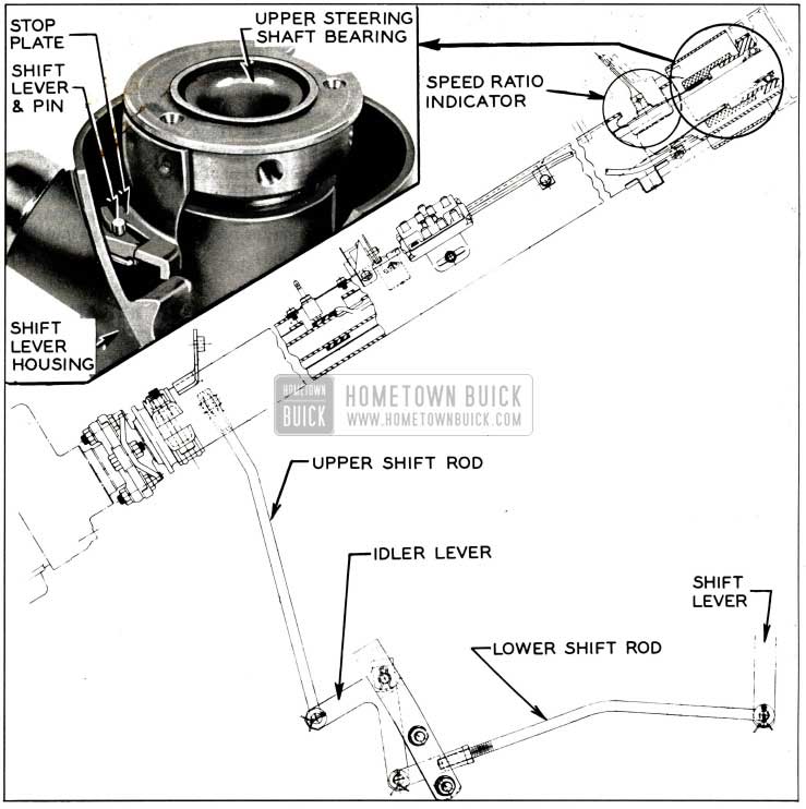
1958 Buick Shift Linkage, Lever and Stop Plate
- With manual control lever left in Drive, raise car to get at linkage adjusting clevis on lower shift rod.
- Loosen clevis lock nut. Remove clevis pin along with cotter key and spring washer.
- Make sure transmission shift lever is in Drive detent (center position of 5 possible detents).
- Move idler lever so that upper shift rod is forced upward as far as possible. Then turn clevis until clevis pin will just slip in place without moving transmission shift lever.
- Shorten lower shift rod by turning clevis 4 complete turns.
- Install clevis pin spring washer and cotter key.
- Lower car and recheck adjustment at manual control lever as described above. If movement from Drive detent to stop is still not the same as movement from Low detent to stop, readjust lower shift rod clevis slightly until movement is even.
- Park car on ramp or other grade with control lever in Parking (P) position to determine whether parking lock holds securely. Then let car roll with control lever in Neutral (N) position and listen for a clicking or ratchet noise which would indicate that parking lock pawl is contacting the parking lock ratchet wheel.
- If parking lock fails to hold or ratchet noise exists, jack car up so that a wheel may be turned to rotate propeller shaft.
- Loosen the linkage adjusting lever lock bolt on side of rear bearing retainer (fig. 5-81). With transmission in Neutral, tap rear end of lever upward until a slight ratchet noise is heard when propeller shaft is turned, then tap lever down just enough to eliminate the noise. Tighten lock bolt securely. Remove car jacks.
- With transmission warmed up and engine idling at approximately 600 RPM, slowly move control lever from Neutral (N) to Drive (D) position. The clutch should engage, as indicated by an immediate decrease in engine speed when the center of dial pointer is midway between “N” and “D” on speed ratio dial.
- Slowly move control lever .from Drive (D) position to Neutral (N) position. Clutch should disengage, as indicated by an immediate increase in engine speed, when center of speed ratio pointer is midway between “D” and “N” on speed ratio dial.
- If points of clutch engagement and disengagement are not as specified, and all preceding linkage adjustments have been correctly made, it will be necessary to remove transmission oil pan and adjust the position of the shift control valve as shown in figures 5-102 and 5-103, observing instructions in the related text.
- After adjusting Dynaflow shift control linkage, always make sure that control dial pointer lines up with letters on face of dial. If pointer does not line up, adjust pointer as described in subparagraph d below.
1958 Buick Variable Pitch Dynaflow Control Dial Pointer Adjustment
If the 1958 Buick Variable Pitch Dynaflow control dial pointer does not line up with the letters on the dial face, after checking the shift control linkage adjustment as described in subparagraph c above, adjust dial pointer as follows:
- Shift manual control lever to Neutral position.
- Remove dial by prying carefully between dial and housing until dial snaps out.
- Loosen nut holding pointer to transmission control shaft.
- Correct pointer alignment, leaving 3/16 to 1/4 inch clearance between pointer and back plate.
- Tighten nut. Snap dial back in place and recheck pointer alignment.
Leave A Comment
You must be logged in to post a comment.